EP0143743A1 - Laserbearbeitungsvorrichtung - Google Patents
Laserbearbeitungsvorrichtung Download PDFInfo
- Publication number
- EP0143743A1 EP0143743A1 EP84810512A EP84810512A EP0143743A1 EP 0143743 A1 EP0143743 A1 EP 0143743A1 EP 84810512 A EP84810512 A EP 84810512A EP 84810512 A EP84810512 A EP 84810512A EP 0143743 A1 EP0143743 A1 EP 0143743A1
- Authority
- EP
- European Patent Office
- Prior art keywords
- mode
- resonator
- diaphragm
- selective means
- laser beam
- Prior art date
- Legal status (The legal status is an assumption and is not a legal conclusion. Google has not performed a legal analysis and makes no representation as to the accuracy of the status listed.)
- Granted
Links
Images

Classifications
-
- G—PHYSICS
- G02—OPTICS
- G02B—OPTICAL ELEMENTS, SYSTEMS OR APPARATUS
- G02B27/00—Optical systems or apparatus not provided for by any of the groups G02B1/00 - G02B26/00, G02B30/00
- G02B27/09—Beam shaping, e.g. changing the cross-sectional area, not otherwise provided for
- G02B27/0927—Systems for changing the beam intensity distribution, e.g. Gaussian to top-hat
-
- B—PERFORMING OPERATIONS; TRANSPORTING
- B23—MACHINE TOOLS; METAL-WORKING NOT OTHERWISE PROVIDED FOR
- B23K—SOLDERING OR UNSOLDERING; WELDING; CLADDING OR PLATING BY SOLDERING OR WELDING; CUTTING BY APPLYING HEAT LOCALLY, e.g. FLAME CUTTING; WORKING BY LASER BEAM
- B23K26/00—Working by laser beam, e.g. welding, cutting or boring
- B23K26/02—Positioning or observing the workpiece, e.g. with respect to the point of impact; Aligning, aiming or focusing the laser beam
- B23K26/06—Shaping the laser beam, e.g. by masks or multi-focusing
- B23K26/064—Shaping the laser beam, e.g. by masks or multi-focusing by means of optical elements, e.g. lenses, mirrors or prisms
- B23K26/0643—Shaping the laser beam, e.g. by masks or multi-focusing by means of optical elements, e.g. lenses, mirrors or prisms comprising mirrors
-
- B—PERFORMING OPERATIONS; TRANSPORTING
- B23—MACHINE TOOLS; METAL-WORKING NOT OTHERWISE PROVIDED FOR
- B23K—SOLDERING OR UNSOLDERING; WELDING; CLADDING OR PLATING BY SOLDERING OR WELDING; CUTTING BY APPLYING HEAT LOCALLY, e.g. FLAME CUTTING; WORKING BY LASER BEAM
- B23K26/00—Working by laser beam, e.g. welding, cutting or boring
- B23K26/02—Positioning or observing the workpiece, e.g. with respect to the point of impact; Aligning, aiming or focusing the laser beam
- B23K26/06—Shaping the laser beam, e.g. by masks or multi-focusing
- B23K26/064—Shaping the laser beam, e.g. by masks or multi-focusing by means of optical elements, e.g. lenses, mirrors or prisms
- B23K26/0652—Shaping the laser beam, e.g. by masks or multi-focusing by means of optical elements, e.g. lenses, mirrors or prisms comprising prisms
-
- B—PERFORMING OPERATIONS; TRANSPORTING
- B23—MACHINE TOOLS; METAL-WORKING NOT OTHERWISE PROVIDED FOR
- B23K—SOLDERING OR UNSOLDERING; WELDING; CLADDING OR PLATING BY SOLDERING OR WELDING; CUTTING BY APPLYING HEAT LOCALLY, e.g. FLAME CUTTING; WORKING BY LASER BEAM
- B23K26/00—Working by laser beam, e.g. welding, cutting or boring
- B23K26/02—Positioning or observing the workpiece, e.g. with respect to the point of impact; Aligning, aiming or focusing the laser beam
- B23K26/06—Shaping the laser beam, e.g. by masks or multi-focusing
- B23K26/0665—Shaping the laser beam, e.g. by masks or multi-focusing by beam condensation on the workpiece, e.g. for focusing
-
- G—PHYSICS
- G02—OPTICS
- G02B—OPTICAL ELEMENTS, SYSTEMS OR APPARATUS
- G02B26/00—Optical devices or arrangements for the control of light using movable or deformable optical elements
- G02B26/02—Optical devices or arrangements for the control of light using movable or deformable optical elements for controlling the intensity of light
-
- G—PHYSICS
- G02—OPTICS
- G02B—OPTICAL ELEMENTS, SYSTEMS OR APPARATUS
- G02B27/00—Optical systems or apparatus not provided for by any of the groups G02B1/00 - G02B26/00, G02B30/00
- G02B27/09—Beam shaping, e.g. changing the cross-sectional area, not otherwise provided for
-
- G—PHYSICS
- G02—OPTICS
- G02B—OPTICAL ELEMENTS, SYSTEMS OR APPARATUS
- G02B27/00—Optical systems or apparatus not provided for by any of the groups G02B1/00 - G02B26/00, G02B30/00
- G02B27/09—Beam shaping, e.g. changing the cross-sectional area, not otherwise provided for
- G02B27/0938—Using specific optical elements
- G02B27/0988—Diaphragms, spatial filters, masks for removing or filtering a part of the beam
-
- G—PHYSICS
- G02—OPTICS
- G02B—OPTICAL ELEMENTS, SYSTEMS OR APPARATUS
- G02B5/00—Optical elements other than lenses
- G02B5/005—Diaphragms
-
- H—ELECTRICITY
- H01—ELECTRIC ELEMENTS
- H01S—DEVICES USING THE PROCESS OF LIGHT AMPLIFICATION BY STIMULATED EMISSION OF RADIATION [LASER] TO AMPLIFY OR GENERATE LIGHT; DEVICES USING STIMULATED EMISSION OF ELECTROMAGNETIC RADIATION IN WAVE RANGES OTHER THAN OPTICAL
- H01S3/00—Lasers, i.e. devices using stimulated emission of electromagnetic radiation in the infrared, visible or ultraviolet wave range
- H01S3/10—Controlling the intensity, frequency, phase, polarisation or direction of the emitted radiation, e.g. switching, gating, modulating or demodulating
- H01S3/106—Controlling the intensity, frequency, phase, polarisation or direction of the emitted radiation, e.g. switching, gating, modulating or demodulating by controlling devices placed within the cavity
-
- B—PERFORMING OPERATIONS; TRANSPORTING
- B23—MACHINE TOOLS; METAL-WORKING NOT OTHERWISE PROVIDED FOR
- B23K—SOLDERING OR UNSOLDERING; WELDING; CLADDING OR PLATING BY SOLDERING OR WELDING; CUTTING BY APPLYING HEAT LOCALLY, e.g. FLAME CUTTING; WORKING BY LASER BEAM
- B23K2101/00—Articles made by soldering, welding or cutting
- B23K2101/007—Marks, e.g. trade marks
-
- H—ELECTRICITY
- H01—ELECTRIC ELEMENTS
- H01S—DEVICES USING THE PROCESS OF LIGHT AMPLIFICATION BY STIMULATED EMISSION OF RADIATION [LASER] TO AMPLIFY OR GENERATE LIGHT; DEVICES USING STIMULATED EMISSION OF ELECTROMAGNETIC RADIATION IN WAVE RANGES OTHER THAN OPTICAL
- H01S2301/00—Functional characteristics
- H01S2301/20—Lasers with a special output beam profile or cross-section, e.g. non-Gaussian
-
- H—ELECTRICITY
- H01—ELECTRIC ELEMENTS
- H01S—DEVICES USING THE PROCESS OF LIGHT AMPLIFICATION BY STIMULATED EMISSION OF RADIATION [LASER] TO AMPLIFY OR GENERATE LIGHT; DEVICES USING STIMULATED EMISSION OF ELECTROMAGNETIC RADIATION IN WAVE RANGES OTHER THAN OPTICAL
- H01S3/00—Lasers, i.e. devices using stimulated emission of electromagnetic radiation in the infrared, visible or ultraviolet wave range
- H01S3/05—Construction or shape of optical resonators; Accommodation of active medium therein; Shape of active medium
- H01S3/08—Construction or shape of optical resonators or components thereof
- H01S3/08018—Mode suppression
- H01S3/0804—Transverse or lateral modes
- H01S3/08045—Single-mode emission
-
- H—ELECTRICITY
- H01—ELECTRIC ELEMENTS
- H01S—DEVICES USING THE PROCESS OF LIGHT AMPLIFICATION BY STIMULATED EMISSION OF RADIATION [LASER] TO AMPLIFY OR GENERATE LIGHT; DEVICES USING STIMULATED EMISSION OF ELECTROMAGNETIC RADIATION IN WAVE RANGES OTHER THAN OPTICAL
- H01S3/00—Lasers, i.e. devices using stimulated emission of electromagnetic radiation in the infrared, visible or ultraviolet wave range
- H01S3/05—Construction or shape of optical resonators; Accommodation of active medium therein; Shape of active medium
- H01S3/08—Construction or shape of optical resonators or components thereof
- H01S3/08018—Mode suppression
- H01S3/0804—Transverse or lateral modes
- H01S3/0805—Transverse or lateral modes by apertures, e.g. pin-holes or knife-edges
Definitions
- the invention relates to a device for processing a workpiece by means of a laser beam according to the preamble of patent claim 1.
- the problem with laser material processing is often that a beam of high intensity is required for certain work (e.g. labeling, trimming, etc.), but a beam with high power is required for other processing (e.g. soldering, etc.).
- the device according to the invention is therefore equipped with a servo-controlled adjustable mode diaphragm for influencing the transverse mode distribution.
- An externally similar adjustable mode diaphragm which is fundamentally different in its purpose and function, is used in a gas laser described in US Pat. No. 3,689,293. There it has the task of frequency tuning the gas laser, which oscillates fundamentally and exclusively in the lowest transverse mode. The problem of changing the transverse mode distribution does not arise with this laser at all.
- US Pat. No. 3,940,712 describes a special modulator for a laser generator, with which the frequency or phase of the laser oscillations can be varied.
- the modulator consists of a totally reflecting prism inserted into the laser resonator, on the base surface of which a mirror is arranged in parallel at a distance, the distance between the mirror and the base surface being able to be adjusted piezoelectrically.
- This modulator influences the effective resonator length and thus the frequency or phase position of the laser vibrations.
- it is not suitable for changing the mode distribution, in particular that of the transverse modes.
- WO 81/02953 (published PCT patent application Publ.No. WO 81/02953) describes a waveguide laser which is aligned with a deflection prism for folding the beam path.
- a further prism is arranged in parallel at a distance, the distance being variable.
- the quality of the laser oscillation can be influenced by changing this distance, but this arrangement is not suitable for mode variation.
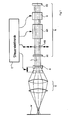
- FIG. 1 The most important components of a laser processing device according to the invention can be seen in FIG. 1. These are a laser generator G for generating a laser beam L, optics 0 for focusing the laser beam onto a workpiece W, a beam expander A and control electronics E controlling the generator G and beam expander A.
- the laser generator G consists of a resonator defined by two mirrors M 1 and M 2 , an active medium AM, a Q switch Q and a mode diaphragm MB.
- the device shown corresponds to the state of the art and therefore requires no further explanation.
- the mode diaphragm MB and the beam expander A are not permanently mounted or set, but their effect can be changed or adjusted via servo means indicated only by arrows. In this way, the beam parameters can be easily and quickly adapted to the most diverse operating requirements via control electronics.
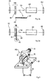
- the mode diaphragm MB consists of a fixed diaphragm part B 1 which is permanently in the beam path and a movable diaphragm part B 2 which can be swiveled into the beam path and whose axis of rotation A 2 crosses the optical axis OA of the system perpendicularly or parallel to or in the Level of the movable panel part B 2 is.
- a large beam cross section results, when the diaphragm part B 2 (FIG. 2b) is pivoted in, a correspondingly smaller one.
- FIG. 3 shows a practical embodiment of a changeable mode diaphragm MB.
- the fixed diaphragm part is designed in a conventional manner as a tube 10 with a threaded connector 11, which is screwed into an adjustment bracket, not shown.
- a bracket 20 is attached to the tube 10 and fixed with grub screws 12.
- a DC motor 30 is fastened in the bracket 20, the shaft 31 of which carries a lamella 40 which forms the movable diaphragm part B 2 .
- a stop pin 50 limits the pivoting movement of the lamella 40 in the direction away from the tube 10.
- the lamella 40 can be pivoted into the beam path in front of the tube 10 or pivoted out of it. With an appropriate choice of motor, this can be done e.g. B. done very easily using TTL signals.
- an aperture revolver wheel with different apertures
- continuously adjustable apertures iris apertures
- FIG. 5a and 5b show another possibility for the selection of different transverse modes of the laser.
- an aperture B 7 is rotated about a pivot axis A 7 lying in its plane and intersecting the optical axis OA of the system, and thus the effective beam cross section is changed.
- FIG. 5a there is, for example, a laser beam with TEMl 1 mode, in the position shown in FIG. 5b one with TEM 0.1 mode.
- the beam should be influenced quickly, continuously and if possible without large mechanical movements.
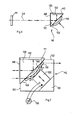
- SLM spatial light modulator element
- This modulator element ME essentially consists of a totally reflecting deflection prism 100, one side surface 101 of which is oriented perpendicularly and the other side surface 102 of which is aligned parallel to the optical axis OA of the laser resonator.
- the vertical side surface 101 is provided with an antireflection coating AR, the parallel side surface 102 carries the resonator mirror M2.
- a concave plate 110 which is transparent to the laser radiation and is made of an elastically somewhat deformable material (for example glass), is provided on the base surface 103 of the deflecting prism 100.
- This plate 110 is pressed against the base surface 103 of the prism 100 by means of a piezo-electric adjustment element 120, which is supported on a counter bearing 130, so that it rests on the base surface 103 along its edge 111.
- the piezoelectric adjustment element 120 is connected to an adjustable voltage source 150, which in practice is formed by the control electronics E. Depending on the applied voltage, the piezo-electric adjusting element 120 then presses the plate 110 more or less strongly to the deflection prism 100.
- the air gap 160 changes between the concave side of the plate 110 and the base surface 103 and thus changes the mode distribution of the laser beam.
- the modulator element ME works on the principle of frustrated total reflection, also called optical tunnel effect. If only the prism were present, the laser beam would be totally reflected at the base surface. The "transversely damped wave" excited on the base surface cannot be radiated into the optically thinner medium for electrodynamic reasons. However, if plate 110 is now approached to the base surface, the surface wave is influenced and can radiate part of its energy into the approximated plate. As a result, the incident wave is no longer totally reflected, but only to a fraction that depends on the distance of the plate. By modulating the distance between the plates, the shaft can be modulated.
- the invention does not use a flat, but rather a concave plate 100, so that the air gap varies as a function of the location.
- the reflectivity is also so great that laser emission can take place.
- This area corresponds to the free opening in a conventional mode diaphragm.
- the modulator element ME therefore corresponds to an electrically continuously adjustable diaphragm for mode selection of a laser.
- the shape of the effective "opening" of this mode selector can be varied e.g. B. by the shape of the approximate plate by the design of the mechanical transition between the piezoelectric element and the back of the plate, by the design of the prism, or by means of additional elements in the laser resonator (z. B. cylindrical lenses). It also goes without saying that the plate does not necessarily have to be in direct contact with the base surface of the prism, but can also be arranged at a distance from it with a suitable shape.
- the laser beam L can be transformed outside the resonator by means of adaptive-optical elements, preferably coupled with the beam manipulations within the resonator.
- adaptive-optical elements are motor-displaceable optical components (lenses, mirrors, gratings, prisms, holograms, diaphragms) and electrically controllable optical elements (liquid crystal cells, deformable mirrors and other elements, spatial and temporal light modulators, attenuators, etc.).
- motor-displaceable optical components laenses, mirrors, gratings, prisms, holograms, diaphragms
- electrically controllable optical elements liquid crystal cells, deformable mirrors and other elements, spatial and temporal light modulators, attenuators, etc.
- the invention described above thus provides modifiable mode-selective means in the resonator, which enable the servo-controlled adjustment of the beam parameters (mode structure, divergence, beam diameter, power) for the respective operating case via computer.
Abstract
Description
- Die Erfindung betrifft eine Vorrichtung zur Bearbeitung eines Werkstücks mittels eines Laserstrahls gemäss Oberbegriff von Patentanspruch 1.
- Bei der Lasermaterialbearbeitung stellt sich oft das Problem, dass man für gewisse Arbeiten (z.B. Beschriften, Trimmen etc.) einen Strahl hoher Intensität, für andere Bearbeitungen (z.B. Löten etc.) jedoch einen Strahl mit hoher Leistung benötigt.
- Ueblicherweise verwendet man deshalb verschiedene Laser und optische Anordnungen bzw. man rüstet eine bestehende Anlage von Hand um. Zur optimalen Anpassung der Strahlparameter (z.B. Strahldurchmesser auf dem Werkstück und Leistung) ist es allgemein notwendig, optische Komponenten sowohl im Inneren des Laserresonators (z.B. Modenblenden, Linsen) als auch ausserhalb des Resonators (z.B. Strahlaufweiter, Linsen, Blenden, Filter) zu montieren, auszuwechseln bzw. zu verstellen.
- Sollen jedoch z.B. auf ein- und demselben Werkstück verschiedene Bearbeitungen durchgeführt werden, für die unterschiedliche Strahlparameter erforderlich sind, so dauern die Umrüstzeiten in vielen Fällen zu lang. Ausserdem ist das Umrüsten von Hand umständlich und oft gefährlich (Laserstrahlung, elektrische Spannungen).
- Durch die Erfindung soll nun dieser Mangel behoben und eine Laserbearbeitungsvorrichtung der zur Rede stehenden Art dahingehend verbessert werden, dass ein ferngesteuertes, maschinelles Umrüsten für verschiedene Anwendungsfälle möglich ist. Insbesondere soll die Variation der transversalen Modenverteilung vereinfacht werden.
- Die dieser Aufgabe gerecht werdende erfindungsgemässe Vorrichtung ist in Patentanspruch 1 beschrieben. Besonders vorteilhafte und zweckmässige Ausführungsformen ergeben sich aus den abhängigen Ansprüchen.
- Die erfindungsgemässe Vorrichtung ist also mit einer servogesteuert verstellbaren Modenblende zur Beeinflussung der transversalen Modenverteilung ausgerüstet. Eine äusserlich ähnliche, in ihrer Zweckbestimmung und Funktion jedoch grundsätzlich verschiedene verstellbare Modenblende wird bei einem in US-PS 3 689 293 beschriebenen Gaslaser eingesetzt. Sie hat dort die Aufgabe der Frequenzabstimmung des grundsätzlich und ausschliesslich im niedrigsten Transversalmode schwingenden Gas-Lasers. Das Problem der Veränderung der transversalen Modenverteilung stellt sich bei diesem Laser überhaupt nicht.
- In US-PS 3 940 712 ist ein spezieller Modulator für einen Lasergenerator beschrieben, mit welchem die Frequenz bzw. Phase der Laserschwingungen variiert werden kann. Der Modulator besteht aus einem in den Laser-Resonator eingefügten totalreflektierenden Prisma, an dessen Basisfläche parallel im Abstand ein Spiegel angeordnet ist, wobei der Abstand zwischen Spiegel und Basisfläche piezoelektrisch verstellt werden kann. Dieser Modulator beeinflusst die wirksame Resonatorlänge und damit die Frequenz bzw.Phasenlage der Laser-Schwingungen. Er ist jedoch nicht dazu geeignet, die Modenverteilung, insbesondere die der transversalen Moden, zu verändern.
- In WO 81/02953 (veröffentlichte PCT-Patentanmeldung Publ.No. WO 81/02953) ist ein Wellenleiter-Laser beschrieben, der mit einem Umlenk-Prisma zur Faltung des Strahlenganges ausgerichtet ist. In einer der Katheten - Flächen des Umlenk-Prismas ist parallel im Abstand ein weiteres Prisma angeordnet, wobei der Abstand veränderbar ist. Durch die Veränderung dieses Abstandes lässt sich die Güte der Laserschwingung beeinflussen, zur Modenvariation ist diese Anordnung jedoch nicht geeignet.
- Im folgenden wird die Erfindung anhand der Zeichnung näher erläutert. Es zeigen:
- Fig. 1 eine schematische Gesamtdarstellung eines Ausführungsbeispiels einer erfindungsgemässen Laserbearbeitungsvorrichtung,
- Fig. 2a und 2b eine schematische Detailansicht in zwei verschiedenen Arbeitsstellungen,
- Fig. 3 einen Schrägriss eines konkreten Ausführungsbeispiels des Details aus Fig. 2a und 2b und
- Fig. 4 bis 7 schematische Darstellungen weiterer Detailvarianten.
- Die wesentlichsten Bestandteile einer erfindungsgemässen Laserbearbeitungsvorrichtung sind Fig. 1 zu entnehmen. Es sind dies ein Lasergenerator G zur Erzeugung eines Laserstrahls L, eine Optik 0 zur Fokussierung des Laserstrahls auf ein Werkstück W, ein Strahlenaufweiter A und eine den Generator G und den Strahlenaufweiter A steuernde Steuerelektronik E.
- Der Lasergenerator G besteht aus einem durch zwei Spiegel M1 und M2 definierten Resonator, einem aktiven Medium AM, einem Güteschalter (Q-Switch) Q und einer Modenblende MB.
- Die dargestellte Vorrichtung entspricht soweit dem Stand der Technik und bedarf daher keiner weiteren Erläuterung. Im Unterschied zu bekannten Vorrichtungen dieser Art sind jedoch bei der erfindungsgemässen Vorrichtung die Modenblende MB und der Strahlenaufweiter A nicht fest montiert bzw. eingestellt, sondern über hier nur durch Pfeile angedeutete Servomittel in ihrer Wirkung veränder- bzw. verstellbar ausgebildet. Auf diese Weise lassen sich die Strahlparameter via Steuerelektronik einfach und schnell den unterschiedlichsten Betriebserfordernissen anpassen.
- Die prinzipielle Realisation einer verstellbaren Modenblende MB geht z.B. aus den Fig. 2a und 2b hervor. Wie man erkennt, besteht die Modenblende MB aus einem feststehenden, permanent im Strahlengang befindlichen Blendenteil B1 und einem in den Strahlengang einschwenkbaren, beweglichen Blendenteil B2, dessen Drehachse A2 die optische Achse OA des Systems senkrecht kreuzt bzw. parallel zur oder in der Ebene des beweglichen Blendenteils B2 liegt. Bei ausgeschwenktem Blendenteil B2 (Fig. 2a) ergibt sich ein grosser Strahlquerschnitt, bei eingeschwenktem Blendenteil B2 (Fig. 2b) ein entsprechend kleinerer.
- Fig. 3 zeigt eine praktische Ausführungsform einer veränderbaren Modenblende MB. Der feststehende Blendenteil ist in konventioneller Weise als Rohr 10 mit Gewindestutzen 11 ausgebildet, das in einer nicht gezeigten Justierhalterung eingeschraubt ist. Am Rohr 10 ist ein Haltewinkel 20 befestigt und mit Madenschrauben 12 fixiert. Im Haltewinkel 20 ist ein Gleichstrommotor 30 befestigt, dessen Welle 31 eine Lamelle 40 trägt, welche den beweglichen Blendenteil B2 bildet. Ein Anschlagstift 50 begrenzt die Schwenkbewegung der Lamelle 40 in Richtung vom Rohr 10 weg. Durch Beaufschlagen des Elektromotors 30 mit elektrischer Spannung der einen oder der anderen Polarität kann die Lamelle 40 in den Strahlengang vor das Rohr 10 geschwenkt bzw. aus diesem heraus geschwenkt werden. Bei entsprechender Wahl des Motors kann dies z. B. sehr einfach mittels TTL-Signalen erfolgen.
- Die besonderen Vorteile einer variablen Modenblende MB gemäss Fig. 3 sind:
- - direkter Ersatz für bisher übliche fixe Blenden ohne Aenderungen an bestehenden üblichen Halterungen unter Beibehaltung der Justiermöglichkeiten,
- - exakte Positionierung ohne mechanische Anschläge, die sich durch Gebrauch abnutzen könnten,
- - Abführung der Verlustleistung von der dünnen Blenden-Lamelle auf die im Haltewinkel eingeschraubte massive Fest-Blende,
- - kompakte, einfache Konstruktion,
- - weiches Arbeiten durch Verwendung eines Gleichstrommotors, wobei die Charakteristik der Bewegung/Beschleunigung durch die Art der elektrischen Ansteuerung einfach wählbar ist.
- Wie Fig. 4 zeigt, ist es ohne weiteres auch möglich, mehrere bewegliche Blendenteile B29 B3, B4' B5 vorzuziehen und damit eine grössere Vielzahl der Blendeneinstellungen zu erreichen.
- Statt einzelner Blenden können jedoch auch ein Blendenrevolver (Rad mit verschiedenen Blenden) oder kontinuierlich verstellbare Blenden (Iris-Blenden) verwendet werden. Aufgrund der sehr kritischen Stabilität und Präzision der Lage der Blende sind solche Konstruktionen jedoch aufwendiger. Zudem ist das Problem der Kühlung bei Hochleistungslasern dann schwieriger zu lösen.
- Eine weitere Möglichkeit zur Selektion verschiedener transversaler Moden des Lasers zeigen Fig. 5a und 5b. Hier wird eine Blende B7 um eine in ihrer Ebene liegende und die optische Achse OA des Systems schneidende Schwenkachse A7 gedreht und damit der effektive Strahlquerschnitt verändert. In der Fig. 5a gezeigten Drehstellung ergibt sich z.B. ein Laserstrahl mit TEMl 1-Mode, in der Stellung gemäss Fig. 5b ein solcher mit TEM 0,1 -Mode.
- In gewissen Fällen soll die Strahlbeeinflussung schnell, kontinuierlich und wenn möglich ohne grosse mechanische Bewegungen erfolgen. Dies lässt sich durch die in Fig. 6 und 7 dargestellte Ausbildungsvariante erreichen, bei der die variable Modenblende MB im Resonator durch ein den sogenannten optischen Tunneleffekt ausnutzendes, räumliches Lichtmodulatorelement (SLM = spatial light modulator) ME ersetzt ist.
- Dieses Modulatorelement ME besteht im wesentlichen aus einem totalreflektierenden Umlenkprisma 100, dessen eine Seitenfläche 101 senkrecht und dessen andere Seitenfläche 102 parallel zur optischen Achse OA des Laserresonators ausgerichtet ist. Die senkrechte Seitenfläche 101 ist mit einem Antireflex-Belag AR versehen, die parallele Seitenfläche 102 trägt den Resonatorspiegel M2.
- An der Basisfläche 103 des Umlenkprismas 100 ist eine konkave, für die Laserstrahlung transparente Platte 110 aus einem elastisch etwas deformierbaren Material (z.B. Glas)vorgesehen. Diese Platte 110 wird mittels eines piezo-elektrischen Verstellelements 120, das sich auf einem Gegenlager 130 abstützt, gegen die Basisfläche 103 des Prismas 100 gepresst, so dass es längs seines Rands 111 auf der Basisfläche 103 aufliegt. Das piezo-elektrische Verstellelement 120 ist an eine einstellbare Spannungsquelle 150, die in der Praxis durch die Steuerelektronik E gebildet ist, angeschlossen. Je nach anliegender Spannung drückt dann das piezo-elektrische Verstellelement 120 die Platte 110 mehr oder weniger stark an das Umlenkprisma 100 an. Dabei verändert sich der Luftspalt 160 zwischen der konkaven Seite der Platte 110 und der Basisfläche 103 und verändert damit die Modenverteilung des Laserstrahls.
- Das Modulatorelement ME arbeitet nach dem Prinzip der frustrierten Totalreflexion, auch optischer Tunneleffekt genannt. Wäre nur das Prisma vorhanden, würde der Laserstrahl an dessen Basisfläche total reflektiert werden. Die dabei an der Basisfläche angeregte "quergedämpfte Welle" kann aus elektrodynamischen Gründen nicht in das optisch dünnere Medium abgestrahlt werden. Wird nun aber die Platte 110 der Basisfläche genähert, so wird die Oberflächenwelle beeinflusst und kann einen Teil ihrer Energie in die angenäherte Platte abstrahlen. Dadurch wird die einfallende Welle nicht mehr total reflektiert, sondern nur noch zu einem Bruchteil, der vom Abstand der Platte abhängt. Durch Steuerung des Plattenabstands ist somit eine Modulation der Welle möglich.
- Bei der Erfindung wird keine ebene, sondern eine konkave Platte 100 benützt, so dass der Luftspalt als Funktion des Ortes variert. Im zentralen Bereich der Prisma-Basisfläche, wo der Abstand zur Platte 100 relativ gross ist, ist auch das Reflexionsvermögen so gross, dass eine Laseremission stattfinden kann. Dieser Bereich entspricht der freien Oeffnung bei einer konventionellen Modenblende. Das Modulatorelement ME entspricht daher einer elektrisch stufenlos einstellbaren Blende zur Modenselektion eines Lasers.
- Die Form der effektiven "Oeffnung" dieses Modenselektors kann variiert werden z. B. durch die Form der angenäherten Platte durch die Gestaltung des mechanischen Uebergangs zwischen piezoelektrischem Element und der Rückseite der Platte, durch die Gestaltung des Prismas, oder mittels zusätzlicher Elemente im Laserresonator(z. B. Zylinderlinsen). Es versteht sich im übrigen auch, dass die Platte nicht unbedingt in direktem Kontakt mit der Basisfläche des Prismas sein muss, sondern bei geeigneter Formgebung auch im Abstand davon angeordnet sein kann.
- Zur weiteren Anpassung an die Art der mit der Vorrichtung durchzuführenden Bearbeitung kann der Laserstrahl L ausserhalb des Resonators mittels adaptiv-optischer Elemente transformiert werden, vorzugsweise gekoppelt mit den Strahlmanipulationen innerhalb des Resonators. Beispiele solcher adaptivoptischer Elemente sind motorisch verschiebbare optische Komponenten (Linsen, Spiegel, Gitter, Prismen, Hologramme, Blenden) und elektrisch steuerbare optische Elemente (Flüssigkristallzellen, deformierbare Spiegel und andere Elemente, räumliche und zeitliche Lichtmodulatoren, Abschwächer etc.). In Fig. 1 ist stellvertretend für alle diese Möglichkeiten nur die Vorstellbarkeit des Gauss'- schen Strahlaufweiters A angedeutet. Wesentlich für eine optimale Anpassung der Strahlparameter ist jedoch in jedem Fall, dass die entsprechenden Manipulationen innerhalb des Resonators vorgenommen werden. Eine Aenderung der optischen Komponenten ausserhalb des Resonators allein führt in der Regel nicht zu befriedigenden Ergebnissen.
- Durch die vorstehend beschriebene Erfindung werden also veränderbare moden-selektive Mittel im Resonator bereitgestellt, die die servoge-': steuerte Anpassung der Strahlparameter (Modenstruktur, Divergenz, Strahldurchmesser, Leistung) für den jeweiligen Betriebsfall via Computer ermöglichen.
Claims (9)
Applications Claiming Priority (2)
| Application Number | Priority Date | Filing Date | Title |
|---|---|---|---|
| CH584883 | 1983-10-28 | ||
| CH5848/83 | 1983-10-28 |
Publications (3)
| Publication Number | Publication Date |
|---|---|
| EP0143743A1 true EP0143743A1 (de) | 1985-06-05 |
| EP0143743B1 EP0143743B1 (de) | 1987-03-04 |
| EP0143743B2 EP0143743B2 (de) | 1991-03-13 |
Family
ID=4300314
Family Applications (1)
| Application Number | Title | Priority Date | Filing Date |
|---|---|---|---|
| EP84810512A Expired - Lifetime EP0143743B2 (de) | 1983-10-28 | 1984-10-22 | Laserbearbeitungsvorrichtung |
Country Status (4)
| Country | Link |
|---|---|
| US (1) | US4675500A (de) |
| EP (1) | EP0143743B2 (de) |
| JP (1) | JPS60111788A (de) |
| DE (1) | DE3462568D1 (de) |
Cited By (11)
| Publication number | Priority date | Publication date | Assignee | Title |
|---|---|---|---|---|
| WO1987001819A2 (en) * | 1985-09-11 | 1987-03-26 | G. Rodenstock Instrumente Gmbh | Device for generating a laser spot of controllable size |
| EP0296497A1 (de) * | 1987-06-19 | 1988-12-28 | EUROPÄISCHE WIRTSCHAFTSGEMEINSCHAFT Bâtiment Jean Monnet | Kontinuierlich variables Laserstrahl-Dämpfungsglied |
| EP0360165A2 (de) * | 1988-09-19 | 1990-03-28 | Firma Carl Zeiss | Laseranordnung mit ein- und ausschaltbarer Frequenzkonversion |
| GB2228440A (en) * | 1988-12-08 | 1990-08-29 | Andrew Victor Polijanczuk | Improvements to soldering by laser |
| FR2647042A1 (fr) * | 1989-05-18 | 1990-11-23 | Diehl Gmbh & Co | Dispositif de guidage de faisceau pour l'usinage de pieces au laser |
| EP0428734A1 (de) * | 1989-05-08 | 1991-05-29 | Fanuc Ltd. | Bearbeitungsvorrichtung mit laser |
| EP0464213A1 (de) * | 1990-01-19 | 1992-01-08 | Fanuc Ltd. | Laserschneideverfahren |
| WO2007056595A1 (en) * | 2005-11-09 | 2007-05-18 | Thomson Licensing | Optical seaming adjuster |
| EP1850165A1 (de) * | 2006-04-27 | 2007-10-31 | Ricoh Company, Ltd. | Lichtquellensystem, optischer Scanner, Bildformungsvorrichtung, Verfahren zur Lichtvolumenkontrolle, optisches Abtastverfahren und Bildformungsverfahren |
| EP1944839A2 (de) * | 2007-01-12 | 2008-07-16 | Peacock LLC | Laserresonator, insbesondere für eine Laserschweißvorrichtung |
| CN101862901A (zh) * | 2010-06-21 | 2010-10-20 | 苏州市博海激光科技有限公司 | 聚焦光点无规则偏转的激光辊类表面毛化加工方法及装置 |
Families Citing this family (34)
| Publication number | Priority date | Publication date | Assignee | Title |
|---|---|---|---|---|
| US4910739A (en) * | 1988-03-21 | 1990-03-20 | Spectra-Physics | Adjustable aperture |
| US4977575A (en) * | 1989-08-24 | 1990-12-11 | Spectra-Physics, Inc. | Adjustable aperture comprising a shape memory alloy and laser using same |
| DE3930495C2 (de) * | 1989-09-12 | 1996-11-07 | Rofin Sinar Laser Gmbh | Einrichtung zum Einstellen von Fokusdurchmesser und Fokuslage eines Laserstrahls |
| DE4018006A1 (de) * | 1990-06-05 | 1991-12-12 | Baasel Carl Lasertech | Laser mit modenblende |
| EP0599154A1 (de) * | 1992-11-20 | 1994-06-01 | Ascom Tech Ag | Modulator für einen Lichtstrahl |
| US5455709A (en) * | 1993-03-23 | 1995-10-03 | Martin Marietta Corporation | Total internal reflection spatial light modulation apparatus and method of fabrication thereof |
| JP3399590B2 (ja) * | 1993-08-04 | 2003-04-21 | 富士通株式会社 | 配線の切断装置 |
| US5444723A (en) * | 1993-08-18 | 1995-08-22 | Institut National D'optique | Optical switch and Q-switched laser |
| AUPM316293A0 (en) * | 1993-12-24 | 1994-07-28 | Electro Optic Systems Pty Limited | Improved laser cavity assembly |
| JP3159593B2 (ja) * | 1994-02-28 | 2001-04-23 | 三菱電機株式会社 | レーザ加工方法及びその装置 |
| US5656186A (en) * | 1994-04-08 | 1997-08-12 | The Regents Of The University Of Michigan | Method for controlling configuration of laser induced breakdown and ablation |
| DE19549531B4 (de) * | 1994-10-14 | 2007-12-13 | Mitsubishi Denki K.K. | Festkörperlaservorrichtung und Laserbearbeitungsvorrichtung |
| US5491319A (en) * | 1994-12-19 | 1996-02-13 | International Business Machines Corporation | Laser ablation apparatus and method |
| US5886318A (en) * | 1995-11-03 | 1999-03-23 | Vasiliev; Anatoly Valentinovich | Method for laser-assisted image formation in transparent objects |
| US5834094A (en) * | 1996-09-30 | 1998-11-10 | Surface Technologies Ltd. | Bearing having micropores and design method thereof |
| US5808780A (en) * | 1997-06-09 | 1998-09-15 | Texas Instruments Incorporated | Non-contacting micromechanical optical switch |
| US6926487B1 (en) | 1998-04-28 | 2005-08-09 | Rexam Ab | Method and apparatus for manufacturing marked articles to be included in cans |
| JP3178524B2 (ja) * | 1998-11-26 | 2001-06-18 | 住友重機械工業株式会社 | レーザマーキング方法と装置及びマーキングされた部材 |
| US6449081B1 (en) * | 1999-06-16 | 2002-09-10 | Canon Kabushiki Kaisha | Optical element and optical device having it |
| US6479787B1 (en) * | 1999-10-05 | 2002-11-12 | Rexam Ab | Laser unit and method for engraving articles to be included in cans |
| US6872913B1 (en) | 2000-01-14 | 2005-03-29 | Rexam Ab | Marking of articles to be included in cans |
| US6455806B1 (en) | 2000-01-14 | 2002-09-24 | Rexam Ab | Arrangement for shaping and marking a target |
| US6926456B1 (en) | 2000-01-20 | 2005-08-09 | Rexam Ab | Guiding device for a marking arrangement |
| US6341009B1 (en) | 2000-02-24 | 2002-01-22 | Quantronix Corporation | Laser delivery system and method for photolithographic mask repair |
| US6576871B1 (en) | 2000-04-03 | 2003-06-10 | Rexam Ab | Method and device for dust protection in a laser processing apparatus |
| DE10245617A1 (de) * | 2002-09-30 | 2004-04-08 | Eos Gmbh Electro Optical Systems | Vorrichtung und Verfahren zum schichtweisen Herstellen von dreidimensionalen Objekten |
| ATE411870T1 (de) * | 2003-07-18 | 2008-11-15 | Trumpf Laser Gmbh & Co Kg | Laserbearbeitungsmaschine mit modulator zum verändern der laserleistung |
| US7645300B2 (en) | 2004-02-02 | 2010-01-12 | Visiogen, Inc. | Injector for intraocular lens system |
| DE102004027621A1 (de) * | 2004-06-05 | 2006-01-12 | Rehau Ag + Co. | Laserstrahlmarkiervorrichtung, Laserstrahlmarkierverfahren sowie Verwendung einer Laserstrahlmarkiervorrichtung |
| US7249855B2 (en) * | 2004-12-21 | 2007-07-31 | Hewlett-Packard Development Company, L.P. | System and method of image enhancement through light intensity modulation in digital projectors |
| US20070211352A1 (en) * | 2006-03-09 | 2007-09-13 | Nikon Corporation | Aperture changing apparatus and method |
| US8598488B2 (en) * | 2011-12-23 | 2013-12-03 | Electro Scientific Industries, Inc. | Method and apparatus for adjusting radiation spot size |
| JP5964621B2 (ja) * | 2012-03-16 | 2016-08-03 | 株式会社ディスコ | レーザー加工装置 |
| JP6306659B1 (ja) * | 2016-10-19 | 2018-04-04 | ファナック株式会社 | ビーム分配器 |
Citations (7)
| Publication number | Priority date | Publication date | Assignee | Title |
|---|---|---|---|---|
| US3426293A (en) * | 1964-10-07 | 1969-02-04 | American Optical Corp | Diaphragm tuning of gas laser |
| US3689293A (en) | 1970-07-08 | 1972-09-05 | Corning Glass Works | Mica glass-ceramics |
| US3689159A (en) * | 1970-06-11 | 1972-09-05 | Mitsubishi Electric Corp | Laser processing apparatus |
| US3940712A (en) | 1974-04-11 | 1976-02-24 | White Matthew B | Modulation techniques for lasers |
| FR2377662A1 (fr) * | 1977-01-18 | 1978-08-11 | Leitz Ernst Gmbh | Regulateur de flux lumineux |
| US4283115A (en) * | 1978-06-28 | 1981-08-11 | Richard Wolf Gmbh | Beam splitters for endoscopes comprising a dual observation system |
| WO1981002953A1 (fr) | 1980-04-05 | 1981-10-15 | Eltro Gmbh | Laser a guide d'onde avec element de frustration |
Family Cites Families (11)
| Publication number | Priority date | Publication date | Assignee | Title |
|---|---|---|---|---|
| DE674294C (de) * | 1933-02-17 | 1939-04-12 | Tobis Tonbild Syndikat Akt Ges | Verfahren zur Umwandlung elektrischer Stromschwankungen in Lichtschwankungen |
| US3292102A (en) * | 1962-12-14 | 1966-12-13 | Francis T Byrne | Pulsed optical beam generator |
| US3500240A (en) * | 1964-11-30 | 1970-03-10 | Us Navy | Simple traveling wave laser using total - internal - reflection resonator |
| US3514183A (en) * | 1967-11-06 | 1970-05-26 | Ibm | Light deflector system |
| US3699474A (en) * | 1971-11-20 | 1972-10-17 | Atomic Energy Commission | Multiple beam laser system |
| BE792829A (fr) * | 1971-12-17 | 1973-03-30 | Siemens Ag | Dispositif pour devier, de facon controlee, des rayonnements optiques |
| US4032861A (en) * | 1973-11-15 | 1977-06-28 | Union Carbide Corporation | Laser device for altering surfaces in accordance with given patterns |
| JPS5368499A (en) * | 1976-11-30 | 1978-06-17 | Komatsu Ltd | Method of shaping laser beam used for machining |
| US4323317A (en) * | 1980-05-07 | 1982-04-06 | Shibuya Kogyo Company, Ltd. | Pattern controlling device for laser marker |
| US4430548A (en) * | 1982-04-26 | 1984-02-07 | Macken John A | Laser apparatus and process for cutting paper |
| US4494235A (en) * | 1983-09-27 | 1985-01-15 | Gte Government Systems Corporation | Multiple wavelength laser |
-
1984
- 1984-10-22 EP EP84810512A patent/EP0143743B2/de not_active Expired - Lifetime
- 1984-10-22 DE DE8484810512T patent/DE3462568D1/de not_active Expired
- 1984-10-24 JP JP59222317A patent/JPS60111788A/ja active Pending
- 1984-10-29 US US06/665,998 patent/US4675500A/en not_active Expired - Fee Related
Patent Citations (7)
| Publication number | Priority date | Publication date | Assignee | Title |
|---|---|---|---|---|
| US3426293A (en) * | 1964-10-07 | 1969-02-04 | American Optical Corp | Diaphragm tuning of gas laser |
| US3689159A (en) * | 1970-06-11 | 1972-09-05 | Mitsubishi Electric Corp | Laser processing apparatus |
| US3689293A (en) | 1970-07-08 | 1972-09-05 | Corning Glass Works | Mica glass-ceramics |
| US3940712A (en) | 1974-04-11 | 1976-02-24 | White Matthew B | Modulation techniques for lasers |
| FR2377662A1 (fr) * | 1977-01-18 | 1978-08-11 | Leitz Ernst Gmbh | Regulateur de flux lumineux |
| US4283115A (en) * | 1978-06-28 | 1981-08-11 | Richard Wolf Gmbh | Beam splitters for endoscopes comprising a dual observation system |
| WO1981002953A1 (fr) | 1980-04-05 | 1981-10-15 | Eltro Gmbh | Laser a guide d'onde avec element de frustration |
Cited By (19)
| Publication number | Priority date | Publication date | Assignee | Title |
|---|---|---|---|---|
| WO1987001819A2 (en) * | 1985-09-11 | 1987-03-26 | G. Rodenstock Instrumente Gmbh | Device for generating a laser spot of controllable size |
| WO1987001819A3 (fr) * | 1985-09-11 | 1987-04-23 | Rodenstock Instr | Dispositif generateur d'un spot de rayon laser de grandeur reglable |
| US4887019A (en) * | 1985-09-11 | 1989-12-12 | G. Rodenstock Instruments Gmbh | Device for the generation of a laser beam spot of adjustable size |
| EP0296497A1 (de) * | 1987-06-19 | 1988-12-28 | EUROPÄISCHE WIRTSCHAFTSGEMEINSCHAFT Bâtiment Jean Monnet | Kontinuierlich variables Laserstrahl-Dämpfungsglied |
| EP0360165A3 (de) * | 1988-09-19 | 1991-09-25 | Firma Carl Zeiss | Laseranordnung mit ein- und ausschaltbarer Frequenzkonversion |
| EP0360165A2 (de) * | 1988-09-19 | 1990-03-28 | Firma Carl Zeiss | Laseranordnung mit ein- und ausschaltbarer Frequenzkonversion |
| GB2228440A (en) * | 1988-12-08 | 1990-08-29 | Andrew Victor Polijanczuk | Improvements to soldering by laser |
| EP0428734A4 (de) * | 1989-05-08 | 1992-02-24 | ||
| EP0428734A1 (de) * | 1989-05-08 | 1991-05-29 | Fanuc Ltd. | Bearbeitungsvorrichtung mit laser |
| FR2647042A1 (fr) * | 1989-05-18 | 1990-11-23 | Diehl Gmbh & Co | Dispositif de guidage de faisceau pour l'usinage de pieces au laser |
| US5237150A (en) * | 1990-01-19 | 1993-08-17 | Fanuc Ltd. | Method of cutting workpiece with laser beam |
| EP0464213A1 (de) * | 1990-01-19 | 1992-01-08 | Fanuc Ltd. | Laserschneideverfahren |
| EP0464213A4 (en) * | 1990-01-19 | 1993-09-29 | Fanuc Ltd. | Method of laser cutting work |
| WO2007056595A1 (en) * | 2005-11-09 | 2007-05-18 | Thomson Licensing | Optical seaming adjuster |
| EP1850165A1 (de) * | 2006-04-27 | 2007-10-31 | Ricoh Company, Ltd. | Lichtquellensystem, optischer Scanner, Bildformungsvorrichtung, Verfahren zur Lichtvolumenkontrolle, optisches Abtastverfahren und Bildformungsverfahren |
| US8085457B2 (en) | 2006-04-27 | 2011-12-27 | Ricoh Company, Ltd. | Light source system, optical scanner, image forming apparatus, and light-amount control method |
| EP1944839A2 (de) * | 2007-01-12 | 2008-07-16 | Peacock LLC | Laserresonator, insbesondere für eine Laserschweißvorrichtung |
| EP1944839A3 (de) * | 2007-01-12 | 2010-03-17 | Peacock LLC | Laserresonator, insbesondere für eine Laserschweißvorrichtung |
| CN101862901A (zh) * | 2010-06-21 | 2010-10-20 | 苏州市博海激光科技有限公司 | 聚焦光点无规则偏转的激光辊类表面毛化加工方法及装置 |
Also Published As
| Publication number | Publication date |
|---|---|
| US4675500A (en) | 1987-06-23 |
| DE3462568D1 (en) | 1987-04-09 |
| EP0143743B1 (de) | 1987-03-04 |
| EP0143743B2 (de) | 1991-03-13 |
| JPS60111788A (ja) | 1985-06-18 |
Similar Documents
| Publication | Publication Date | Title |
|---|---|---|
| EP0143743B1 (de) | Laserbearbeitungsvorrichtung | |
| EP1066546B1 (de) | Verfahren und vorrichtung zur resonanzverstärkung, insbesondere zur abstimmbaren frequenzkonversion von laserstrahlung | |
| DE19955599B4 (de) | Laser mit Wellenlängenumwandlung und Bearbeitungsvorrichtung mit einem solchen Laser | |
| EP2363928B1 (de) | Laserdiodenaufbau mit reduziertem Rauschen | |
| WO1990015460A1 (de) | Frequenzverdoppelter laser | |
| DE2403501B2 (de) | Verfahren zur Regelung der Phasenanpassung einer kohärenten Sekundärstrahlung in einem nichtlinearen Kristall | |
| EP0167843B1 (de) | Anordnung zur externen Modulation von CO2-Laser-Strahlung hoher Leistung | |
| DE69921710T2 (de) | Laserquelle mit kontinuierlich abstimmbarer Wellenlänge | |
| DE60004237T2 (de) | LASER-Generatorsystem | |
| DE4335585A1 (de) | Laservorrichtung | |
| DE102019131827B4 (de) | Frequenzkonversionsanordnung zur Optimierung von Eigenschaften einer Harmonischen eines Lasers | |
| AT1859U1 (de) | Kurzpuls-laservorrichtung | |
| WO1999054782A1 (de) | Verfahren und vorrichtung zur frequenzkonversion, insbesondere zur frequenzverdopplung von festfrequenzlasern | |
| DE19946176A1 (de) | Diodengepumpter Laser mit interner Frequenzverdopplung | |
| EP0599154A1 (de) | Modulator für einen Lichtstrahl | |
| EP1116064B1 (de) | Verfahren und vorrichtung zur formung des intensitätsprofils eines laserstrahls | |
| EP4263118A1 (de) | Vorrichtung zur strahlbeeinflussung eines laserstrahls | |
| CH692638A5 (de) | Vorrichtung zum unterbrechungsfreien Auslenken eines Lichtstrahls. | |
| EP0360165B1 (de) | Laseranordnung mit ein- und ausschaltbarer Frequenzkonversion | |
| DE102018201490B3 (de) | XY-Ablenkeinheit für UV-Laserlicht sowie deren Verwendung | |
| DE4212779A1 (de) | Laser und Steuer- und Regelverfahren dafür | |
| DE10058990C2 (de) | Vorrichtung zur Bestrahlung eines Objektes für eine Aufzeichnung eines visuellen Produktes | |
| EP1485738A1 (de) | Verfahren und vorrichtung zum spleissen von lichtwellenleitern | |
| DE69531147T2 (de) | Optische Ablenkvorrichtung | |
| DD248229A1 (de) | Anordnung zur erzeugung mehrerer arbeitsstrahlenbuendel eines co tuef 2-hochleistungslasers bei gleichzeitiger externer modulation der strahlung |
Legal Events
| Date | Code | Title | Description |
|---|---|---|---|
| PUAI | Public reference made under article 153(3) epc to a published international application that has entered the european phase |
Free format text: ORIGINAL CODE: 0009012 |
|
| 17P | Request for examination filed |
Effective date: 19841024 |
|
| AK | Designated contracting states |
Designated state(s): CH DE FR GB IT LI |
|
| 17Q | First examination report despatched |
Effective date: 19860509 |
|
| GRAA | (expected) grant |
Free format text: ORIGINAL CODE: 0009210 |
|
| AK | Designated contracting states |
Kind code of ref document: B1 Designated state(s): CH DE FR GB IT LI |
|
| REF | Corresponds to: |
Ref document number: 3462568 Country of ref document: DE Date of ref document: 19870409 |
|
| RAP2 | Party data changed (patent owner data changed or rights of a patent transferred) |
Owner name: CIBA-GEIGY AG |
|
| ET | Fr: translation filed | ||
| REG | Reference to a national code |
Ref country code: CH Ref legal event code: PUE Owner name: CIBA-GEIGY AG |
|
| ITF | It: translation for a ep patent filed |
Owner name: SOCIETA' ITALIANA BREVETTI S.P.A. |
|
| PLBI | Opposition filed |
Free format text: ORIGINAL CODE: 0009260 |
|
| PLBI | Opposition filed |
Free format text: ORIGINAL CODE: 0009260 |
|
| 26 | Opposition filed |
Opponent name: SIEMENS AKTIENGESELLSCHAFT, BERLIN UND MUENCHEN Effective date: 19871126 |
|
| 26 | Opposition filed |
Opponent name: CARL BAASEL LASERTECHNIK GMBH Effective date: 19871130 |
|
| REG | Reference to a national code |
Ref country code: CH Ref legal event code: PUE Owner name: HAAS LASER SYSTEMS AG |
|
| ITPR | It: changes in ownership of a european patent |
Owner name: CESSIONE;HAAS LASER SYSTEMS AG |
|
| ITF | It: translation for a ep patent filed |
Owner name: SOCIETA' ITALIANA BREVETTI S.P.A. |
|
| REG | Reference to a national code |
Ref country code: GB Ref legal event code: 732 |
|
| REG | Reference to a national code |
Ref country code: FR Ref legal event code: TP |
|
| PUAH | Patent maintained in amended form |
Free format text: ORIGINAL CODE: 0009272 |
|
| STAA | Information on the status of an ep patent application or granted ep patent |
Free format text: STATUS: PATENT MAINTAINED AS AMENDED |
|
| 27A | Patent maintained in amended form |
Effective date: 19910313 |
|
| AK | Designated contracting states |
Kind code of ref document: B2 Designated state(s): CH DE FR GB IT LI |
|
| ET3 | Fr: translation filed ** decision concerning opposition | ||
| REG | Reference to a national code |
Ref country code: CH Ref legal event code: AEN |
|
| ITTA | It: last paid annual fee | ||
| PGFP | Annual fee paid to national office [announced via postgrant information from national office to epo] |
Ref country code: GB Payment date: 19921009 Year of fee payment: 9 |
|
| PGFP | Annual fee paid to national office [announced via postgrant information from national office to epo] |
Ref country code: FR Payment date: 19921015 Year of fee payment: 9 |
|
| PGFP | Annual fee paid to national office [announced via postgrant information from national office to epo] |
Ref country code: DE Payment date: 19921030 Year of fee payment: 9 |
|
| PGFP | Annual fee paid to national office [announced via postgrant information from national office to epo] |
Ref country code: CH Payment date: 19921118 Year of fee payment: 9 |
|
| PG25 | Lapsed in a contracting state [announced via postgrant information from national office to epo] |
Ref country code: GB Effective date: 19931022 |
|
| PG25 | Lapsed in a contracting state [announced via postgrant information from national office to epo] |
Ref country code: LI Effective date: 19931031 Ref country code: CH Effective date: 19931031 |
|
| GBPC | Gb: european patent ceased through non-payment of renewal fee |
Effective date: 19931022 |
|
| PG25 | Lapsed in a contracting state [announced via postgrant information from national office to epo] |
Ref country code: FR Effective date: 19940630 |
|
| REG | Reference to a national code |
Ref country code: CH Ref legal event code: PL |
|
| PG25 | Lapsed in a contracting state [announced via postgrant information from national office to epo] |
Ref country code: DE Effective date: 19940701 |
|
| REG | Reference to a national code |
Ref country code: FR Ref legal event code: ST |