EP0143414A2 - Pelletizing machine - Google Patents
Pelletizing machine Download PDFInfo
- Publication number
- EP0143414A2 EP0143414A2 EP84113946A EP84113946A EP0143414A2 EP 0143414 A2 EP0143414 A2 EP 0143414A2 EP 84113946 A EP84113946 A EP 84113946A EP 84113946 A EP84113946 A EP 84113946A EP 0143414 A2 EP0143414 A2 EP 0143414A2
- Authority
- EP
- European Patent Office
- Prior art keywords
- die
- teeth
- holes
- press
- pelletizing machine
- Prior art date
- Legal status (The legal status is an assumption and is not a legal conclusion. Google has not performed a legal analysis and makes no representation as to the accuracy of the status listed.)
- Granted
Links
Images
Classifications
-
- B—PERFORMING OPERATIONS; TRANSPORTING
- B30—PRESSES
- B30B—PRESSES IN GENERAL
- B30B11/00—Presses specially adapted for forming shaped articles from material in particulate or plastic state, e.g. briquetting presses, tabletting presses
- B30B11/22—Extrusion presses; Dies therefor
- B30B11/221—Extrusion presses; Dies therefor extrusion dies
-
- B—PERFORMING OPERATIONS; TRANSPORTING
- B30—PRESSES
- B30B—PRESSES IN GENERAL
- B30B11/00—Presses specially adapted for forming shaped articles from material in particulate or plastic state, e.g. briquetting presses, tabletting presses
- B30B11/22—Extrusion presses; Dies therefor
- B30B11/228—Extrusion presses; Dies therefor using pressing means, e.g. rollers moving over a perforated die plate
-
- B—PERFORMING OPERATIONS; TRANSPORTING
- B30—PRESSES
- B30B—PRESSES IN GENERAL
- B30B15/00—Details of, or accessories for, presses; Auxiliary measures in connection with pressing
- B30B15/34—Heating or cooling presses or parts thereof
Definitions
- the invention relates to a pelletizing machine in which press rolls roll on a flat, perforated die.
- Pelleting machines are used to compress and extrude various types of material under the pressure of rolls, the strands being broken or cut into pellets.
- the material is partially compacted before it is pressed into the through holes and in many cases also involves crushing and mixing the components. Crushing is particularly necessary for waste that e.g. B. contain paper, textiles, plastics, straw and other parts of plants or consist of such.
- the press rollers have already been provided with blind holes or with transverse grooves, it could happen with material with a coarse structure or with great moisture that the material was not drawn into the press nip between the press roller and die or the press rollers, which are usually freely rotatably mounted on the pan head, were compacted Material layer slid away.
- the invention has for its object to form press rolls and die so that the drawing of the material into the press nip and the crushing between press rolls and die and the passage of the material through the die are improved.
- the surfaces of the press rolls and die are provided with teeth.
- the teeth on the press rollers are designed so that they grip the supplied material and preferably between the teeth of the die and in any case in press the through holes between the teeth of the die.
- the teeth also prevent the formation of a densified layer of material on the die above its through holes. Since the die and press rollers engage the teeth at least through the material enclosed between them, the press rollers are inevitably rotated when the pan head is driven with a fixed die or the die is rotated with a fixed pan head.
- the teeth are pins in at least part of the surface, but the teeth of the press rollers press on the upper side of the die in such a way that they get as far as possible through the entry openings of the through holes.
- the through holes start from the essentially horizontal upper side of the die and run perpendicularly through it.
- the entire annular top of the die is provided with through holes between the teeth, the shape and size of which depends on the material to be machined.
- a vertical axis leads through the center of the die to the pan head.
- tapered press rollers are used, which are freely rotatable. They are mounted on inclined axes in the pan head, which is driven by a vertical shaft.
- the die and press rollers are provided with a toothing as in the case of angular drives or bevel gears, the teeth of the press rollers pressing the material between the teeth of the die and into the through holes arranged there, and at the same time tearing and tearing fibrous or flat material when pressed between the teeth rub the tooth flanks and on the base of the matrix.
- the teeth do not need to run the entire length of the line of contact between the press roller and the die. Smooth surfaces of the roll and the die can also lie between them or next to them.
- the die in particular, is subject to high wear, it is provided that the die be made in two parts and that the upper part, which is provided with the teeth and the entry openings of the through holes, be easily connected to the lower part.
- This also makes it possible to provide the lower part with special heating and / or cooling devices in order to influence the temperature of the material and to line the through holes in the lower part with ceramic bushings or bushings made of a special material to prevent the pellet strands from sliding in the Improve holes especially with aggressive media.
- a drive for a vertical shaft is accommodated in a gear housing 1. These parts are not shown.
- the vertical shaft rotates the pan head 2, on which 3 conical press rollers 4 are arranged on inclined axes, which are pressed by the pan head 2 against the flat die 5, which is firmly supported on the gear housing 1.
- a pressure device 8 for the pan head 2 sits on the vertical shaft 7.
- the press rollers 4 When the Köllerköpfs 2 rotate, the press rollers 4, whose teeth also grip material with a coarse structure, roll on the die 5.
- the space in which the press rollers 4 work is surrounded by a funnel 6 in which the material to be processed is poured in from above.
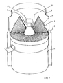
- two press rolls 4 In the pelletizing machine shown, two press rolls 4 are shown. However, three or four press rolls can also be used.
- a pelletizing machine of the type shown with four press rolls can be designed for a large material throughput and can be used for pelletizing straw, for example.
- both the die and the press rollers are provided with toothings which engage in one another, as shown in FIG. 2.
- the die 5 is composed of an upper part 51 and a lower part 52, which are secured against one another by pins 53 or in a similar manner.
- the teeth 41 on the press roller 4 engage between the teeth 54 on the upper part 51.
- the inlet openings of the through holes 56, 57 are arranged between the teeth 54.
- the through holes 57 are surrounded by ceramic bushings 58 in the region of the lower part 52.
- the lower part 52 also contains channels 59 through which a heating or cooling medium can circulate.
- the material falling on the press roller 4 or the die 5 is taken along by the teeth and compressed between teeth 41, 54. It is stretched and broken and rubbed between the tooth flanks, which destroys coarse structures.
- the reduction in the free space between two flanks of the teeth 54 by the penetration of a tooth 41 creates a high pressure in the material, which is thereby pressed into the inlet opening 55 and further into the through hole 56, 57, where the pellet is formed and as a result of the friction is further solidified on the perforated wall.
- the pressure applied during processing and the friction of the material on the surfaces of the die can lead to a strong increase. cause warming. It can therefore be expedient to protect the die 5 from overheating by means of a coolant in the channels 59.
- the introduction of a heating medium into the channels 59 can be expedient in order to remove material that is in the passages 56, 57 when the device is switched off. solidifies or becomes very hard to soften before starting the machine again.
- Ceramic bushings 58 are advantageous if the material to be machined contains aggressive constituents which attack the die, which is usually made of steel, and would produce a very rough surface of the through holes 57 at least after some time.
- the channels 59 and the bushes 58 can be dispensed with, and the teeth and the size of the passages 56, 57 have to be adapted to the respective use.
- the teeth prevent the material from jamming in front of the press rolls and improve the size reduction of the material.
- the teeth 61 of the press roller 4 are widened to approximately twice the pitch.
- a wide surface 63 corresponding to the tip circle of the teeth 61 can roll over a plurality of through holes 56 or over holes with a very large diameter and press the material into them.
- the teeth 62 of the die 5 can have a width or pitch as in FIG. 2.
- a large number of entry openings for the through holes into which the pre-comminuted and, if appropriate, previously ground and mixed material is pressed through the peripheral surface parts 63 can still be accommodated in the flat top side 64 of the die 5.
- the design of the teeth and the holes is to be selected according to the material being treated, although conical press rolls according to FIG. 1 are also preferred for designs according to this example.
- conical pressure rollers with a toothing of rollers and die as in FIG. 2 were used.
- the outside diameter of the die was approx. 760 mm, the height of the teeth approx. 10 mm.
- the die was tempered to prevent the material from melting and overheating.
- dies with diameters of approximately 300 to 1600 mm with correspondingly large press rolls can be used, teeth with a particularly large height being usable.
Abstract
Description
Die Erfindung bezieht sich auf eine Pelletiermaschine, bei der sich Pressrollen auf einer ebenen, gelochten Matrize abwälzen.The invention relates to a pelletizing machine in which press rolls roll on a flat, perforated die.
Pelletiermaschinen werden benutzt, um Material verschiedener Art unter dem Druck von Rollen zu verdichten und strangförmig auszupressen, wobei die Stränge zu Pellets zerbrechen oder zerschnitten werden. Die Verdichtung des Materials erfolgt teilweise schon vor dem Einpressen in die Durchgangslöcher und ist in vielen Fällen auch mit einem Zerkleinern und Mischen der Bestandteile verbunden. Eine Zerkleinerung ist insbesondere bei Abfällen notwendig, die z. B. Papier, Textilien, Kunststoffe, Stroh und anderen Pflanzenteile enthalten oder aus solchen bestehen. Obwohl die Pressrollen schon mit Sacklöchern oder mit Querrillen versehen wurden, konnte es bei Material von grober Struktur oder bei großer Feuchtigkeit geschehen, daß das Material nicht in den Pressenspalt zwischen Pressrolle und Matrize eingezogen wurde oder die üblicherweise frei drehbar am Kollerkopf gelagerten Pressrollen über eine verdichtete Materialschicht hinwegglitten. Großflächige oder langfaserige Bestandteile erfordern außerdem eine verhältnismäßig lange Bearbeitungszeit, ehe sie unter dem Druck der Pressrollen in die Durchgangslöcher eingedrückt werden können. Auch kann sich die durch den Pressendruck entstehende Erwärmung nachteilig auf den Pelletiervorgang bzw. auf das zu bearbeitende Material auswirken.Pelleting machines are used to compress and extrude various types of material under the pressure of rolls, the strands being broken or cut into pellets. The material is partially compacted before it is pressed into the through holes and in many cases also involves crushing and mixing the components. Crushing is particularly necessary for waste that e.g. B. contain paper, textiles, plastics, straw and other parts of plants or consist of such. Although the press rollers have already been provided with blind holes or with transverse grooves, it could happen with material with a coarse structure or with great moisture that the material was not drawn into the press nip between the press roller and die or the press rollers, which are usually freely rotatably mounted on the pan head, were compacted Material layer slid away. Large-area or long-fiber components also require a relatively long processing time before they can be pressed into the through holes under the pressure of the press rollers. The heating resulting from the press pressure can also have a disadvantageous effect on the pelleting process or on the material to be processed.
Der Erfindung liegt die Aufgabe zugrunde, Pressrollen und Matrize so auszubilden, daß das Einziehen des Materials in den Preßspalt und die Zerkleinerung zwischen Pressrollen und Matrize sowie auch der Durchgang des Materials durch die Matrize verbessert werden.The invention has for its object to form press rolls and die so that the drawing of the material into the press nip and the crushing between press rolls and die and the passage of the material through the die are improved.
Zur Lösung dieser Aufgabe sind die Oberflächen von Pressrollen und Matrize mit Zähnen versehen. Die Zähne an den Pressrollen sind so ausgebildet, daß sie das zugeführte Material ergreifen und vorzugsweise zwischen die Zähne der Matrize und in jedem Fall in die Durchgangslöcher zwischen den Zähnen der Matrize drücken. Hierdurch wird das vor dem Pressenspalt liegende Material mit Sicherheit erfaßt und zwischen Pressrolle und Matrize eingezogen. Die Zähne verhindern außerdem die Entstehung einer verdichteten Materialschicht auf der Matrize über deren Durchgangslöchern. Da Matrize und Pressrollen mit den Zähnen wenigstens durch das zwischen ihnen eingeschlossene Material in Eingriff stehen, werden die Pressrollen zwangsläufig gedreht, wenn bei fester Matrize der Kollerkopf angetrieben oder bei festem Kollerkopf die Matrize gedreht wird.To accomplish this task, the surfaces of the press rolls and die are provided with teeth. The teeth on the press rollers are designed so that they grip the supplied material and preferably between the teeth of the die and in any case in press the through holes between the teeth of the die. As a result, the material lying in front of the press nip is detected with certainty and drawn in between the press roll and the die. The teeth also prevent the formation of a densified layer of material on the die above its through holes. Since the die and press rollers engage the teeth at least through the material enclosed between them, the press rollers are inevitably rotated when the pan head is driven with a fixed die or the die is rotated with a fixed pan head.
Im einfachsten Fall sind die Zähne Stifte in wenigstens einem Teil der Oberfläche, wobei jedoch die Zähne der Presswalzen so auf die Oberseite der Matrize drücken, daß sie möglichst über die Eintrittsöffnungen der Durchgangslöcher gelangen. Die Durchgangslöcher gehen von der im wesentlichen horizontalen Oberseite der Matrize aus und verlaufen senkrecht durch sie hindurch. Die gesamte ringförmige Oberseite der Matrize ist zwischen den Zähnen mit Durchgangslöchern versehen, deren Form und Größe von dem zu bearbeitenden Material abhängt. Durch die Mitte der Matrize führt eine vertikale Achse zum Kollerkopf.In the simplest case, the teeth are pins in at least part of the surface, but the teeth of the press rollers press on the upper side of the die in such a way that they get as far as possible through the entry openings of the through holes. The through holes start from the essentially horizontal upper side of the die and run perpendicularly through it. The entire annular top of the die is provided with through holes between the teeth, the shape and size of which depends on the material to be machined. A vertical axis leads through the center of the die to the pan head.
In einer bevorzugten Ausführung werden kegelförmige Pressrollen verwendet, die frei drehbar.an geneigten Achsen im Kollerkopf gelagert sind, der über eine Königswelle angetrieben wird. In dieser Ausführung sind Matrize und Pressrollen mit einer Verzahnung wie bei Winkeltrieben oder Kegelrädern versehen, wobei die Zähne der Pressrollen das Material zwischen die Zähne der Matrize und in die dort angeordneten Durchgangslöcher eindrücken und zugleich faseriges oder flächiges Material beim Eindrücken zwischen die Zähne zerreißen und an den Zahnflanken sowie auf der Grundfläche der Matrize zerreiben. Die Zähne brauchen nicht über die ganze Länge der Berührungslinie zwischen Pressrolle und Matrize laufen. Zwischen ihnen oder neben ihnen können auch glatte Flächen der Rolle und der Matrize liegen.In a preferred embodiment, tapered press rollers are used, which are freely rotatable. They are mounted on inclined axes in the pan head, which is driven by a vertical shaft. In this version, the die and press rollers are provided with a toothing as in the case of angular drives or bevel gears, the teeth of the press rollers pressing the material between the teeth of the die and into the through holes arranged there, and at the same time tearing and tearing fibrous or flat material when pressed between the teeth rub the tooth flanks and on the base of the matrix. The teeth do not need to run the entire length of the line of contact between the press roller and the die. Smooth surfaces of the roll and the die can also lie between them or next to them.
Da insbesondere die Matrize einer großen Verschleißbeanspruchung unterliegt, ist vorgesehen, die Matrize zweiteilig auszuführen und das mit den Zähnen und den Eintrittsöffnungen der Durchgangslöcher versehene Oberteil leicht auswechselbar mit dem Unterteil zu verbinden. Dies schafft außerdem die Möglichkeit, das Unterteil mit besonderen Einrichtungen zum Heizen und/oder Kühlen zu versehen, um die Temperatur des Materials zu beeinflussen und die Durchgangslöcher im Unterteil mit keramischen Buchsen oder Buchsen aus einem besonderen Material auszukleiden, um das Gleiten der Pelletstränge in den Löchern insbesondere bei aggressiven Medien zu verbessern.Since the die, in particular, is subject to high wear, it is provided that the die be made in two parts and that the upper part, which is provided with the teeth and the entry openings of the through holes, be easily connected to the lower part. This also makes it possible to provide the lower part with special heating and / or cooling devices in order to influence the temperature of the material and to line the through holes in the lower part with ceramic bushings or bushings made of a special material to prevent the pellet strands from sliding in the Improve holes especially with aggressive media.
Auf den beigefügten Zeichnungen sind bevorzugte Ausführungsbeispiele vereinfacht dargestellt.
- Es zeigen
Figur 1 eine perspektivische Ansicht auf eine Pelletiermaschine, wobei der Einfülltrichter z.T. weggeschnitten ist, Figur 2 einen Schnitt durch einen Ausschnitt von der Matrize und einer mit ihr zusammenwirkenden Pressrolle mit einer Verzahnung gemäß Fig.1,Figur 3 einen Schnitt wie inFigur 2, jedoch mit verbreiterten Zähnen.
- FIG. 1 shows a perspective view of a pelletizing machine, the feed hopper being cut away in part,
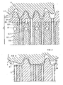
- FIG. 2 shows a section through a section of the die and a press roller interacting with it and having teeth according to FIG. 1,
- 3 shows a section as in Figure 2, but with widened teeth.
Bei der dargestellten Pelletiermaschine ist in einem Getriebegehäuse 1 ein Antrieb für eine Königswelle untergebracht. Diese Teile sind nicht gezeigt. Die Königswelle dreht den Kollerkopf 2, an dem auf geneigten Achsen 3 kegelförmige Pressrollen 4 angeordnet sind, die durch den Kollerkopf 2 gegen die ebene Matrize 5 gedrückt werden, die fest auf dem Getriebegehäuse 1 abgestützt ist. Auf der Königswelle 7 sitzt eine Andrückeinrichtung 8 für den Kollerkopf 2.In the pelletizing machine shown, a drive for a vertical shaft is accommodated in a
Bei der Drehung des Köllerköpfes 2 wälzen sich die Pressrollen 4, deren Zähne auch Material von grober Struktur erfassen, auf der Matrize 5 ab. Der Raum, in dem die Pressrollen 4 arbeiten, ist von einem Trichter 6 umgeben, in dem das aufzubereitende Material von oben eingeschüttet wird. Bei der dargestellten Pelletiermaschine sind zwei Pressrollen 4 gezeigt. Es können aber auch drei oder vier Pressrollen verwendet werden. Eine Pelletiermaschine der dargestellten Art mit vier Pressrollen kann für einen großen Materialdurchsatz ausgebildet sein und für die Pelletierung von beispielsweise Stroh verwendet werden.When the Köllerköpfs 2 rotate, the
Erfindungsgemäß sind bei diesem Beispiel sowohl die Matrize als auch die Pressrollen mit Verzahnungen versehen, die ineinander eingreifen, wie in Figur 2 gezeigt ist.According to the invention, in this example both the die and the press rollers are provided with toothings which engage in one another, as shown in FIG. 2.
Die Matrize 5 ist aus einem Oberteil 51 und einem Unterteil 52 zusammengesetzt, die durch Stifte 53 oder in ähnlicher Weise gegeneinander gesichert sind. Die Zähne 41 an der Pressrolle 4 greifen zwischen die Zähen 54 an dem Oberteil 51. Zwischen den Zähnen 54 sind die Eintrittsöffnungen der Durchgangslöcher 56,57 angeordnet. Im Bereich des Unterteils 52 sind die Durchgangslöcher 57 von keramischen Buchsen 58 umgeben. Das Unterteil 52 enthält außerdem Kanäle 59, durch die ein Heiz- oder Kühlmittel zirkulieren kann.The die 5 is composed of an
Das auf die Pressrolle 4 oder die Matrize 5 fallende Material wird von den Zähnen mitgenommen und zwischen Zähnen 41,54 zusammengedrückt. Es wird dabei gedehnt und gebrochen sowie zwischen den Zahnflanken zerrieben, wodurch grobe Strukturen zerstört werden. Die Verminderung des freien Raumes zwischen zwei Flanken der Zähne 54 durch das Eindringen eines Zahnes 41 erzeugt einen hohen Druck in dem Material, das hierdurch in die Eintrittsöffnung 55 und weiter in das Durchgangsloch 56,57 gepreßt wird, wo das Pellet geformt und infolge der Reibung an der Lochwand noch weiter verfestigt wird.The material falling on the
Der während der Bearbeitung angewendete Druck und die Reibung des Materials an den Flächen der Matrize können zu einer starken Er- . wärmung führen. Es kann daher zweckmäßig sein, die Matrize 5 durch ein Kühlmittel in den Kanälen 59 vor einer überhitzung zu schützen. Die Einleitung eines Heizmittels in die Kanäle 59 kann zweckmäßig sein, um Material, das bei Abstellen der Vorrichtung in den Durchgängen 56,57. erstarrt oder sehr fest wird, vor dem erneuten Anstellen der Maschine aufzuweichen.The pressure applied during processing and the friction of the material on the surfaces of the die can lead to a strong increase. cause warming. It can therefore be expedient to protect the die 5 from overheating by means of a coolant in the
Keramische Buchsen 58 sind vorteilhaft, wenn das zu bearbeitende Material aggressive Bestandteile enthält, die die üblicherweise aus Stahl bestehende Matrize angreifen und dabei wenigstens nach einiger Zeit eine sehr rauhe Oberfläche der Durchgangslöcher 57 erzeugen würden.
Zwischen den Zähnen 41 und 54 sowie an den Eintrittsöffnungen 55 kann durch die Reibung des bearbeiteten Materials ein verhältnismäßig großer Verschleiß auftreten, der jedoch das Zusammenwirken der Zähne nicht wesentlich beeinträchtigt, da ein Antrieb der frei drehbaren Presswalze 4 durch die Verzahnung nur eine Nebenwirkung ist, und ein ausreichendes Pressen des Materials auch noch bei verhältnismäßig großem Spiel zwischen den Zähnen erfolgt. Trotzdem ist es zweckmäßig, das Oberteil 51 der Matrize als das Teil, an dem der größte Verschleiß auftritt, leicht auswechselbar mit dem Unterteil 52 zu verbinden, welches die Druckkräfte der Pressrollen 4 aufnimmt.A relatively large amount of wear can occur between the
Je nach dem zu bearbeitenden Material kann auf die Zweiteiligkeit der Matrize 5, die Kanäle 59 und die Buchsen 58 verzichtet werden, wie auch die Verzahnung und die Größe der Durchgänge 56,57 der jeweiligen Verwendung anzupassen sind. Die Verzahnungen verhindern in jedem Falle einen Materialstau vor den Pressrollen und verbessern die Zerkleinerung des Materials.Depending on the material to be machined, the two-part design of the
Bei dem in Figur 3 dargestellten bevorzugten Beispiel sind die Zähne 61 der Pressrolle 4 auf etwa die doppelte Teilung verbreitert. Hierdurch kann sich eine dem Kopfkreis der Zähne 61 entsprechende, breite Fläche 63 über mehrere Durchgangslöcher 56 oder über Löcher mit sehr großem Durchmesser abwälzen und das Material in sie hineindrücken. Die Zähne 62 der Matrize 5 können eine Breite bzw. Teilung wie gemäß Figur 2 erhalten. Auf diese Weise lassen sich in der ebenen Oberseite 64 der Matrize 5 trotz der auf ihr angeordneten Zähne 62 noch sehr viele Eintrittsöffnungen für die Durchgangslöcher unterbringen, in die das vorzerkleinerte und gegebenenfalls vorher zerriebene und gemischte Material durch die Umfangsflächenteile 63 gedrückt wird. Auch hier ist die Ausführung der Zähne und der Löcher dem jeweils behandelten Material entsprechend zu wählen, wobei jedoch auch für Ausführungen nach diesem Beispiel kegelförmige Pressrollen gemäß Figur 1 bevorzugt werden.In the preferred example shown in FIG. 3, the
In einem ausgeführten Beispiel für die Herstellung von Pellets aus Kunststoff wurden kegelförmige Preßrollen mit einer Verzahnung von Rollen und Matrize wie in Fig. 2 verwendet. Der Außendurchmesser der Matrize betrug ca. 760 mm, die Höhe der Zähne ca. 10 mm. Die Matrize wurde temperiert um ein Aufschmelzen und überhitzen des Materials zu verhindern. Je nach dem zu verarbeitenden Material und der Durchsatzmenge können Matrizen mit Durchmessern von etwa 300 bis 1600 mmmit entsprechend großen Preßrollen verwendet werden, wobei Zähne mit insbesondere größerer Höhe einsetzbar sind.In one example of the manufacture of plastic pellets, conical pressure rollers with a toothing of rollers and die as in FIG. 2 were used. The outside diameter of the die was approx. 760 mm, the height of the teeth approx. 10 mm. The die was tempered to prevent the material from melting and overheating. Depending on the material to be processed and the throughput quantity, dies with diameters of approximately 300 to 1600 mm with correspondingly large press rolls can be used, teeth with a particularly large height being usable.
Claims (6)
Priority Applications (1)
| Application Number | Priority Date | Filing Date | Title |
|---|---|---|---|
| AT84113946T ATE40076T1 (en) | 1983-11-25 | 1984-11-17 | PELLETING MACHINE. |
Applications Claiming Priority (2)
| Application Number | Priority Date | Filing Date | Title |
|---|---|---|---|
| DE3342657A DE3342657C2 (en) | 1983-11-25 | 1983-11-25 | Pelletizing machine |
| DE3342657 | 1983-11-25 |
Publications (4)
| Publication Number | Publication Date |
|---|---|
| EP0143414A2 true EP0143414A2 (en) | 1985-06-05 |
| EP0143414A3 EP0143414A3 (en) | 1986-09-10 |
| EP0143414B1 EP0143414B1 (en) | 1989-01-18 |
| EP0143414B2 EP0143414B2 (en) | 1992-11-19 |
Family
ID=6215252
Family Applications (1)
| Application Number | Title | Priority Date | Filing Date |
|---|---|---|---|
| EP84113946A Expired - Lifetime EP0143414B2 (en) | 1983-11-25 | 1984-11-17 | Pelletizing machine |
Country Status (4)
| Country | Link |
|---|---|
| EP (1) | EP0143414B2 (en) |
| AT (1) | ATE40076T1 (en) |
| DE (2) | DE3342657C2 (en) |
| DK (1) | DK158070C (en) |
Cited By (15)
| Publication number | Priority date | Publication date | Assignee | Title |
|---|---|---|---|---|
| US4824352A (en) * | 1987-10-16 | 1989-04-25 | Hadley Richard S | Apparatus for pelletizing materials |
| WO1995025623A1 (en) * | 1994-03-23 | 1995-09-28 | Bresch Entsorgung Gmbh | Device for releasing propellant from foamed materials and process using the device |
| EP1049533A1 (en) * | 1998-01-23 | 2000-11-08 | Crop Care Australasia Pty. Ltd. | Granulator |
| EP1541328A1 (en) * | 2002-07-19 | 2005-06-15 | Zhanbin Che | A process and a device for shaping the loosen material of raw vegetable matter |
| CN1327944C (en) * | 2003-11-20 | 2007-07-25 | 登封电厂集团铝合金有限公司 | Roll-couple granulator |
| WO2012080574A1 (en) * | 2010-12-17 | 2012-06-21 | Teknologian Tutkimuskeskus Vtt | Disc press |
| EP2548724A1 (en) * | 2011-07-18 | 2013-01-23 | Zaklady Urzadzen Kotlowych Staporkow Spolka Akcyjna | Device for producing solid fuel in a form of shaped profiles and method for producing solid fuel |
| EP2594393A1 (en) * | 2011-11-21 | 2013-05-22 | ZUK-MR System Sp. z o.o. | Forming tool of the device for producing fuel or feed pellets. |
| EP2543503A3 (en) * | 2011-07-04 | 2013-06-05 | NCT GmbH | Method and device for simultaneous creation of multiple strands from a mouldable material |
| ITPI20130008A1 (en) * | 2013-02-14 | 2014-08-14 | Giuseppe Calderani | COMPRESSION ASSEMBLY WITH CONICAL WHEELS FOR FILTERS |
| EP2774751A1 (en) * | 2013-03-04 | 2014-09-10 | Amandus Kahl GmbH & Co. KG | Flat die and method for loosening a component of the pressing plate from a die body |
| KR20150119887A (en) * | 2013-02-22 | 2015-10-26 | 마그 아우토매틱 게엠베하 | Crush Roller Granulator and Use Thereof |
| KR20170080667A (en) * | 2014-11-05 | 2017-07-10 | 마그 아우토매틱 게엠베하 | Squeezing-roll granulator, granulating system comprising same, and use of the squeezing-roll granulator |
| CN115025718A (en) * | 2022-07-25 | 2022-09-09 | 安徽环态生物能源科技开发有限公司 | Flexible adjustable compression roller mechanism for particle forming machine |
| CN116943529A (en) * | 2023-09-12 | 2023-10-27 | 广州宝韩科技有限公司 | Biomass particle processing device and processing technology |
Families Citing this family (6)
| Publication number | Priority date | Publication date | Assignee | Title |
|---|---|---|---|---|
| DE3711379A1 (en) * | 1987-04-04 | 1988-10-20 | Hoelter Heinz | Pelletising press |
| DE3806945C2 (en) * | 1988-03-03 | 1995-01-26 | Kahl Amandus Maschf | Roller press |
| DE4013760A1 (en) * | 1990-04-28 | 1991-10-31 | Sevar Entsorgung | Producing small sausage-shaped particles from paste-like materials - pressing materials through perforations in matrix element with shearing elements matrix |
| DE102007028399B4 (en) * | 2007-06-15 | 2009-09-10 | Guido Pusch | Apparatus for producing combustible pellets from renewable raw materials |
| CN101884894B (en) * | 2010-06-29 | 2012-12-26 | 卢秉威 | Novel straw granulator |
| EP3835049A1 (en) | 2019-12-12 | 2021-06-16 | Johannes Wissing | Conduit element and tempering device |
Citations (11)
| Publication number | Priority date | Publication date | Assignee | Title |
|---|---|---|---|---|
| DE317814C (en) * | ||||
| DE613028C (en) * | 1934-01-24 | 1935-05-10 | Albert William Sizer | Forming machine for feed u. like |
| US3063361A (en) * | 1959-12-02 | 1962-11-13 | Emil J W Gehrke | Mobile pelletizing apparatus |
| DE1208936B (en) * | 1960-01-12 | 1966-01-13 | Harry J Immohr | Pelletizing mold |
| DE1777199A1 (en) * | 1968-09-23 | 1971-03-18 | Muehlenbau Dresden Veb | Ring die for molding pellets in feed presses |
| DE2002638A1 (en) * | 1970-01-22 | 1971-07-29 | Amandus Kahl Nachf | Fodder extrusion |
| DE2151865A1 (en) * | 1970-11-11 | 1972-05-18 | Leuna Werke Veb | Plastic granules prodn - from a mixt of thermoplastic and polyolefin materials |
| DE2714614A1 (en) * | 1977-04-01 | 1978-10-12 | Projektierung Chem Verfahrenst | Press moulding of thermoplastic solids, esp. coal - with peripheral heating during moulding |
| NL8204241A (en) * | 1982-11-02 | 1984-06-01 | Commanditaire Vennootschap Bur | Pressing pellets from solids-based paste - by rotating toothed pressure member meshing with rotary die having orifices in tooth valleys |
| DE3342658A1 (en) * | 1983-11-25 | 1985-06-05 | Howaldtswerke-Deutsche Werft Ag Hamburg Und Kiel, 2300 Kiel | Cavity plate for a pelletising machine |
| DE3342659A1 (en) * | 1983-11-25 | 1985-06-05 | Howaldtswerke-Deutsche Werft Ag Hamburg Und Kiel, 2300 Kiel | Pelletising cavity plate |
Family Cites Families (1)
| Publication number | Priority date | Publication date | Assignee | Title |
|---|---|---|---|---|
| DE7315926U (en) * | 1973-04-26 | 1974-11-28 | Papenmeier G Kg | Granulating device |
-
1983
- 1983-11-25 DE DE3342657A patent/DE3342657C2/en not_active Expired
-
1984
- 1984-11-17 AT AT84113946T patent/ATE40076T1/en not_active IP Right Cessation
- 1984-11-17 DE DE8484113946T patent/DE3476177D1/en not_active Expired
- 1984-11-17 EP EP84113946A patent/EP0143414B2/en not_active Expired - Lifetime
- 1984-11-23 DK DK559284A patent/DK158070C/en not_active IP Right Cessation
Patent Citations (11)
| Publication number | Priority date | Publication date | Assignee | Title |
|---|---|---|---|---|
| DE317814C (en) * | ||||
| DE613028C (en) * | 1934-01-24 | 1935-05-10 | Albert William Sizer | Forming machine for feed u. like |
| US3063361A (en) * | 1959-12-02 | 1962-11-13 | Emil J W Gehrke | Mobile pelletizing apparatus |
| DE1208936B (en) * | 1960-01-12 | 1966-01-13 | Harry J Immohr | Pelletizing mold |
| DE1777199A1 (en) * | 1968-09-23 | 1971-03-18 | Muehlenbau Dresden Veb | Ring die for molding pellets in feed presses |
| DE2002638A1 (en) * | 1970-01-22 | 1971-07-29 | Amandus Kahl Nachf | Fodder extrusion |
| DE2151865A1 (en) * | 1970-11-11 | 1972-05-18 | Leuna Werke Veb | Plastic granules prodn - from a mixt of thermoplastic and polyolefin materials |
| DE2714614A1 (en) * | 1977-04-01 | 1978-10-12 | Projektierung Chem Verfahrenst | Press moulding of thermoplastic solids, esp. coal - with peripheral heating during moulding |
| NL8204241A (en) * | 1982-11-02 | 1984-06-01 | Commanditaire Vennootschap Bur | Pressing pellets from solids-based paste - by rotating toothed pressure member meshing with rotary die having orifices in tooth valleys |
| DE3342658A1 (en) * | 1983-11-25 | 1985-06-05 | Howaldtswerke-Deutsche Werft Ag Hamburg Und Kiel, 2300 Kiel | Cavity plate for a pelletising machine |
| DE3342659A1 (en) * | 1983-11-25 | 1985-06-05 | Howaldtswerke-Deutsche Werft Ag Hamburg Und Kiel, 2300 Kiel | Pelletising cavity plate |
Cited By (22)
| Publication number | Priority date | Publication date | Assignee | Title |
|---|---|---|---|---|
| US4824352A (en) * | 1987-10-16 | 1989-04-25 | Hadley Richard S | Apparatus for pelletizing materials |
| WO1995025623A1 (en) * | 1994-03-23 | 1995-09-28 | Bresch Entsorgung Gmbh | Device for releasing propellant from foamed materials and process using the device |
| JPH09503545A (en) * | 1994-03-23 | 1997-04-08 | ブレシュ・エントゾルグング・ゲゼルシャフト・ミト・ベシュレンクテル・ハフツング | Device for releasing foaming gas from a foam and method of using the device |
| EP1049533A1 (en) * | 1998-01-23 | 2000-11-08 | Crop Care Australasia Pty. Ltd. | Granulator |
| EP1049533A4 (en) * | 1998-01-23 | 2002-11-13 | Crop Care Australasia Pty Ltd | Granulator |
| EP1541328A1 (en) * | 2002-07-19 | 2005-06-15 | Zhanbin Che | A process and a device for shaping the loosen material of raw vegetable matter |
| EP1541328A4 (en) * | 2002-07-19 | 2008-12-17 | Nat Huiyuan Bio Energy Dev Co | A process and a device for shaping the loosen material of raw vegetable matter |
| CN1327944C (en) * | 2003-11-20 | 2007-07-25 | 登封电厂集团铝合金有限公司 | Roll-couple granulator |
| CN103402750A (en) * | 2010-12-17 | 2013-11-20 | Vtt科技研究中心 | Disc press |
| WO2012080574A1 (en) * | 2010-12-17 | 2012-06-21 | Teknologian Tutkimuskeskus Vtt | Disc press |
| EP2543503A3 (en) * | 2011-07-04 | 2013-06-05 | NCT GmbH | Method and device for simultaneous creation of multiple strands from a mouldable material |
| EP2548724A1 (en) * | 2011-07-18 | 2013-01-23 | Zaklady Urzadzen Kotlowych Staporkow Spolka Akcyjna | Device for producing solid fuel in a form of shaped profiles and method for producing solid fuel |
| EP2594393A1 (en) * | 2011-11-21 | 2013-05-22 | ZUK-MR System Sp. z o.o. | Forming tool of the device for producing fuel or feed pellets. |
| ITPI20130008A1 (en) * | 2013-02-14 | 2014-08-14 | Giuseppe Calderani | COMPRESSION ASSEMBLY WITH CONICAL WHEELS FOR FILTERS |
| KR20150119887A (en) * | 2013-02-22 | 2015-10-26 | 마그 아우토매틱 게엠베하 | Crush Roller Granulator and Use Thereof |
| US20160046040A1 (en) * | 2013-02-22 | 2016-02-18 | Stefan Dahlheimer | Squeezing-roll granulator and use thereof |
| EP2958723B1 (en) * | 2013-02-22 | 2018-10-24 | Maag Automatik GmbH | Squeezing-roll granulator and use thereof |
| EP2774751A1 (en) * | 2013-03-04 | 2014-09-10 | Amandus Kahl GmbH & Co. KG | Flat die and method for loosening a component of the pressing plate from a die body |
| KR20170080667A (en) * | 2014-11-05 | 2017-07-10 | 마그 아우토매틱 게엠베하 | Squeezing-roll granulator, granulating system comprising same, and use of the squeezing-roll granulator |
| US11925915B2 (en) | 2014-11-05 | 2024-03-12 | Maag Automatik Gmbh | Squeezing-roll granulator, granulating system comprising same, and use of the squeezing-roll granulator |
| CN115025718A (en) * | 2022-07-25 | 2022-09-09 | 安徽环态生物能源科技开发有限公司 | Flexible adjustable compression roller mechanism for particle forming machine |
| CN116943529A (en) * | 2023-09-12 | 2023-10-27 | 广州宝韩科技有限公司 | Biomass particle processing device and processing technology |
Also Published As
| Publication number | Publication date |
|---|---|
| DE3342657A1 (en) | 1985-06-05 |
| EP0143414A3 (en) | 1986-09-10 |
| DE3476177D1 (en) | 1989-02-23 |
| ATE40076T1 (en) | 1989-02-15 |
| DK559284D0 (en) | 1984-11-23 |
| EP0143414B1 (en) | 1989-01-18 |
| DK158070B (en) | 1990-03-26 |
| DK559284A (en) | 1985-05-26 |
| DK158070C (en) | 1990-08-20 |
| EP0143414B2 (en) | 1992-11-19 |
| DE3342657C2 (en) | 1986-11-06 |
Similar Documents
| Publication | Publication Date | Title |
|---|---|---|
| EP0143414B1 (en) | Pelletizing machine | |
| DE19523704C2 (en) | Device for the mechanical treatment of highly consistent fiber | |
| DE3816842C2 (en) | ||
| DE2633041A1 (en) | METHOD AND DEVICE FOR TREATMENT OF A BASE MATERIAL CONTAINING LIGNOCELLULOSE | |
| DE2837463A1 (en) | DEVICE FOR AUTOMATIC, REGULAR PULL-IN OF ELASTOMER MATERIAL IN SCREW PRESSES | |
| DE102009057916A1 (en) | Method and apparatus for continuous mixing of fibers with a binder | |
| EP0143415B1 (en) | Two-stage pelletizing apparatus | |
| DE2249146B2 (en) | Device for the continuous production of chipboard or the like | |
| DE1502243A1 (en) | Screw press | |
| DE2913457C2 (en) | ||
| DE4345567B4 (en) | Scattering machine for spreading glued spreading material to spreading material mats in a plant for the production of wood-based panels | |
| DE4302850C2 (en) | Spreading machine for spreading glued spreading material to spreading material mats in a plant for the production of wood-based panels | |
| WO2015044050A1 (en) | Pelleting device | |
| DE2940956A1 (en) | COMPRESSION ROLLING MILL | |
| EP0565823B1 (en) | Press for dewatering substances through compression | |
| DE19610576A1 (en) | Pellet manufacturing machine for varying material compositions | |
| DE1937547A1 (en) | Granulating thermosetting moulding plas- - tics | |
| DE4034610C2 (en) | Briquetting press for straw, wood chips and the like | |
| EP0126485A1 (en) | Pellet press | |
| DE3418850A1 (en) | DEVICE FOR PRESSURE TREATING MEAT | |
| DE8333893U1 (en) | Pelletizing machine | |
| DE4122918B4 (en) | Device for squeezing and / or grinding grains | |
| DE2344231C2 (en) | Mixing tools in devices for gluing fibers and methods for this | |
| DE3014802C2 (en) | Grinder for making wood pulp | |
| DE315772C (en) |
Legal Events
| Date | Code | Title | Description |
|---|---|---|---|
| PUAI | Public reference made under article 153(3) epc to a published international application that has entered the european phase |
Free format text: ORIGINAL CODE: 0009012 |
|
| AK | Designated contracting states |
Designated state(s): AT BE CH DE FR GB IT LI NL SE |
|
| PUAL | Search report despatched |
Free format text: ORIGINAL CODE: 0009013 |
|
| AK | Designated contracting states |
Kind code of ref document: A3 Designated state(s): AT BE CH DE FR GB IT LI NL SE |
|
| 17P | Request for examination filed |
Effective date: 19861001 |
|
| RAP1 | Party data changed (applicant data changed or rights of an application transferred) |
Owner name: BLOHM + VOSS AG |
|
| 17Q | First examination report despatched |
Effective date: 19871204 |
|
| GRAA | (expected) grant |
Free format text: ORIGINAL CODE: 0009210 |
|
| AK | Designated contracting states |
Kind code of ref document: B1 Designated state(s): AT BE CH DE FR GB IT LI NL SE |
|
| PG25 | Lapsed in a contracting state [announced via postgrant information from national office to epo] |
Ref country code: IT Free format text: LAPSE BECAUSE OF FAILURE TO SUBMIT A TRANSLATION OF THE DESCRIPTION OR TO PAY THE FEE WITHIN THE PRESCRIBED TIME-LIMIT;WARNING: LAPSES OF ITALIAN PATENTS WITH EFFECTIVE DATE BEFORE 2007 MAY HAVE OCCURRED AT ANY TIME BEFORE 2007. THE CORRECT EFFECTIVE DATE MAY BE DIFFERENT FROM THE ONE RECORDED. Effective date: 19890118 Ref country code: BE Effective date: 19890118 |
|
| REF | Corresponds to: |
Ref document number: 40076 Country of ref document: AT Date of ref document: 19890215 Kind code of ref document: T |
|
| REF | Corresponds to: |
Ref document number: 3476177 Country of ref document: DE Date of ref document: 19890223 |
|
| ET | Fr: translation filed | ||
| GBT | Gb: translation of ep patent filed (gb section 77(6)(a)/1977) | ||
| PLBI | Opposition filed |
Free format text: ORIGINAL CODE: 0009260 |
|
| PG25 | Lapsed in a contracting state [announced via postgrant information from national office to epo] |
Ref country code: AT Effective date: 19891117 |
|
| PG25 | Lapsed in a contracting state [announced via postgrant information from national office to epo] |
Ref country code: LI Effective date: 19891130 Ref country code: CH Effective date: 19891130 |
|
| 26 | Opposition filed |
Opponent name: HOELTER GMBH Effective date: 19891006 |
|
| NLR1 | Nl: opposition has been filed with the epo |
Opponent name: HOELTER GMBH |
|
| REG | Reference to a national code |
Ref country code: CH Ref legal event code: PL |
|
| PUAH | Patent maintained in amended form |
Free format text: ORIGINAL CODE: 0009272 |
|
| STAA | Information on the status of an ep patent application or granted ep patent |
Free format text: STATUS: PATENT MAINTAINED AS AMENDED |
|
| 27A | Patent maintained in amended form |
Effective date: 19921119 |
|
| AK | Designated contracting states |
Kind code of ref document: B2 Designated state(s): AT BE CH DE FR GB IT LI NL SE |
|
| ET3 | Fr: translation filed ** decision concerning opposition | ||
| GBTA | Gb: translation of amended ep patent filed (gb section 77(6)(b)/1977) |
Effective date: 19921216 |
|
| NLR2 | Nl: decision of opposition | ||
| NLR3 | Nl: receipt of modified translations in the netherlands language after an opposition procedure | ||
| PGFP | Annual fee paid to national office [announced via postgrant information from national office to epo] |
Ref country code: GB Payment date: 19930817 Year of fee payment: 10 |
|
| PGFP | Annual fee paid to national office [announced via postgrant information from national office to epo] |
Ref country code: SE Payment date: 19930927 Year of fee payment: 10 |
|
| PGFP | Annual fee paid to national office [announced via postgrant information from national office to epo] |
Ref country code: FR Payment date: 19931116 Year of fee payment: 10 |
|
| PGFP | Annual fee paid to national office [announced via postgrant information from national office to epo] |
Ref country code: DE Payment date: 19931119 Year of fee payment: 10 |
|
| PGFP | Annual fee paid to national office [announced via postgrant information from national office to epo] |
Ref country code: NL Payment date: 19931130 Year of fee payment: 10 |
|
| PG25 | Lapsed in a contracting state [announced via postgrant information from national office to epo] |
Ref country code: GB Effective date: 19941117 |
|
| PG25 | Lapsed in a contracting state [announced via postgrant information from national office to epo] |
Ref country code: SE Effective date: 19941118 |
|
| EAL | Se: european patent in force in sweden |
Ref document number: 84113946.2 |
|
| PG25 | Lapsed in a contracting state [announced via postgrant information from national office to epo] |
Ref country code: NL Effective date: 19950601 |
|
| GBPC | Gb: european patent ceased through non-payment of renewal fee |
Effective date: 19941117 |
|
| NLV4 | Nl: lapsed or anulled due to non-payment of the annual fee | ||
| PG25 | Lapsed in a contracting state [announced via postgrant information from national office to epo] |
Ref country code: FR Effective date: 19950731 |
|
| PG25 | Lapsed in a contracting state [announced via postgrant information from national office to epo] |
Ref country code: DE Effective date: 19950801 |
|
| EUG | Se: european patent has lapsed |
Ref document number: 84113946.2 |
|
| REG | Reference to a national code |
Ref country code: FR Ref legal event code: ST |