EP0142926A2 - Umlaufverdichter der Verdrängerbauart - Google Patents
Umlaufverdichter der Verdrängerbauart Download PDFInfo
- Publication number
- EP0142926A2 EP0142926A2 EP84306584A EP84306584A EP0142926A2 EP 0142926 A2 EP0142926 A2 EP 0142926A2 EP 84306584 A EP84306584 A EP 84306584A EP 84306584 A EP84306584 A EP 84306584A EP 0142926 A2 EP0142926 A2 EP 0142926A2
- Authority
- EP
- European Patent Office
- Prior art keywords
- compressor
- pilot operated
- reservoir
- stator
- valve
- Prior art date
- Legal status (The legal status is an assumption and is not a legal conclusion. Google has not performed a legal analysis and makes no representation as to the accuracy of the status listed.)
- Granted
Links
Images
Classifications
-
- F—MECHANICAL ENGINEERING; LIGHTING; HEATING; WEAPONS; BLASTING
- F04—POSITIVE - DISPLACEMENT MACHINES FOR LIQUIDS; PUMPS FOR LIQUIDS OR ELASTIC FLUIDS
- F04C—ROTARY-PISTON, OR OSCILLATING-PISTON, POSITIVE-DISPLACEMENT MACHINES FOR LIQUIDS; ROTARY-PISTON, OR OSCILLATING-PISTON, POSITIVE-DISPLACEMENT PUMPS
- F04C29/00—Component parts, details or accessories of pumps or pumping installations, not provided for in groups F04C18/00 - F04C28/00
- F04C29/02—Lubrication; Lubricant separation
- F04C29/021—Control systems for the circulation of the lubricant
-
- Y—GENERAL TAGGING OF NEW TECHNOLOGICAL DEVELOPMENTS; GENERAL TAGGING OF CROSS-SECTIONAL TECHNOLOGIES SPANNING OVER SEVERAL SECTIONS OF THE IPC; TECHNICAL SUBJECTS COVERED BY FORMER USPC CROSS-REFERENCE ART COLLECTIONS [XRACs] AND DIGESTS
- Y10—TECHNICAL SUBJECTS COVERED BY FORMER USPC
- Y10S—TECHNICAL SUBJECTS COVERED BY FORMER USPC CROSS-REFERENCE ART COLLECTIONS [XRACs] AND DIGESTS
- Y10S418/00—Rotary expansible chamber devices
- Y10S418/01—Non-working fluid separation
Definitions
- the present invention relates to positive displacement rotary compressors of oil-sealed type, particularly such compressors of eccentric rotor sliding vane type, and is concerned with reducing the power consumed by such compressors when operating under no-load or reduced load conditions.
- oil-sealed compressor is used herein to designate that type of compressor in which a lubricant is injected into the compression space and is then subsequently removed from the compressed air and recycled.
- Such valves may be movable between only two positions, that is to say a fully opened position and a fully closed position, or alternatively the valve may be progressively controlled by a servo valve in response to a rise of the outlet pressure above the normal working pressure to modulate the inflowing air with the result that as the outlet pressure rises, the inlet is progressively throttled and then finally closed.
- a servo valve in response to a rise of the outlet pressure above the normal working pressure to modulate the inflowing air with the result that as the outlet pressure rises, the inlet is progressively throttled and then finally closed.
- British Patent Specification No. 1599319 of the present Applicants discloses an eccentric rotor sliding vane compressor of generally conventional construction in which oil is injected into the compression space, and subsequently removed by one or more oil separation stages, and returned to a sump within the compressor casing for reuse, whilst the compressed air is delivered to a supply line which includes a no-return valve. Downstream of the non-return valve is a pressure sensitive switch which is coupled to a vent in the compressor casing, and arranged to open this vent when the compressor delivery pressure rises above a predetermined value, thus indicating that there is substantially no compressed air demandto vent the pressure within the stator and the compressor casing down to a reduced value.
- vent valve and the servo controlled unloader valve in the compressor inlet are however so constructed that the compressor pressure does not drop below a value of about 2 bar since this is believed to be the minimum pressure at which an amount of oil will be passed from the sump into the compression space which is sufficient for the purpose for which it is required.
- this construction consumes a substantially reduced amount of power under no-load conditions as compared to a compressor whose internal pressure differential is above the normal value under no-load conditions the compressor still consumes about 30% of its full rated power since there is a back pressure of about 2 bar acting on the compression elements and in addition a certain amount of work must be performed to inject the oil.
- the desired reduction in power consumption is achieved by virtue of the reduction of the pressure at the stator outlet.
- the rotor/stator- unit is situated within an outer casing, accommodating a primary oil separation stage and the oil sump, and it is the entire compressor casing that is vented to atmosphere.
- the rotor/stator- unit is situated within an outer casing, accommodating a primary oil separation stage and the oil sump, and it is the entire compressor casing that is vented to atmosphere.
- the various pilot controlled valves are under the control of a pilot which is responsive to the pressure in the main lubricant reservoir.
- air is drawn in through the inlet and compressed by the rotor/stator unit into which lubricant is injected from the main reservoir under the action of the pressure differential between the main reservoir and the compression space.
- the compressed air and oil mixture pass out of the outlet in the stator and a proportion of the oil is deposited in the auxiliary reservoir thereby maintaining the latter substantially full of lubricant.
- the compression space and the auxiliary lubricant reservoir are substantially at atmospheric pressure whilst the pressure at the inlet tends to drop to a value somewhat below atmospheric pressure
- the pressure in the compression space at the oil injection aperture is therefore also slightly sub-atmospheric and this pressure therefore results in-a small volume of oil being drawn from the auxiliary reservoir into the compression space and this volume is sufficient for the needs of the rotor/ stator unit.
- the oil that is so injected is returned to the auxiliary reservoir, and is then available for reuse.
- the pilot reverses the positions of the various pilot operated valves, and normal operation is resumed.
- This construction has a number of advantages in that when the compressor is running under no-load conditions, the pressure at the stator outlet is atmospheric and thus the rotor/stator unit absorbs the minimun amount of power, perhaps about 20% of its full rated power. If the compressed air demand is a fraction of the full rated output, the compressor will cycle between normal operation and its idling depressurised operation, but this will waste a relatively small amount of power since only the interior of the stator and the auxiliary reservoir are vented to atmosphere, and thus must be subsequently repressurised, and the main reservoir,which corresponds to the sump within the compressor casing in a conventional compressor, is retained at all times at substantially the nominal working pressure of the compressor.
- the full energy saving potential of this construction can only be realised if the rotor/stator unit and auxiliary reservoir can be vented down to atmospheric pressure very rapidly since if this were to occur only slowly, little or no advantage may be realised if the compressor is cycling at a rapid rate between its normal and idling modes.
- the lubricant is at a pressure of about 7 bar and contains a substantial volume of air either in dissolved form, or in the form of small bubbles.
- a positive displacement rotary compressor includes a stator which contains a rotor and has a stator inlet communicating with atmosphere via a first pilot operated valve, a stator outlet connected to a primary lubricant reservoir via a non-return valve and to an auxiliary lubricant reservoir, which is always at substantially atmospheric pressure, via a second pilot operated valve, and a lubricant injection orifice connected to the primary reservoir via a third pilot operated valve and to the secondary reservoir, the compressor further including a pilot control system responsive, in use, to the compressed air load to which the compressor is subjected, and arranged to switch the first and third pilot operated valves from an open position to a closed position, and the second pilot operatd valve from a closed position to an open position when the compressed air load falls below a predetermined value.
- the first pilot operated valve has only two positions, that is to say a fully open position and a fully closed position.
- the control system preferably includes a pressure sensor responsive to a rise in the pressure in the primary reservoir, and the sensor may be situated either in the primary reservoir or in the compressor outlet line.
- the first pilot operated valve is progressively movable between its open and closed positions j to throttle the inflowing air, e.g. under the action of a pressure controlled by a servo valve responsive to the pressure in the primary reservoir, the pilot control system including a pressure sensor responsive to a fall in the pressure in the stator inlet.
- a servo controlled valve in the inlet which corresponds to the conventional unloader valve, in this construction, will reduce the tendency of the compressor to cycle between its operating and idling modes since as the compressed air load gradually reduces, the servo controlled valve will be progressively closed, thereby restricting the volume of air that is compressed and counteracting the tendency of the pressure in the primary reservoir to rise. It is for this reason that the pressure sensor of the pilot control system of this construction is positioned to be responsive to a drop in the pressure at the inlet rather than a rise in the pressure at the outlet.
- the senor at the inlet will not indicate the resumption of the compressed air load, as indicated by a fall in the pressure in the primary reservoirsince in the idling mode the inlet is isolated from the primary reservoir and this construction therefore preferably includes a further sensor responsive to the pressure in the primary reservoir and arranged to return the compressor to its normal operating mode when the pressure in the primary reservoir falls below a further predetermined value.
- the auxiliary reservoir may be positioned at any appropriate position, but it is preferred that it communicates with the stator inlet. This will mean that if for some reason there is an excess of lubricant in the auxiliary reservoir, this excess will pass into the inlet and be returned, in general, to the primary reservoir.
- the stator inlet communicates with an inlet housing which accommodates the first and second pilot control valves, and constitutes the secondary reservoir.
- the third pilot operated valve may include delay means to delay the return of that valve to its open position for a predetermined period e.g. a few seconds, after the compressor has returned to its operating mode which results in an additional amount of lubricant being withdrawn from the secondary reservoir to compensate for the additional amount of lubricant passed to it on the initiation of the idling mode.
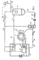
- FIGURE 1 diagrammatically illustrates a compressor of eccentric rotor sliding vane type which includes a stator 2 within which a rotor 4 is eccentrically rotatably mounted.
- the stator and rotor together define a crescent shaped working space which is divided into working cells by a number, in this case 8, of vanes 6 which are slidably accommodated in a respective longitudinal slot in the rotor.
- the construction and operation of this rotor/stator unit are conventional and will therefore not be described in more detail.
- the stator has an inlet 8, an outlet 10 and one or more oil injection orifices 12 situated between the inlet and the outlet with respect to the intended direction of rotation of the rotor.
- the stator outlet 10 communicates with a primary oil reservoir 14 via a non return valve 16, the reservoir 14 accommodating a conventional coalescing element 18 and communicating with a supply line 20 via a further non-return valve 22.
- the lower end of the primary reservoir 14 communicates with the oil injection orifices 12 via a line 24 which includes an oil cooler 26 and an oil filter 28, which are conventional and will therefore not be described, and a pilot operated shut-off valve 30.
- the stator inlet 8 is controlled by a pilot operated shut-off valve 32 which is biased into the open position by a return spring 34 and is accommodated within an inlet housing 36.
- the stator outlet 10 also communicates with the inlet housing 36 by means of a line 38 which is controlled by a further pilot shut-off valve 40.
- the inlet housing 36 communicates with the atmosphere via a conventional air filter 42, and constitutes a secondary or auxiliary oil reservoir the base of which communicates with the oil injection orifices 12 via a line 44 which includes a non-return valve 46 and a further oil cooler 48.
- the compressor also includes a pilot control system comprising a pressure sensitive switch 50 which communicates with the supply line 20 and is thus responsive to the pressure within the primary reservoir 14 and which is connected to a solenoid operated shut-off valve 52 situated in a line 54 which extends between the primary reservoir 14 and the pilot control port of each of the three pilot controlled valves 30, 32, and 40.
- a pilot control system comprising a pressure sensitive switch 50 which communicates with the supply line 20 and is thus responsive to the pressure within the primary reservoir 14 and which is connected to a solenoid operated shut-off valve 52 situated in a line 54 which extends between the primary reservoir 14 and the pilot control port of each of the three pilot controlled valves 30, 32, and 40.
- the pilot control valves 30 and 32 are open whilst the pilot control valve 40 and solenoid operated valve 52 are closed.
- the rotor rotates within the stator and draws air in through the air filter 42 which passes around the open valve 32 and is compressed in the crescent shaped working space within the stator.
- the compressed air and oil mixture all passes through the non-return valve 16 into the primary reservoir 14 since the valve 40 is closed, and the majority of the oil is instantly deposited in the primary reservoir 14 whilst the remainder is coalesced by the element 18.
- stator The interior of the stator is thus isolated from the remainder of the compressor by the valve 32 which seals its inlet, the valve 30 which seals the oil communication with the primary reservoir and the non-return valve 16 which ensures that the primary reservoir is not vented down to atmospheric pressure as well.
- the residual air and oil within the stator passes through the line 38 and the valve 40 into the inlet housing 36 which constitutes the secondary reservoir and the entrained oil droplets are there deposited.
- slightly sub-atmospheric pressure at the oil injection orifices 12 a small amount of oil is constantly withdrawn from the housing 36 and injected through the orifices 12 which then passes along the line 38 and through the valve 40, and is thus constantly recycled.
- the pressure in the supply line 20 and primary reservoir 14 will rapidly drop and when it has reached a further predetermined value, the pressure switch closes the solenoid valve 52 which permits the valve 32 to return to its open position under the action of its return spring, and the compressor then resumes normal operation with the valve 30 opening and the valve 40 closing. If the compressed air load did not in fact drop to zero, but was merely some fractionof the full rated load, the compressor will cycle between the operating and idling modes for relative times determined by the actual compressed air requirement.
- the compressor in accordance with the present invention consumes only between about 10 and 20% of its full rated power when it is operating in the idling mode, and further that the stator can be fully depressurised and thus operating in its idling mode within about 1 second of the predetermined excess pressure being measured by the pressure sensor 50.
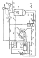
- FIGURE 2 The modified construction illustrated in FIGURE 2 is very similar to that of FIGURE 1 and the same reference numerals are used to designate similar components.
- the valve 32 instead of having only two positions,namely a fully open position and a fully closed position, the valve 32 constitutes an unloader valve whièch-moves progressively to throttle stator inlet 8 under the action of a servo valve 60 which is subjected to the pressure prevailing within the primary reservoir 14.
- the construction and operation of this servo valve is conventional and disclosed in, for instance, British Patent Specification No. 1599319 and will therefore not be described.
- the logic unit switches the solenoid operated valve which in turn switches all the pilot control valves and the compressor then operates in its idling mode.
- a predetermined value which may be at, say, a compressed air load which is 50% of the full rated load
- the logic unit switches the solenoid operated valve which in turn switches all the pilot control valves and the compressor then operates in its idling mode.
- the reduced or subsequently resumed compressed air load will result in a decrease in the pressure prevailing in the primary reservoir, but it will be appreciated that this will not be reflected by an increase in pressure at the stator inlet since when in the idling mode the stator is isolated from the primary reservoir.
- the pressure switch 50 is provided in this embodiment also but its function is merely to return the compressor to normal operation when the pressure in the primary reservoir 14 sinks to a predetermined value.
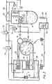
- FIG. 3 The construction illustrated in Figure 3 is again very similar to that illustrated in Figure 1 and the same reference numerals are used.
- the valve 32 again only has two positions, as in Figure 1.
- the pilot operated valves are operated by the pressure of the air in the primary reservoir 14 but it will be appreciated that if the compressor operates in the idling mode for a long period of time the pressure in this reservoir may sink due to natural leakage to a value below which it cannot operate the valves. This risk is eliminated in Figure 3 by operating the valves by the pressure of the compressed air at a point downstream of the non-return valve 22.
- valves 30,32 and 40 are controlled by separate solenoid operated valves 70,72 and 74 respectively which in turn are controlled by a micro-processor logic unit 62 connected to the pressure switch 50.
- This permits the valve 30 to be returned to its normal position later, e.g. 5 seconds later, than the valves 32 and 40 after a period of idling operation thereby ensuring that for an initial period of normal operation oil is withdrawn from the secondary reservoir 36 rather than the main reservoir 14.
- the length of the delay is preferably so set that the amount of oil extracted from the secondary reservoir exactly compensates for that additional amount which is injected into it at the beginning of each idling phase.
- valve 40 is arranged to be opened at the beginning of an idling phase slightly after the valve 30 has closed thereby ensuring that the majority of the oil within the stator at the beginning of the idling phase is returned to the primary reservoir rather than the secondary reservoir. This not only helps to alleviate the problem referred to above but also prevents the compressor inlet from "smoking" at the beginning of an idling phase due to a large volume of air-borne oil suddenly being injected into the housing 36.
- the non-return valve 46 in the line 44 is replaced in Figure 3 by a pilot-operated valve 76 which is controlled by the solenoid valve 74 to open and close at the same time as the pilot operated valve 40 so that oil cannot be withdrawn from the secondary reservoir until the valve 40 is open.
- FIG. 1 and 3 differ only in minor features.
- the oil filter 28 is situated downstream of the valve 30 and thus filters oil from both the primary and secondary reservoirs.
- the primary reservoir 14 is divided into two by a partition 78 and is provided upstream of the coalescing element 18 with a plurality of baffle plates 80 against which the compressed air impinges thereby depositing the majority of the entrained oil droplets. The oil separation is thus performed in two distinct stages, as is conventional.
Landscapes
- Engineering & Computer Science (AREA)
- Mechanical Engineering (AREA)
- General Engineering & Computer Science (AREA)
- Applications Or Details Of Rotary Compressors (AREA)
- Structures Of Non-Positive Displacement Pumps (AREA)
- Rotary Pumps (AREA)
- Compressors, Vaccum Pumps And Other Relevant Systems (AREA)
Priority Applications (1)
| Application Number | Priority Date | Filing Date | Title |
|---|---|---|---|
| AT84306584T ATE35720T1 (de) | 1983-09-28 | 1984-09-27 | Umlaufverdichter der verdraengerbauart. |
Applications Claiming Priority (2)
| Application Number | Priority Date | Filing Date | Title |
|---|---|---|---|
| GB8326017 | 1983-09-28 | ||
| GB08326017A GB2147363B (en) | 1983-09-28 | 1983-09-28 | Positive displacement rotary compressors |
Publications (3)
| Publication Number | Publication Date |
|---|---|
| EP0142926A2 true EP0142926A2 (de) | 1985-05-29 |
| EP0142926A3 EP0142926A3 (en) | 1986-10-08 |
| EP0142926B1 EP0142926B1 (de) | 1988-07-13 |
Family
ID=10549442
Family Applications (1)
| Application Number | Title | Priority Date | Filing Date |
|---|---|---|---|
| EP84306584A Expired EP0142926B1 (de) | 1983-09-28 | 1984-09-27 | Umlaufverdichter der Verdrängerbauart |
Country Status (7)
| Country | Link |
|---|---|
| US (1) | US4553906A (de) |
| EP (1) | EP0142926B1 (de) |
| JP (1) | JPS60101297A (de) |
| AT (1) | ATE35720T1 (de) |
| DE (1) | DE3472705D1 (de) |
| ES (1) | ES8506145A1 (de) |
| GB (1) | GB2147363B (de) |
Cited By (1)
| Publication number | Priority date | Publication date | Assignee | Title |
|---|---|---|---|---|
| GB2269424A (en) * | 1992-08-07 | 1994-02-09 | American Standard Inc | Preventing oil supply to screw compressor on shutdown |
Families Citing this family (21)
| Publication number | Priority date | Publication date | Assignee | Title |
|---|---|---|---|---|
| GB2164095B (en) * | 1984-09-05 | 1988-01-27 | Hydrovane Compressor | Rotary air compressors |
| GB2167130B (en) * | 1984-11-19 | 1988-01-13 | Hydrovane Compressor | Rotary positive displacement air compressor |
| SE451394B (sv) * | 1986-01-31 | 1987-10-05 | Stal Refrigeration Ab | Forfarande for reglering av en rotationskompressor |
| US4762469A (en) * | 1986-03-03 | 1988-08-09 | American Standard Inc. | Rotor anti-reverse rotation arrangement in a screw compressor |
| US4768355A (en) * | 1987-01-27 | 1988-09-06 | Ford Motor Company | Accumulator with refrigerant processing cartridge for automotive air conditioning system |
| US4800737A (en) * | 1987-04-17 | 1989-01-31 | Ford Motor Company | Automotive air conditioning system accumulator with refrigerant processing cartridge including evaporator pressure regulator |
| US5033944A (en) * | 1989-09-07 | 1991-07-23 | Unotech Corporation | Lubricant circuit for a compressor unit and process of circulating lubricant |
| WO1991005167A1 (en) * | 1989-09-27 | 1991-04-18 | Unotech Corporation | Lubricant circuit for a compressor unit and processes of circulating lubricant |
| AT401088B (de) * | 1990-03-16 | 1996-06-25 | Hoerbiger Ventilwerke Ag | Verfahren zum stufenlosen regeln der fördermenge von kolbenverdichtern und einrichtung zur durchführung des verfahrens |
| GB2257751B (en) * | 1991-07-16 | 1994-08-17 | Rotocold Holdings Ltd | Rotary vane gas compressors |
| US5803715A (en) * | 1991-10-14 | 1998-09-08 | Cash Engineering Research Pty. Ltd. | Inlet control combination for a compressor system |
| ATE160207T1 (de) * | 1992-02-14 | 1997-11-15 | Cash Eng Res | Flüssigkeitsdurchströmtes verdichtersystem unter verwendung eines flüssigkeitsabscheiders |
| JPH0712072A (ja) * | 1993-06-23 | 1995-01-17 | Toyota Autom Loom Works Ltd | ベーン圧縮機 |
| GB2344856B (en) | 1998-12-18 | 2002-12-18 | Ingersoll Rand Company Ltd | Method of operating compressor |
| US6257840B1 (en) | 1999-11-08 | 2001-07-10 | Copeland Corporation | Scroll compressor for natural gas |
| JP4666871B2 (ja) * | 2000-04-11 | 2011-04-06 | サルエアー コーポレイション | 一体型コンプレッサドライヤ装置 |
| US6846348B2 (en) * | 2000-04-11 | 2005-01-25 | Cash Engineering Research Pty Ltd. | Compressor/drier system and absorber therefor |
| BE1015079A4 (nl) * | 2002-08-22 | 2004-09-07 | Atlas Copco Airpower Nv | Compressor met drukontlasting. |
| RU2266430C2 (ru) * | 2003-11-26 | 2005-12-20 | Открытое акционерное общество Научно-производственное объединение "Искра" | Агрегат компрессорный ротационно-пластинчатый |
| GB2596608A (en) * | 2020-06-29 | 2022-01-05 | Leybold France S A S | Supplying lubricant to a lubricant sealed pump |
| GB202219367D0 (en) * | 2022-12-21 | 2023-02-01 | Atlas Copco Airpower Nv | A pressure-controlled mechanical valve for selectively diverting scavenged lubricant within a vaccum pumping system |
Family Cites Families (8)
| Publication number | Priority date | Publication date | Assignee | Title |
|---|---|---|---|---|
| CH194825A (de) * | 1936-11-18 | 1937-12-31 | Escher Wyss Maschf Ag | Einrichtung zur Sicherung der Schmierung von Drehkolbenverdichtern. |
| US3395856A (en) * | 1966-12-30 | 1968-08-06 | Caterpillar Tractor Co | Air compressor oil control system |
| US3448916A (en) * | 1967-06-16 | 1969-06-10 | Ingersoll Rand Co | Unloading system for compressors |
| FR1574479A (de) * | 1968-07-17 | 1969-07-11 | ||
| US4068980A (en) * | 1976-10-01 | 1978-01-17 | Gardner-Denver Company | Compressor startup control |
| GB1599319A (en) * | 1977-05-25 | 1981-09-30 | Hydrovane Compressor | Rotary compressors |
| IT1103276B (it) * | 1977-05-25 | 1985-10-14 | Hydrovane Compressor | Compressore a capsulismo a tenuta di olio |
| GB1599878A (en) * | 1977-07-05 | 1981-10-07 | Pidgeon H H J | Oil-injected rotary compressors |
-
1983
- 1983-09-28 GB GB08326017A patent/GB2147363B/en not_active Expired
-
1984
- 1984-09-26 US US06/654,678 patent/US4553906A/en not_active Expired - Fee Related
- 1984-09-27 AT AT84306584T patent/ATE35720T1/de not_active IP Right Cessation
- 1984-09-27 EP EP84306584A patent/EP0142926B1/de not_active Expired
- 1984-09-27 ES ES536312A patent/ES8506145A1/es not_active Expired
- 1984-09-27 DE DE8484306584T patent/DE3472705D1/de not_active Expired
- 1984-09-28 JP JP59203961A patent/JPS60101297A/ja active Pending
Cited By (1)
| Publication number | Priority date | Publication date | Assignee | Title |
|---|---|---|---|---|
| GB2269424A (en) * | 1992-08-07 | 1994-02-09 | American Standard Inc | Preventing oil supply to screw compressor on shutdown |
Also Published As
| Publication number | Publication date |
|---|---|
| US4553906A (en) | 1985-11-19 |
| GB2147363A (en) | 1985-05-09 |
| GB8326017D0 (en) | 1983-11-02 |
| EP0142926B1 (de) | 1988-07-13 |
| ES536312A0 (es) | 1985-06-16 |
| ES8506145A1 (es) | 1985-06-16 |
| GB2147363B (en) | 1987-02-11 |
| JPS60101297A (ja) | 1985-06-05 |
| DE3472705D1 (en) | 1988-08-18 |
| ATE35720T1 (de) | 1988-07-15 |
| EP0142926A3 (en) | 1986-10-08 |
Similar Documents
| Publication | Publication Date | Title |
|---|---|---|
| EP0142926B1 (de) | Umlaufverdichter der Verdrängerbauart | |
| US4063855A (en) | Compressor capacity and lubrication control system | |
| US3961862A (en) | Compressor control system | |
| US3788776A (en) | Compressor unloading control | |
| US3482768A (en) | Compressor control system | |
| EP1552155B1 (de) | Kompressor mit leistungsregelung | |
| US4388046A (en) | Rotary compressors | |
| US4270885A (en) | Unloading means for a gas compressor | |
| US4642033A (en) | Positive displacement air compressors | |
| US4525129A (en) | Oil-sealed vacuum pump | |
| JPH0324594B2 (de) | ||
| US4861246A (en) | Injected compressor with liquid switch | |
| US3632231A (en) | Suction pressure relieving system for a rotary vane compressor | |
| GB1512332A (en) | Oil-cooled compressors | |
| CN212028554U (zh) | 一种加载调节阀 | |
| JP2952377B2 (ja) | 圧縮機における容量制御装置 | |
| JP2599728B2 (ja) | 油冷式スクリュー圧縮機の給油装置 | |
| JP2584173B2 (ja) | 油冷式圧縮機の運転方法 | |
| US3207424A (en) | Flow control for screw compressors | |
| JPH10196575A (ja) | 油冷却スクリュ圧縮機の給油構造 | |
| JPH0972289A (ja) | スクリュ二段圧縮機 | |
| JPH0139914Y2 (de) | ||
| JPH0241360Y2 (de) | ||
| GB1599319A (en) | Rotary compressors | |
| SU1707258A1 (ru) | Способ защиты винтового компрессорного агрегата |
Legal Events
| Date | Code | Title | Description |
|---|---|---|---|
| PUAI | Public reference made under article 153(3) epc to a published international application that has entered the european phase |
Free format text: ORIGINAL CODE: 0009012 |
|
| AK | Designated contracting states |
Designated state(s): AT BE CH DE FR GB IT LI LU NL SE |
|
| RAP1 | Party data changed (applicant data changed or rights of an application transferred) |
Owner name: THE HYDROVANE COMPRESSOR COMPANY LIMITED |
|
| PUAL | Search report despatched |
Free format text: ORIGINAL CODE: 0009013 |
|
| AK | Designated contracting states |
Kind code of ref document: A3 Designated state(s): AT BE CH DE FR GB IT LI LU NL SE |
|
| 17P | Request for examination filed |
Effective date: 19860915 |
|
| 17Q | First examination report despatched |
Effective date: 19871130 |
|
| ITF | It: translation for a ep patent filed | ||
| GRAA | (expected) grant |
Free format text: ORIGINAL CODE: 0009210 |
|
| AK | Designated contracting states |
Kind code of ref document: B1 Designated state(s): AT BE CH DE FR GB IT LI LU NL SE |
|
| PG25 | Lapsed in a contracting state [announced via postgrant information from national office to epo] |
Ref country code: LI Effective date: 19880713 Ref country code: CH Effective date: 19880713 Ref country code: AT Effective date: 19880713 |
|
| REF | Corresponds to: |
Ref document number: 35720 Country of ref document: AT Date of ref document: 19880715 Kind code of ref document: T |
|
| REF | Corresponds to: |
Ref document number: 3472705 Country of ref document: DE Date of ref document: 19880818 |
|
| ET | Fr: translation filed | ||
| REG | Reference to a national code |
Ref country code: CH Ref legal event code: PL |
|
| PLBE | No opposition filed within time limit |
Free format text: ORIGINAL CODE: 0009261 |
|
| STAA | Information on the status of an ep patent application or granted ep patent |
Free format text: STATUS: NO OPPOSITION FILED WITHIN TIME LIMIT |
|
| 26N | No opposition filed | ||
| PG25 | Lapsed in a contracting state [announced via postgrant information from national office to epo] |
Ref country code: GB Effective date: 19890927 |
|
| GBPC | Gb: european patent ceased through non-payment of renewal fee | ||
| ITTA | It: last paid annual fee | ||
| EPTA | Lu: last paid annual fee | ||
| EAL | Se: european patent in force in sweden |
Ref document number: 84306584.8 |
|
| PGFP | Annual fee paid to national office [announced via postgrant information from national office to epo] |
Ref country code: SE Payment date: 20030904 Year of fee payment: 20 |
|
| PGFP | Annual fee paid to national office [announced via postgrant information from national office to epo] |
Ref country code: FR Payment date: 20030909 Year of fee payment: 20 |
|
| PGFP | Annual fee paid to national office [announced via postgrant information from national office to epo] |
Ref country code: NL Payment date: 20030922 Year of fee payment: 20 |
|
| PGFP | Annual fee paid to national office [announced via postgrant information from national office to epo] |
Ref country code: LU Payment date: 20030929 Year of fee payment: 20 |
|
| PGFP | Annual fee paid to national office [announced via postgrant information from national office to epo] |
Ref country code: DE Payment date: 20031009 Year of fee payment: 20 |
|
| PGFP | Annual fee paid to national office [announced via postgrant information from national office to epo] |
Ref country code: BE Payment date: 20031203 Year of fee payment: 20 |
|
| PG25 | Lapsed in a contracting state [announced via postgrant information from national office to epo] |
Ref country code: NL Free format text: LAPSE BECAUSE OF EXPIRATION OF PROTECTION Effective date: 20040927 Ref country code: LU Free format text: LAPSE BECAUSE OF EXPIRATION OF PROTECTION Effective date: 20040927 |
|
| BE20 | Be: patent expired |
Owner name: THE *HYDROVANE COMPRESSOR CY LTD Effective date: 20040927 |
|
| EUG | Se: european patent has lapsed | ||
| NLV7 | Nl: ceased due to reaching the maximum lifetime of a patent |
Effective date: 20040927 |