EP0142712A1 - Steuerungssystem für mehrfachen Gelenkarmmechanismus - Google Patents
Steuerungssystem für mehrfachen Gelenkarmmechanismus Download PDFInfo
- Publication number
- EP0142712A1 EP0142712A1 EP84112503A EP84112503A EP0142712A1 EP 0142712 A1 EP0142712 A1 EP 0142712A1 EP 84112503 A EP84112503 A EP 84112503A EP 84112503 A EP84112503 A EP 84112503A EP 0142712 A1 EP0142712 A1 EP 0142712A1
- Authority
- EP
- European Patent Office
- Prior art keywords
- arm
- jointed
- control
- arm mechanism
- control apparatus
- Prior art date
- Legal status (The legal status is an assumption and is not a legal conclusion. Google has not performed a legal analysis and makes no representation as to the accuracy of the status listed.)
- Granted
Links
- 230000007246 mechanism Effects 0.000 title claims abstract description 38
- 238000001514 detection method Methods 0.000 claims description 3
- 230000002708 enhancing effect Effects 0.000 abstract 1
- 238000010586 diagram Methods 0.000 description 4
- 230000008878 coupling Effects 0.000 description 3
- 238000010168 coupling process Methods 0.000 description 3
- 238000005859 coupling reaction Methods 0.000 description 3
- 230000008859 change Effects 0.000 description 2
- 238000006073 displacement reaction Methods 0.000 description 2
- 239000011159 matrix material Substances 0.000 description 2
- 230000004044 response Effects 0.000 description 2
- 230000015556 catabolic process Effects 0.000 description 1
- 238000006731 degradation reaction Methods 0.000 description 1
Images


Classifications
-
- G—PHYSICS
- G05—CONTROLLING; REGULATING
- G05B—CONTROL OR REGULATING SYSTEMS IN GENERAL; FUNCTIONAL ELEMENTS OF SUCH SYSTEMS; MONITORING OR TESTING ARRANGEMENTS FOR SUCH SYSTEMS OR ELEMENTS
- G05B19/00—Programme-control systems
- G05B19/02—Programme-control systems electric
- G05B19/18—Numerical control [NC], i.e. automatically operating machines, in particular machine tools, e.g. in a manufacturing environment, so as to execute positioning, movement or co-ordinated operations by means of programme data in numerical form
- G05B19/414—Structure of the control system, e.g. common controller or multiprocessor systems, interface to servo, programmable interface controller
- G05B19/4141—Structure of the control system, e.g. common controller or multiprocessor systems, interface to servo, programmable interface controller characterised by a controller or microprocessor per axis
-
- G—PHYSICS
- G05—CONTROLLING; REGULATING
- G05B—CONTROL OR REGULATING SYSTEMS IN GENERAL; FUNCTIONAL ELEMENTS OF SUCH SYSTEMS; MONITORING OR TESTING ARRANGEMENTS FOR SUCH SYSTEMS OR ELEMENTS
- G05B2219/00—Program-control systems
- G05B2219/30—Nc systems
- G05B2219/37—Measurements
- G05B2219/37572—Camera, tv, vision
-
- G—PHYSICS
- G05—CONTROLLING; REGULATING
- G05B—CONTROL OR REGULATING SYSTEMS IN GENERAL; FUNCTIONAL ELEMENTS OF SUCH SYSTEMS; MONITORING OR TESTING ARRANGEMENTS FOR SUCH SYSTEMS OR ELEMENTS
- G05B2219/00—Program-control systems
- G05B2219/30—Nc systems
- G05B2219/42—Servomotor, servo controller kind till VSS
- G05B2219/42162—Model reference adaptive control MRAC, correction fictive-real error, position
-
- G—PHYSICS
- G05—CONTROLLING; REGULATING
- G05B—CONTROL OR REGULATING SYSTEMS IN GENERAL; FUNCTIONAL ELEMENTS OF SUCH SYSTEMS; MONITORING OR TESTING ARRANGEMENTS FOR SUCH SYSTEMS OR ELEMENTS
- G05B2219/00—Program-control systems
- G05B2219/30—Nc systems
- G05B2219/45—Nc applications
- G05B2219/45083—Manipulators, robot
-
- G—PHYSICS
- G05—CONTROLLING; REGULATING
- G05B—CONTROL OR REGULATING SYSTEMS IN GENERAL; FUNCTIONAL ELEMENTS OF SUCH SYSTEMS; MONITORING OR TESTING ARRANGEMENTS FOR SUCH SYSTEMS OR ELEMENTS
- G05B2219/00—Program-control systems
- G05B2219/30—Nc systems
- G05B2219/49—Nc machine tool, till multiple
- G05B2219/49143—Obstacle, collision avoiding control, move so that no collision occurs
Definitions
- the present invention relates to a control apparatus for controlling a multi-jointed arm mechanism which is composed of a plurality of arm elements associated with one another and joints for coupling them.
- a multi-jointed arm mechanism which consists of a plurality of arm elements associated with one another and joints for coupling them is, for example, the multi- articulated arm mechanism of a robot as disclosed in the official gazette of U. S. Patent No. 4221997.
- the arm elements are associated with one another, so that the outputs of the respective arm elements need to be adjusted while holding cooperative relations with the other arm elements associated with one another.
- a concentrated type control apparatus comprising a single calculator which integrates and controls the plurality of arm elements.
- the concentrated type control apparatus applies the signals from the sensor to the single calculator, which computes on the basis of the input signals the request outputs of all of the plurality of arm elements constituting the multi-jointed arm mechanism and associated with one another, and it supplies the respective arm elements with the computed values as control signals and controls the respective arm elements so as to agree with the target values thereof.
- the present invention for accomplishing the object consists, in a multi-jointed arm mechanism having a plurality of arm elements which are respectively driven by actuators, in comprising means to detect information on a control error of the multi-jointed arm mechanism relative to a target position thereof, and control means connected to the actuator of at least one of the arm elements and to compute an arm element movement magnitude for making zero a difference between the control error information from the detection means produced by a movement of the arm element and predictive information on the control error computed on the basis of movement information of the arm element and to deliver it to the corresponding actuator.
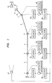
- Fig. 1 shows a multi-jointed arm mechanism which is equipped with an example of the control apparatus of the present invention.
- the multi-jointed arm mechanism A is installed on, for example, a movable base B.
- This multi-jointed arm mechanism A is constructed of a first arm element 2 which is turnably mounted on the base B by a first joint 1, a second arm element 4 which is turnably mounted on the fore end of the first arm element 2 by a second joint 3, a third arm element 6 which is turnably mounted on the fore end of the second arm element 4 by a third joint 5, a fourth arm element 8 which is turnably mounted on the fore end of the third arm element 6 by a fourth joint 7, and a grip 9 which is provided at the fore end of the fourth arm element 8.
- the arm elements 2, 4, 6 and 8 constituting the multi-jointed arm mechanism A are respectively driven by actuators 11 - 14 which shafts of the are disposed on the respective joints 1, 3, 5 and 7. / These actuators 11 - 14 can be constructed of, for example, stepping motors.
- the shafts of the joints 1, 3, 5 and 7 are respectively furnished with detectors 15 - 18 which detect the movement magnitudes ⁇ 1 - ⁇ 4 of the arm elements 2, 4, 6 and 8 coupled to the respective joints 1, 3, 5 and 7.
- the detection signals ⁇ 1 - B 4 from the respective detectors 15 - 18 are negatively fed back to comparators 19 - 22 which constitute the drive control systems of the corresponding arm elements 2, 4, 6 and 8.
- comparators 19 - 22 compare target movement magnitudes ⁇ 1 '- ⁇ 4 ' from calculators 23 - 26 included in the drive control systems, with the actual movement magnitudes ⁇ 1 - e 4 from the detectors 15 - 18, and they deliver the errors e 1 - e 4 between them to the actuators 11 - 14, respectively.
- the aforementioned calculators 23 - 26, which are respectively incorporated in the drive control systems of the arm elements 2, 4, 6 and 8, are all supplied with a signal concerning the positional deviation magnitude (control error magnitude) E of the grip 9 relative to the object 10, the signal being delivered from an input device 27.
- the input device 27 mentioned above can be constructed of a television camera or the like.
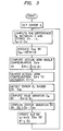
- Numeral 28 an arithmetic unit which computes the compensation value / ⁇ x of the corresponding one of the movement magnitudes 8 1 - ⁇ 4 of the respective arm elements 2, 4, 6 and 8.
- the arithmetic unit 28 for the arm compensation value computes the compensation value ⁇ x of the corresponding one of the actual movement magnitudes 8 1 - ⁇ 4 of the respective arm elements 2, 4, 6 and 8 on the basis of the control erorr magnitude E of the grip 9 relative to the object 10 as delivered from the input device 27.
- the compensation value ⁇ x can be computed with the following equation (1): where ⁇ , ⁇ : coefficients,
- ⁇ proportion coefficient for compensation, which is a plus constant smaller than 1.
- Numeral 29 designates a delay circuit.
- Numeral 30 designates an adder, which adds the last control error E and a control error E I obtained with the arm compensation value ⁇ x and thus evaluates the true variation oe between them.
- Numeral 31 indicates an-arithmetic unit for a predictive variation, which computes the predictive variation ⁇ e x of the control error E on the basis of the aforementioned compensation value ⁇ x .
- This predictive variation ⁇ e x can be computed with the following equation (2): where ⁇ , ⁇ : coefficients.
- Numeral 33 denotes an arithmetic unit for updating the coefficients, which computes the coefficients ⁇ and p in the operating equation of the predictive-variation arithmetic unit 31, i. e., the foregoing equation (2) and the operating equation of the arm-compensation-value arithmetic unit 28, i.
- the grip 9 of the multi-jointed arm mechanism A involves a control error E relative to the object 10 to be grasped.
- the control error of the grip 9 relative to the object 10 before changing the first arm element 2 by the angle as stated above, is denoted by E 0 .
- the control error E of the grip 9 relative to the object 10, ascribable to the change of the first arm element 2 by the angle ⁇ , is applied to the respective calculators 23 - 26 by the vision device 27. Since, in this case, only the first arm element 2 has been operated as described above, the control error E is used in only the calculator 23.
- the predictive-variation arithmetic unit 31 receives the arm compensation angle ⁇ x of the first arm element 2 from the arm-compensation-angle arithmetic unit 28 to be described below and computes a predictive variation ⁇ e x on the basis of Equation (2) mentioned before.
- the arm-compensation-angle arithmetic unit 28 computes an actual arm compensation angle ⁇ x on the basis of Equation (1) mentioned before.
- the actual arm compensation angle ⁇ x is delivered to the actuator 11.
- the first arm element 2 is moved.
- the grip 9 causes a control error E I relative to the object 10.
- the control error E 1 is detected by the vision device 27, and is applied to the adder 30 of the calculator 23.
- the adder 30 evaluates the true variation ⁇ e between this control error E 1 and the last control error E.
- This error variation ⁇ E is applied to the coefficient updating arithmetic unit 33.
- the coefficient updating arithmetic unit 33 computes the updated coefficients ⁇ ' and ⁇ ' of the respective coefficients ⁇ and ⁇ in Equations (1) and (2) on the basis of Equations (3) and (4) mentioned before, and it delivers the updated coefficients ⁇ ' and ⁇ ' to the predicitve-variation arithmetic unit 31 and the arm-compensation-angle arithmetic unit 28 so as to substitute them for the respective coefficients ⁇ and p in the units 31 and 28.
- the predictive-variation arithmetic unit 31 and the arm-compensation-angle arithmetic unit 28 have gotten ready for the next control operations for positioning the grip 9 to the object 10.
- the control apparatus of the present invention consists in evaluating the predictive variation ⁇ e x of the control error of the grip 9 relative to the object 10 on the basis of the angular displacements of the respective arm elements, computing the true variation d e obtained with the angular displacements, and updating the error variation on the basis of the variations ⁇ e x x and ⁇ e.
- the respective arm elements 2, 4, 6 and 8 are cooperatively controlled.
- the control since the control is performed for each of the arm elements 2, 4, 6 and 8, it is possible at a higher speed than in an apparatus having a higher-ranking computer which integratingly controls the respective arm elements 2, 4, 6 and 8.
- Fig. 4 shows another embodiment of the control apparatus of the present invention.
- This embodiment consists in that, in order to increase or decrease control errors attributed to the operations between the respective arm elements 2, 4, 6 and 8, the calculators 23 - 26 corresponding to these arm elements 2, 4, 6 and 8 are connected by communication units 34.
- an error variation ⁇ E 1 caused when another arm element has been changed by ⁇ x1 is applied to the arm-compensation-angle arithmetic unit 2,8 shown in Fig. 2.
- the foregoing equation (1) in the arm-compensation-angle arithmetic unit 28 needs to be altered to the following equation (5):
- the coefficients of Equation (2) for the predictive computation are updated on the basis of data or are learnt, they may of course be computed beforehand and kept stored.
- the control error of the grip 9 of the multi-jointed arm mechanism A relative to the object 10 is controlled by the use of the positioning error of the fore end of the grip 9.
- the operating region of the multi-jointed arm mechanism A can be secured to a sufficient extent, so that the control apparatus of the present invention is applicable.
- this situation can be coped with in such a way that the control apparatus of the present invention described above is supplied with information on the which is approach to the obstacle, of the arm elements located midway of the multi-jointed arm mechanism A. In this case, as illustrated in Fig.
- the intermediate arm element is provided with a sensor 35 for sensing the obstacle B, and a sensed signal S from the sensor 35 is applied to the calculator 25, whereby a movement for preventing the intermediate arm element from moving toward the obstacle B can be compensated for.
- a calculator in this case can be constructed by treating the sensed signal just as the control error of the grip 9 relative to the object 10 is treated in the calculator shown in Fig. 2. Therefore, it shall not be described in detail.
- the calculators 23 - 26 are disposed for the respective actuators 11 - 14, they may well be constructed into a single calculator. Besides, the calculators need not be connected to all the actuators 11 - 14.
- calculators for controlling the respective calculators of a multi-jointed arm mechanism are connected to the actuators, and the control error of the multi-jointed arm mechanism is applied to the calculators so as to control the respective actuators, so that the arm elements of the multi-jointed arm mechanism can be controlled at high speed.
Landscapes
- Engineering & Computer Science (AREA)
- Computer Hardware Design (AREA)
- Microelectronics & Electronic Packaging (AREA)
- Human Computer Interaction (AREA)
- Manufacturing & Machinery (AREA)
- Physics & Mathematics (AREA)
- General Physics & Mathematics (AREA)
- Automation & Control Theory (AREA)
- Control Of Position Or Direction (AREA)
- Numerical Control (AREA)
- Manipulator (AREA)
Applications Claiming Priority (2)
| Application Number | Priority Date | Filing Date | Title |
|---|---|---|---|
| JP192352/83 | 1983-10-17 | ||
| JP58192352A JPS6085885A (ja) | 1983-10-17 | 1983-10-17 | 多関節機構の制御装置 |
Publications (2)
| Publication Number | Publication Date |
|---|---|
| EP0142712A1 true EP0142712A1 (de) | 1985-05-29 |
| EP0142712B1 EP0142712B1 (de) | 1989-03-29 |
Family
ID=16289845
Family Applications (1)
| Application Number | Title | Priority Date | Filing Date |
|---|---|---|---|
| EP84112503A Expired EP0142712B1 (de) | 1983-10-17 | 1984-10-17 | Steuerungssystem für mehrfachen Gelenkarmmechanismus |
Country Status (4)
| Country | Link |
|---|---|
| US (1) | US4604561A (de) |
| EP (1) | EP0142712B1 (de) |
| JP (1) | JPS6085885A (de) |
| DE (1) | DE3477523D1 (de) |
Cited By (1)
| Publication number | Priority date | Publication date | Assignee | Title |
|---|---|---|---|---|
| WO2023143810A1 (en) * | 2022-01-28 | 2023-08-03 | Kassow Robots Aps | Calculations in a robot |
Families Citing this family (18)
| Publication number | Priority date | Publication date | Assignee | Title |
|---|---|---|---|---|
| DE3501968A1 (de) * | 1985-01-22 | 1986-07-24 | Siemens AG, 1000 Berlin und 8000 München | Steuerungseinrichtung fuer eine mehrachsige werkzeugmaschine |
| EP0196483B1 (de) * | 1985-03-29 | 1988-09-21 | Siemens Aktiengesellschaft | Lageregelsystem für rechnergesteuerte Arbeitsmaschinen |
| US4789940A (en) * | 1985-08-30 | 1988-12-06 | Texas Instruments Incorporated | Method and apparatus for filtering reflections from direct images for mobile robot navigation |
| JPS62199385A (ja) * | 1986-02-27 | 1987-09-03 | 株式会社東芝 | マニピユレ−タの駆動装置 |
| JPH0789286B2 (ja) * | 1986-02-28 | 1995-09-27 | 株式会社日立製作所 | 多関節マニピユレ−タの作業原点決定方法 |
| US4698572A (en) * | 1986-04-04 | 1987-10-06 | Westinghouse Electric Corp. | Kinematic parameter identification for robotic manipulators |
| US4864206A (en) * | 1986-11-20 | 1989-09-05 | Westinghouse Electric Corp. | Multiaxis robot control having improved energy monitoring system for protecting robots against joint motor overload |
| US4716350A (en) * | 1986-12-08 | 1987-12-29 | Ford Motor Company | Method to avoid singularity in a robot mechanism |
| DE3866203D1 (de) * | 1987-09-28 | 1991-12-19 | Siemens Ag | Verfahren zur numerisch gesteuerten lageregelung elektromotorisch angetriebener achsen. |
| JPH0760339B2 (ja) * | 1987-11-30 | 1995-06-28 | 工業技術院長 | 制御装置 |
| DE4000348A1 (de) * | 1989-03-06 | 1990-09-13 | Hewlett Packard Co | Vorrichtung und verfahren zum ueberwachen der bewegungen eines vielgelenkigen roboters |
| US5055755A (en) * | 1989-05-31 | 1991-10-08 | Kabushiki Kaisha Toshiba | Distribution control apparatus |
| JPH0366589A (ja) * | 1989-05-31 | 1991-03-22 | An Ey-Rang | ロボットの駆動制御回路 |
| JP3010583B2 (ja) * | 1989-12-31 | 2000-02-21 | 株式会社エスジー | 複数軸の同調制御方式 |
| WO1996041705A1 (fr) * | 1995-06-13 | 1996-12-27 | Toyo Kohan Co., Ltd. | Procede de prevention des perturbations concernant des robots industriels |
| DE19650878C1 (de) * | 1996-12-07 | 1998-07-30 | Richter Hans | Verfahren zum Regeln der Bewegungen mindestens eines Antriebselements eines Industrieroboters |
| US6212968B1 (en) * | 1998-07-29 | 2001-04-10 | Janome Sewing Machine Co., Ltd, | SCARA robot |
| US9849926B2 (en) * | 2014-07-23 | 2017-12-26 | Boston Dynamics, Inc. | Predictively adjustable hydraulic pressure rails |
Citations (5)
| Publication number | Priority date | Publication date | Assignee | Title |
|---|---|---|---|---|
| US3639823A (en) * | 1968-11-19 | 1972-02-01 | Acec | Fine and coarse position control device |
| US4221997A (en) * | 1978-12-18 | 1980-09-09 | Western Electric Company, Incorporated | Articulated robot arm and method of moving same |
| WO1983001520A1 (en) * | 1981-10-26 | 1983-04-28 | Us Robots Inc | Robot arm controller with common bus memory |
| EP0111064A2 (de) * | 1982-09-14 | 1984-06-20 | Vickers Incorporated | Leistungsregelsystem |
| EP0113010A1 (de) * | 1982-11-30 | 1984-07-11 | Siemens Aktiengesellschaft | Robotersteuerung |
Family Cites Families (8)
| Publication number | Priority date | Publication date | Assignee | Title |
|---|---|---|---|---|
| US3538315A (en) * | 1967-04-17 | 1970-11-03 | Pratt & Whitney Inc | Numerical control system |
| US3665168A (en) * | 1970-12-18 | 1972-05-23 | Gen Electric | Adaptively controlled position prediction system |
| US3758762A (en) * | 1972-07-10 | 1973-09-11 | Leeds & Northrup Co | Decoupled feedforward-feedback control system |
| JPS5413883A (en) * | 1977-07-04 | 1979-02-01 | Hitachi Ltd | Abnormalness detector of automatic controller |
| US4201937A (en) * | 1978-04-07 | 1980-05-06 | Unimation, Inc. | Control apparatus for programmable manipulator |
| SU1055863A1 (ru) * | 1978-09-06 | 1983-11-23 | Предприятие П/Я М-5973 | Способ управлени буровым агрегатом и устройство дл его осуществлени |
| JPS5840761B2 (ja) * | 1978-12-20 | 1983-09-07 | 工業技術院長 | 人間腕形マニピュレ−タの制御装置 |
| JPS58217294A (ja) * | 1982-06-07 | 1983-12-17 | 株式会社日立製作所 | 産業用ロボツトの安全装置 |
-
1983
- 1983-10-17 JP JP58192352A patent/JPS6085885A/ja active Pending
-
1984
- 1984-10-17 US US06/661,958 patent/US4604561A/en not_active Expired - Fee Related
- 1984-10-17 EP EP84112503A patent/EP0142712B1/de not_active Expired
- 1984-10-17 DE DE8484112503T patent/DE3477523D1/de not_active Expired
Patent Citations (5)
| Publication number | Priority date | Publication date | Assignee | Title |
|---|---|---|---|---|
| US3639823A (en) * | 1968-11-19 | 1972-02-01 | Acec | Fine and coarse position control device |
| US4221997A (en) * | 1978-12-18 | 1980-09-09 | Western Electric Company, Incorporated | Articulated robot arm and method of moving same |
| WO1983001520A1 (en) * | 1981-10-26 | 1983-04-28 | Us Robots Inc | Robot arm controller with common bus memory |
| EP0111064A2 (de) * | 1982-09-14 | 1984-06-20 | Vickers Incorporated | Leistungsregelsystem |
| EP0113010A1 (de) * | 1982-11-30 | 1984-07-11 | Siemens Aktiengesellschaft | Robotersteuerung |
Cited By (1)
| Publication number | Priority date | Publication date | Assignee | Title |
|---|---|---|---|---|
| WO2023143810A1 (en) * | 2022-01-28 | 2023-08-03 | Kassow Robots Aps | Calculations in a robot |
Also Published As
| Publication number | Publication date |
|---|---|
| US4604561A (en) | 1986-08-05 |
| DE3477523D1 (en) | 1989-05-03 |
| EP0142712B1 (de) | 1989-03-29 |
| JPS6085885A (ja) | 1985-05-15 |
Similar Documents
| Publication | Publication Date | Title |
|---|---|---|
| EP0142712A1 (de) | Steuerungssystem für mehrfachen Gelenkarmmechanismus | |
| EP0196417B1 (de) | Regeleinrichtung für ein nichtlineares mechanisches System mit mehreren Freiheitsgraden | |
| EP0321579A1 (de) | Gegliederte robotersteuereinrichtung | |
| US4906907A (en) | Robot system | |
| US4166543A (en) | Method and means for controlling an industrial robot | |
| EP0280324B1 (de) | Nichtlineare Steureungseinheit für einen Manipulator mit mehreren Freiheitsgraden | |
| EP0177919B1 (de) | Verfahren zum Kalibrieren der Transformationsmatrix eines Kraftsensors | |
| EP0375749B1 (de) | Roboterachsensteuerung mit und ohne rückkuppelung | |
| US4362977A (en) | Method and apparatus for calibrating a robot to compensate for inaccuracy of the robot | |
| EP0260326B1 (de) | Regelvorrichtung für einen roboter | |
| US4604716A (en) | Method and apparatus for controlling a robot | |
| WO2009083031A1 (en) | A server controller and a method for controlling a plurality of motors | |
| EP0254211B1 (de) | Positionsausgleichsteuerungssystem für ein Servomechanismusgerät | |
| US4916375A (en) | Servomotor control apparatus | |
| EP0292574B1 (de) | Numerische regelvorrichtung | |
| EP0465661B1 (de) | Verfahren und Vorrichtung zum Steuern eines Gelenkroboters mit Redundanz | |
| GB2099183A (en) | Method for controlling a path of a robot and apparatus therefor | |
| Hähn et al. | Hybrid compliance compensation for path accuracy enhancement in robot machining | |
| US4549261A (en) | Hybrid analog control structure | |
| CA1246636A (en) | Control apparatus for multi-jointed arm mechanism | |
| EP0356133B1 (de) | Servo-Steuerungsgerät | |
| GB2146801A (en) | Control of robots | |
| EP0312602A1 (de) | Vorrichtung zur steuerung eines roboters mit biegsamen armen | |
| JPS6316982A (ja) | 多関節マニピユレ−タの制御装置 | |
| CN117464661A (zh) | 基于动力学转矩补偿的控制方法及控制装置 |
Legal Events
| Date | Code | Title | Description |
|---|---|---|---|
| PUAI | Public reference made under article 153(3) epc to a published international application that has entered the european phase |
Free format text: ORIGINAL CODE: 0009012 |
|
| AK | Designated contracting states |
Designated state(s): DE FR GB IT |
|
| 17P | Request for examination filed |
Effective date: 19850530 |
|
| 17Q | First examination report despatched |
Effective date: 19870331 |
|
| GRAA | (expected) grant |
Free format text: ORIGINAL CODE: 0009210 |
|
| AK | Designated contracting states |
Kind code of ref document: B1 Designated state(s): DE FR GB IT |
|
| REF | Corresponds to: |
Ref document number: 3477523 Country of ref document: DE Date of ref document: 19890503 |
|
| ET | Fr: translation filed | ||
| ITF | It: translation for a ep patent filed | ||
| PLBE | No opposition filed within time limit |
Free format text: ORIGINAL CODE: 0009261 |
|
| STAA | Information on the status of an ep patent application or granted ep patent |
Free format text: STATUS: NO OPPOSITION FILED WITHIN TIME LIMIT |
|
| 26N | No opposition filed | ||
| ITTA | It: last paid annual fee | ||
| PGFP | Annual fee paid to national office [announced via postgrant information from national office to epo] |
Ref country code: GB Payment date: 19991007 Year of fee payment: 16 |
|
| PGFP | Annual fee paid to national office [announced via postgrant information from national office to epo] |
Ref country code: FR Payment date: 19991019 Year of fee payment: 16 |
|
| PGFP | Annual fee paid to national office [announced via postgrant information from national office to epo] |
Ref country code: DE Payment date: 19991230 Year of fee payment: 16 |
|
| PG25 | Lapsed in a contracting state [announced via postgrant information from national office to epo] |
Ref country code: GB Free format text: LAPSE BECAUSE OF NON-PAYMENT OF DUE FEES Effective date: 20001017 |
|
| GBPC | Gb: european patent ceased through non-payment of renewal fee |
Effective date: 20001017 |
|
| PG25 | Lapsed in a contracting state [announced via postgrant information from national office to epo] |
Ref country code: FR Free format text: LAPSE BECAUSE OF NON-PAYMENT OF DUE FEES Effective date: 20010629 |
|
| PG25 | Lapsed in a contracting state [announced via postgrant information from national office to epo] |
Ref country code: DE Free format text: LAPSE BECAUSE OF NON-PAYMENT OF DUE FEES Effective date: 20010703 |
|
| REG | Reference to a national code |
Ref country code: FR Ref legal event code: ST |