EP0142687B1 - Device for lubricating a chain - Google Patents
Device for lubricating a chain Download PDFInfo
- Publication number
- EP0142687B1 EP0142687B1 EP84111889A EP84111889A EP0142687B1 EP 0142687 B1 EP0142687 B1 EP 0142687B1 EP 84111889 A EP84111889 A EP 84111889A EP 84111889 A EP84111889 A EP 84111889A EP 0142687 B1 EP0142687 B1 EP 0142687B1
- Authority
- EP
- European Patent Office
- Prior art keywords
- chain
- lubricant
- lubrication
- pump
- coupling
- Prior art date
- Legal status (The legal status is an assumption and is not a legal conclusion. Google has not performed a legal analysis and makes no representation as to the accuracy of the status listed.)
- Expired
Links
Images


Classifications
-
- B—PERFORMING OPERATIONS; TRANSPORTING
- B65—CONVEYING; PACKING; STORING; HANDLING THIN OR FILAMENTARY MATERIAL
- B65G—TRANSPORT OR STORAGE DEVICES, e.g. CONVEYORS FOR LOADING OR TIPPING, SHOP CONVEYOR SYSTEMS OR PNEUMATIC TUBE CONVEYORS
- B65G45/00—Lubricating, cleaning, or clearing devices
- B65G45/02—Lubricating devices
- B65G45/08—Lubricating devices for chains
-
- F—MECHANICAL ENGINEERING; LIGHTING; HEATING; WEAPONS; BLASTING
- F16—ENGINEERING ELEMENTS AND UNITS; GENERAL MEASURES FOR PRODUCING AND MAINTAINING EFFECTIVE FUNCTIONING OF MACHINES OR INSTALLATIONS; THERMAL INSULATION IN GENERAL
- F16N—LUBRICATING
- F16N13/00—Lubricating-pumps
- F16N13/22—Lubricating-pumps with distributing equipment
Definitions
- the invention relates to a device for applying liquid lubricant in shots to a high-speed chain guided by a drive wheel with at least one lubricant outlet nozzle directed against the chain, to which lubricant is supplied by means of at least one cam-actuated lubricant piston pump, each lubricant delivery point having a fixed lubricant piston pump is assigned, with one or more control cams which are carried by a common, axially movable coupling shaft which can be coupled to a drive shaft and a sensor which emits a signal which effects the coupling and uncoupling of the shaft and lubrication of the chain.
- a lubricating device of this type is known from US-A-4 085 821.
- Lubrication of a chain is triggered there by a contact arm, which is pressed down by the hinge pins of the rotating chain and actuates a signal-triggering switch.
- the signal causes a clutch engagement process that connects a motor shaft to a pump shaft.
- the pump shaft has eccentrics, each of which moves a piston upward against the force of a return spring in a lubricant pump when the shaft is rotated, the amount of lubricant in the pump being fed via a line to the lubricant delivery point.
- the lubricating device can only be used for very slow-running chains, since the electric motor driving the pump shaft cannot be synchronized with the running of the chain as required and cannot be adapted to continuously changing chain speeds, so that a targeted application of a limited amount of lubricant to one certain lubrication point is not possible.
- EP-A-63 446 has disclosed a device for lubricating chains, in which the lubricating units and the tank are arranged on a rotating disk or wheel.
- Such lubrication devices are, however, completely unsuitable for lubricating a large number of lubrication points with the smallest amounts of lubricant, since the lubrication units are subject to very large rotational forces. This leads to an uncontrolled idling of the lubricating oil paths and the application nozzles, especially at high chain speeds. It is therefore not possible for a pressure-stable oil column to form in the feed system to the nozzles of the lubrication units, which is, however, absolutely necessary and only allows one to be able to react to the smallest hydraulic piston strokes in rapid succession.
- the invention has for its object to avoid the above disadvantages and to provide a lubricating device which in particular makes it possible to lubricate up to 10,000 lubrication points (chain pins) per minute so that with significantly reduced oil consumption, the chain links only in the area of the chain pin between receive the same amount of lubricant on each side of the pin, the small amount of which can be distributed over as large an area of the chain pin as possible even at high chain speeds.
- This object is achieved in that the drive shaft is driven and synchronized by the torque removed from the chain drive wheel and that all lubricant piston pumps are arranged around the drive shaft and in a radial plane in which the control cams are positioned on the circumference of the drive shaft.
- each lubricant piston pump has a spring-loaded check valve in the intake and high-pressure line, which closes in the intake line against a pre-pressure in this line and is provided with a deflection cam which defines the start of the spray and the end of the spray at the lubricant dispensing point, at least one of which at the same speed as the chain speed of rotating control cams of the coupling shaft coupled via the coupling of the drive shaft to the chain wheel of the chain in the course of rotation, that the sens assigned to the driving chain wheel or determines the number of lubricant delivery points running over the sprocket and forwards them as counting impulses to a lubrication or pause counter containing the number of existing lubricant delivery points, which after counting down the entered number of lubricant delivery points down to zero the impulses for the Releases the lubricating counter and at the same time causes the shafts to be coupled, and that the lubricating counter finally causes the shafts to be uncoupled after the number of lubricant dispensing points entered
- the check valve in the high-pressure line closes the high-pressure side immediately after the working stroke of the pump piston, which reliably prevents the lubricating oil from flowing in.
- a negative pressure is simultaneously created, which opens the check valve in the intake line, causing the cylinder space to be filled with lubricating oil again.
- Automatic operation of the chain lubrication can be achieved by means of the sensor and the lubrication or pause counter, in which the lubrication counter causes the uncoupling and the pause counter to couple the drive shaft to the coupling shaft.
- the two counters receive the pulses via the sensor and thus the exact number of lubrication points passing by.
- the lubrication point counter contains the number of lubrication points to be lubricated during a lubrication cycle
- the pause counter contains the number of lubrication points not to be counted during a break.
- the counters are switched so that when the lubrication point counter counts down from the entered value to zero, the pause counter receives no pulses.
- the actuating device disengages the chain lubrication, and the sensor pulses now reach the pause counter, which is now also counted down to zero from its set value. Then the cycle starts again. In this way, the chain lubrication does not work time-dependent, but controlled by the effective revolutions of the chain to be lubricated.
- the lubricating device has ten lubricant piston pumps lying next to each other on a semicircle at a distance, each with a deflection cam with a starting slope and two control cams rotating at the same speed as the chain speed and fastened on the coupling shaft in such a way that in the course of the rotation, the one control cam detaches the deflection cam of the first and the other control cam is opposite the deflection cam of the last lubricant piston pump.
- High-pressure lubricant piston pumps allow very high cycle sequences, which, however, require a lubricating oil pre-pressure of 2 bar in the intake lines, for example, from a cycle rate of 4000 lubrication pulses per minute.
- the high cycle sequences naturally lead to increased mechanical wear and lower lubrication quality.
- 10,000 lubrication pulses per minute can be easily achieved with just 1,000 cycles per minute of a single unit.
- the hydraulic system is not subject to any rotational forces.
- the chain speed removed from the chain wheel is transmitted during the lubrication phase to the control cam which is fastened to the clutch shaft and which, when it strikes the start slope of the deflection cam of a lubricant pump, generates a linear movement of the lubrication pump piston from the rotational movement.
- the width and the slope of the deflection cam precisely define the start and end of spraying because only when the pump piston is caused by the control cam to move towards the pump head does lubricant oil emerge from the oil application nozzles and reach the lubrication points.
- the rotating control cams synchronize the high-pressure lubricant piston pumps with each other and the points to be lubricated, and also enable the working stroke of the pump piston and thus the amount of oil pumped to be determined, since their position can be adjusted.
- the piston stroke and the oil quantity change depending on whether the circumferential diameter of the control cams is increased or decreased.
- the deflection cams of the lubricant pumps engage in a guide ring, which on the one hand supports them in the direction of rotation and on the other hand exactly limits the return stroke of the deflection cams, which is activated by a return spring that resets the pump piston when the rotating control cam no longer touches the start slope of the deflection cam. Under the force of the return spring, a deflection cam lays against the guide ring with its stop surface, which always results in the same starting position and thus a constant oil application quantity.
- the control cams which act on the pump pistons via the deflection cams are located in a guide sleeve wedged onto the coupling shaft.
- the coupling of the clutch shaft preferably with the driven chain wheel of the rotating link chain, and thus the removal and forwarding of the chain speed to the control cams rotating with the clutch shaft, is carried out according to a proposal of the invention by an angular gear connected to the chain wheel, which also has a drive shaft designed as a shaft journal on the output side carries a wedged coupling half of a two-part claw coupling which engages in the other disengageable second coupling half which is firmly connected to the coupling shaft.
- the claw coupling enables the lubrication units, which are essentially carried by the clutch shaft, to be separated during the lubrication breaks, so that the drive shaft rotating via the angular gear at the speed of the chain wheel idles in this case and no more movement is transmitted to the lubrication units during this time.
- the clutch shaft with the second clutch half can be disengaged via a driver sleeve which is arranged on the end of the clutch shaft which is opposite the claw clutch and has a recess into which a driver bracket of an actuating device engages.
- a suitable actuating device is, for example, a hand lever, a pneumatic or hydraulic actuating cylinder or an electrically controllable lifting magnet.
- the lubricating device can be firmly connected to the angular gear by means of a bearing, which receives the coupling shaft with the guide sleeve and is arranged between a bearing flange, via a centering plate, spacers, a pump support disk and a base plate.
- Pipes running from a pump head of the individual lubrication pumps or high-pressure lubricant piston pumps to a horizontal nozzle holder above the chain are arranged in a row at a distance from one another in the nozzle holder and pass underneath each into an oil distributor pipe with a halved pipe cross-section and one oil application nozzle to the left and right of the chain .
- the amount of oil determined by the working stroke of the pump piston passes through the pump head of each high-pressure lubricant piston pump and the hydraulic pipes going out to the oil distributor pipe. Halving the cross-section of the pipeline leads to a precise oil distribution for both oil application nozzles, which therefore both deliver an equal amount of oil to the lubrication points.
- the targeted application of the lubricating oil to the link plates of the bolt sections improves chain guides in the area of the oil application nozzles, which force the chain.
- the optimal use of the existing oil quantity by precise application only at the points to be lubricated allows the lubrication breaks to be extended many times over.
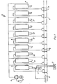
- the total chain lubrication designated 1 can be gem. 1 via a multi-way valve 2, whereupon an actuating device 3 (cf. FIG. 2) triggers the oil supply depending on the speed of the continuously rotating chain 4 via the drive sprocket 5.
- a hydraulic motor 6 then delivers lubricating oil from an oil tank 7 to the individual high-pressure pumps 8, which can be actuated in succession by a cam and deliver the desired amount of lubricant to the lubrication points of the chain 4 by means of the oil application nozzles 9, as will be explained in more detail below.
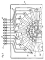
- the spray stroke is synchronized via the chain 4 to be lubricated or its chain wheel 5, which is connected to the chain lubrication 1 via toothed belts (not shown) and an angular gear 12.
- the angular gear 12 has a shaft journal 13 on the output side with a wedged coupling half 14 which engages in the second coupling half 15 carried by the express coupling shaft 17.
- the two coupling halves 14, 15 form a claw coupling 16.
- Two wedges 18 secure on a coupling shaft 17 a cam carrier guide sleeve 19 which receives two control cams 23 which are adjustably mounted in it by means of bolts 22.
- a bearing 24 fixes and includes the guide sleeve 19, which in turn is located in a bearing flange 25, which is connected to the angular gear 12 via a centering plate 26, spacers 27, 28, a pump support plate 29 and a base plate 32.
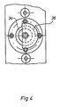
- a bearing 33 carries a driving sleeve 34 with a groove-like recess 35 into which the actuating device 3 engages by means of a driving bracket 36 (see FIG. 4) and the coupling shaft 17 for starting up the lubrication with the Shaft journal 13 connects or separates from it during the lubrication breaks.
- the drive cams 23 meet the run-up slopes 42 and convert the rotary movement into a linear movement for the pump pistons 43, so that each pump piston 43 moves in the direction of the pump head 44 and that in Pressure chamber 45 contains oil via the pipes 46 to the oil application nozzles 9.
- a nozzle holder 47 arranged in the lubrication area above the chain 4 secures the position of the pipes 46, which merge below the nozzle holder 47 into an oil distributor pipe 48 each with a halved pipe cross section, at the ends of which the oil application nozzles 9 are located.
- the nozzles 9 are aligned on the left and right of the chain exactly over the lubrication points 49 on a chain pin 52.
- An additional chain guide 53 supports the precise alignment of the chain 4 under the nozzles 9, just as the oil distributor pipes 9 can also be encapsulated by means of a protective plate 54.
- Each pump 8 has a spring-loaded check valve 57 and 58 in both the suction line 55 and the high-pressure line 56.
- the suction lines 55 receive oil from an oil distributor 62 via feed lines 59.
- the complete lubrication device 1, in particular its mechanically stressed parts, are together with the Oil distributor 62 housed in a housing 63 filled with oil.
- a sensor 64 queries the lubrication points 49 running via the chain wheel 5, which are forwarded to the pause counter 65 as counting pulses during the lubrication breaks. After counting down the number of lubrication points entered into the pause counter 65 to zero, the pause counter 65 releases the pulses for a lubrication counter 66 and at the same time puts the actuating device 3 into operation.
- the actuating device 3 connects the clutch shaft 17 to the shaft journal 13 of the angular gear 12, whereupon the torque removed from the drive sprocket 5 is immediately transmitted to the clutch shaft 17 and rotates together with the cam carrier guide sleeve 19 and the control cams 23 at the same speed as the chain.
- the control cams 23 successively meet the deflection cams 37, which in their starting position rest against the guide ring 39 with a collar 67 and thus consequently all take up the work cycle from the same position into which they also have a return spring 68 after the spray stroke has ended resets.
- the width and slope of the deflection cam 37 precisely defines the start and end of spraying, the control cam 23 moving the pump piston 43 toward the right in the direction of the pump head 44 while running on the run-up slope 42 and thereby the lubricating oil from the pressure chamber 45 to the Nozzles 9 promotes.
- the check valve 58 closes the high-pressure side 56 and prevents the lubricating oil from flowing in again.
- the return spring 68 returns the deflection cam 37 to its initial position, and the check valve 57 of the intake line 55 opens due to the resulting negative pressure, so that the pressure space 45 can be filled via the supply line 59 from the oil distributor 62 at the same time.
- the chain is lubricated by means of the cam control until the lubrication counter 66 has reached zero.
- the actuator 3 then disconnects the chain lubrication release mechanism, i.e. the actuating device 3 is acted upon and separates the coupling shaft from the shaft journal 13 by means of the driving bracket 36 which is latched into the recess 35 of the driving sleeve 34, so that the lubricating device is at rest.
- the trigger mechanism is out of operation (cf. FIG. 5)
- the hydraulic motor or the hydraulic pump 6 also no longer delivers lubricating oil.
- the lubrication cycle only starts again when the pause counter 65 has been counted down to zero and then releases the pulse again for the lubrication counter 66.
Abstract
Description
Die Erfindung betrifft eine Vorrichtung zum schußweisen Aufbringen von flüssigem Schmiermittel auf eine über ein Antriebsrad geführte, schnellaufende Kette mit zumindest einer gegen die Kette gerichteten Schmiermittel-Austrittsdüse, der mittels zumindest einer nockenbetätigten Schmiermittelkolbenpumpe Schmiermittel zugeführt wird, wobei jeder Schmiermittel-Abgabestelle je eine feststehende Schmiermittelkolbenpumpe zugeordnet ist, mit einem oder mehreren Ansteuernocken, die von einer gemeinsamen, axial beweglichen und mit einer Antriebswelle kuppelbaren Kupplungswelle getragen werden und einem Sensor, der ein das An-und Entkuppeln der Welle und Schmieren der Kette bewirkendes Signal abgibt.The invention relates to a device for applying liquid lubricant in shots to a high-speed chain guided by a drive wheel with at least one lubricant outlet nozzle directed against the chain, to which lubricant is supplied by means of at least one cam-actuated lubricant piston pump, each lubricant delivery point having a fixed lubricant piston pump is assigned, with one or more control cams which are carried by a common, axially movable coupling shaft which can be coupled to a drive shaft and a sensor which emits a signal which effects the coupling and uncoupling of the shaft and lubrication of the chain.
Eine Schmiervorrichtung dieser Art ist aus der US-A-4 085 821 bekannt. Das Schmieren einer Kette wird dort durch einen Kontaktarm ausgelöst, der von den Gelenkbolzen der umlaufenden Kette niedergedrückt wird und einen signalauslösenden Schalter betätigt. Durch das Signal wird ein Vorgang zum Einrücken einer Kupplung bewirkt, die eine Motorwelle mit einer Pumpenwelle verbindet. Die Pumpenwelle weist Exzenter auf, von denen beim Drehen der Welle ein jeder einen Kolben gegen die Kraft einer Rückstellfeder in einer Schmiermittelpumpe nach oben bewegt, wobei die in der Pumpe befindliche Schmiermittelmenge über eine Leitung der Schmiermittel-Abgabestelle zugeführt wird. Die Schmiervorrichtung läßt sich allerdings nur für sehr langsam laufende Ketten einsetzen, da sich der die Pumpenwelle antreibende Elektromotor nicht wie erforderlich mit dem Lauf der Kette synchronisieren und auch nicht an sich laufend ändernde Kettengeschwindigkeiten anpassen läßt, so daß ein gezieltes Auftragen einer begrenzten Schmiermittelmenge auf eine bestimmte Schmierstelle nicht möglich ist.A lubricating device of this type is known from US-A-4 085 821. Lubrication of a chain is triggered there by a contact arm, which is pressed down by the hinge pins of the rotating chain and actuates a signal-triggering switch. The signal causes a clutch engagement process that connects a motor shaft to a pump shaft. The pump shaft has eccentrics, each of which moves a piston upward against the force of a return spring in a lubricant pump when the shaft is rotated, the amount of lubricant in the pump being fed via a line to the lubricant delivery point. However, the lubricating device can only be used for very slow-running chains, since the electric motor driving the pump shaft cannot be synchronized with the running of the chain as required and cannot be adapted to continuously changing chain speeds, so that a targeted application of a limited amount of lubricant to one certain lubrication point is not possible.
Außerdem ist durch die EP-A-63 446 eine Vorrichtung zum Schmieren von Ketten bekanntgeworden, bei der die Schmieraggregate samt Tank auf einer drehenden Scheibe bzw. einem drehenden Rad angeordnet sind. Derartige Schmiervorrichtungen sind allerdings zum Schmieren einer großen Anzahl von Schmierstellen mit kleinsten Schmiermittelmengen völlig ungeeignet, denn die Schmieraggregate unterliegen sehr großen Rotationskräften. Das führt insbesondere bei hohen Kettengeschwindigkeiten zu einem unkontrollierten Leerlaufen der Schmierölwege und der Auftragdüsen. Es kann sich deshalb im Zuführsystem zu den Düsen der Schmieraggregate keine druckstabile Ölsäule ausbilden, die aber zwingend erforderlich ist und es erst erlaubt, auf kleinste Hydraulikkolbenhübe in schneller Folge reagieren zu können.In addition, EP-A-63 446 has disclosed a device for lubricating chains, in which the lubricating units and the tank are arranged on a rotating disk or wheel. Such lubrication devices are, however, completely unsuitable for lubricating a large number of lubrication points with the smallest amounts of lubricant, since the lubrication units are subject to very large rotational forces. This leads to an uncontrolled idling of the lubricating oil paths and the application nozzles, especially at high chain speeds. It is therefore not possible for a pressure-stable oil column to form in the feed system to the nozzles of the lubrication units, which is, however, absolutely necessary and only allows one to be able to react to the smallest hydraulic piston strokes in rapid succession.
Der Erfindung liegt die Aufgabe zugrunde, die vorstehenden Nachteile zu vermeiden und eine Schmiervorrichtung zu schaffen, die es insbesondere ermöglicht, bis zu 10 000 Schmierstellen (Kettenbolzen) pro Minute so zu schmieren, daß bei erheblich vermindertem Ölverbrauch die Kettenglieder nur im Bereich des Kettenbolzens zwischen den Laschen an jeder Bolzenseite die gleiche Schmiermittelmenge erhalten, deren geringe Menge sich auch bei hohen Kettengeschwindigkeiten auf eine möglichst große Fläche des Kettenbolzens verteilen läßt.The invention has for its object to avoid the above disadvantages and to provide a lubricating device which in particular makes it possible to lubricate up to 10,000 lubrication points (chain pins) per minute so that with significantly reduced oil consumption, the chain links only in the area of the chain pin between receive the same amount of lubricant on each side of the pin, the small amount of which can be distributed over as large an area of the chain pin as possible even at high chain speeds.
Diese Aufgabe wird erfindungsgemäß dadurch gelöst, daß die Antriebswelle über das vom Ketten-Antriebsrad abgenommene Drehmoment angetrieben und zwangssynchronisiert ist, daß alle Schmiermittelkolbenpumpen um die Antriebswelle herum und in einer Radialebene angeordnet sind, in der auch die Ansteuernocken auf dem Umfang der Antriebswelle positioniert sind, daß jede Schmiermittelkolbenpumpe ein federbelastetes Rückschlagventil in der Ansaug-und Hochdruckleitung aufweist, das in der Ansaugleitung gegen einen Vordruck in dieser Leitung schließt und mit einem eine den Spritzbeginn und das Spritzende an der Schmiermittel-Abgabestelle festlegenden Anlaufschräge aufweisenden Umlenknocken versehen ist, dem wenigstens einer der mit derselben Geschwindigkeit wie die Kettengeschwindigkeit rotierender Ansteuernocken der über die Kupplung der Antriebswelle mit dem Kettenrad der Kette gekuppelten Kupplungswelle im Verlaufe des Drehens gegenüberliegt, daß der dem antreibenden Kettenrad zugeordnete Sensor die Anzahl der über das Kettenrad laufenden Schmiermittel-Abgabestellen feststellt und diese als Zählimpulse an ein die Anzahl der vorhandenen Schmiermittel-Abgabestellen enthaltenes Schmier- bzw. Pausenzählwerk weiterleitet, das nach dem Herunterzählen der eingegebenen Anzahl Schmiermittel-Abgabestellen bis auf Null die Impulse für das Schmierzählwerk freigibt und gleichzeitig das Ankuppeln der Wellen veranlaßt, und daß das Schmierzählwerk nach dem Herunterzählen der eingegebenen Anzahl Schmiermittel-Abgabestellen bis auf Null schließlich das Entkuppeln der Wellen veranlaßt.This object is achieved in that the drive shaft is driven and synchronized by the torque removed from the chain drive wheel and that all lubricant piston pumps are arranged around the drive shaft and in a radial plane in which the control cams are positioned on the circumference of the drive shaft. that each lubricant piston pump has a spring-loaded check valve in the intake and high-pressure line, which closes in the intake line against a pre-pressure in this line and is provided with a deflection cam which defines the start of the spray and the end of the spray at the lubricant dispensing point, at least one of which at the same speed as the chain speed of rotating control cams of the coupling shaft coupled via the coupling of the drive shaft to the chain wheel of the chain in the course of rotation, that the sens assigned to the driving chain wheel or determines the number of lubricant delivery points running over the sprocket and forwards them as counting impulses to a lubrication or pause counter containing the number of existing lubricant delivery points, which after counting down the entered number of lubricant delivery points down to zero the impulses for the Releases the lubricating counter and at the same time causes the shafts to be coupled, and that the lubricating counter finally causes the shafts to be uncoupled after the number of lubricant dispensing points entered has been counted down to zero.
Insbesondere zum Schmieren schnellaufender Ketten läßt sich damit einerseits ein schnelles Auffüllen der Arbeitszylinder der Schmiermittelkolbenpumpen mit einer stets gleichen Schmiermittelmenge erreichen und andererseits die Ölauftragmenge pro Spritzhub bei allen Kettengeschwindigkeiten konstant halten, während sich die Auftragzeit pro Spritzhub gleichmäßig mit der Kettengeschwindigkeit ändert, weil die Nockenbetätigung der Pumpen zeitlich im wesentlichen gleich zur Kettenbewegung abläuft. Damit wird vermieden, daß die ausgespritzte bzw. zugeführte Ölmenge bei langsamer Kettengeschwindigkeit schlagartig auf die Schmierstellen des Bolzens gelangt und dort einen Tropfen bildet. Hingegen verteilt sich die nur geringe verfügbare Ölmenge von 0,007 cm3 Bis 0,014 cm3 pro Spritzhub auf eine große Fläche des Kettenbolzens, was für das Haftvermögen des Öles auf der Kette besonders wichtig ist und sich auch bei hohen Kettengeschwindigkeiten erreichen läßt.In particular for lubricating high-speed chains, this means that the working cylinders of the lubricant piston pumps can be quickly filled with the same amount of lubricant on the one hand, and the oil application rate per spray stroke at all chain speeds, on the other hand, while the application time per spray stroke changes evenly with the chain speed because the cam actuation of the Pumping runs essentially at the same time as the chain movement. This prevents the sprayed or supplied amount of oil suddenly reaching the lubrication points of the bolt at slow chain speed and forming a drop there. In contrast, the only small amount of oil available from 0.007 cm 3 to 0.014 cm 3 per spray stroke is distributed over a large area of the chain pin, which is particularly important for the oil's adhesion to the chain and can also be achieved at high chain speeds.
Insbesondere das Rückschlagventil in der Hochdruckleitung verschließt sofort nach dem Arbeitstakt des Pumpenkolbens die Hochdruckseite, was ein Nachströmen des Schmieröls sicher verhindert. Beim Rückhub des Pumpenkolbens durch die Rückholfeder entsteht mit dem Verschließen der Hochdruckseite gleichzeitig ein Unterdruck, der das Rückschlagventil in der Ansaugleitung öffnet, wodurch sich der Zylinderraum wieder mit Schmieröl füllt.In particular, the check valve in the high-pressure line closes the high-pressure side immediately after the working stroke of the pump piston, which reliably prevents the lubricating oil from flowing in. During the return stroke of the pump piston by the return spring, when the high-pressure side is closed, a negative pressure is simultaneously created, which opens the check valve in the intake line, causing the cylinder space to be filled with lubricating oil again.
Mittels des Sensors und des Schmier- bzw. Pausenzählwerks läßt sich ein automatischer Betrieb der Kettenschmierung erreichen, bei dem das Schmierzählwerk das Ent- und das Pausenzählwerk das Ankuppeln der Antriebswelle mit der Kupplungswelle veranlaßt.Automatic operation of the chain lubrication can be achieved by means of the sensor and the lubrication or pause counter, in which the lubrication counter causes the uncoupling and the pause counter to couple the drive shaft to the coupling shaft.
Um sicherzustellen, daß alle Schmierstellen der Kette Öl erhalten, was allerdings je Umlauf nur einmal geschehen soll, erhalten die beiden Zählwerke über den Sensor die Impulse und damit die genaue Anzahl der vorbeifahrenden Schmierstellen. Der Schmierstellenzähler enthält die Anzahl der während eines Schmierzyklus zu schmierenden Schmierstellen, und der Pausenzähler enthält die Anzahl der während einer Pause nicht zu zählenden Schmierstellen. Die Zähler sind so geschaltet, daß beim Runterzählen des Schmierstellenzählers vom eingegebenen Wert bis auf Null der Pausenzähler keine Impulse erhält. Bei Erreichen von Null kuppelt die Betätigungsvorrichtung die Kettenschmierung aus, und die Impulse des Sensors gelangen nun auf den Pausenzähler, der von seinem eingestellten Wert nun ebenfalls bis auf Null heruntergezählt wird. Danach beginnt der Zyklus wieder von Neuem. Auf diese Weise arbeitet die Kettenschmierung nicht zeitabhängig, sondern gesteuert von den effektiven Umläufen der zu schmierenden Kette.In order to ensure that all lubrication points in the chain receive oil, which, however, should only happen once per cycle, the two counters receive the pulses via the sensor and thus the exact number of lubrication points passing by. The lubrication point counter contains the number of lubrication points to be lubricated during a lubrication cycle, and the pause counter contains the number of lubrication points not to be counted during a break. The counters are switched so that when the lubrication point counter counts down from the entered value to zero, the pause counter receives no pulses. When zero is reached, the actuating device disengages the chain lubrication, and the sensor pulses now reach the pause counter, which is now also counted down to zero from its set value. Then the cycle starts again. In this way, the chain lubrication does not work time-dependent, but controlled by the effective revolutions of the chain to be lubricated.
Vorzugsweise weist die Schmiervorrichtung zehn auf einem Halbkreis mit Abstand nebeneinanderliegende Schmiermittelkolbenpumpen mit je einem eine Anlaufschräge aufweisenden Umlenknocken sowie zwei mit derselben Geschwindigkeit wie die Kettengeschwindigkeit rotierende und auf der Kupplungswelle derart befestigte Ansteuernocken auf, daß im Verlaufe des Drehens jeweils der eine Ansteuernocken dem Umlenknocken der ersten und der andere Ansteuernocken dem Umlenknocken der letzten Schmiermittelkolbenpumpe gegenüberliegt.Preferably, the lubricating device has ten lubricant piston pumps lying next to each other on a semicircle at a distance, each with a deflection cam with a starting slope and two control cams rotating at the same speed as the chain speed and fastened on the coupling shaft in such a way that in the course of the rotation, the one control cam detaches the deflection cam of the first and the other control cam is opposite the deflection cam of the last lubricant piston pump.
Es eignen sich beispielsweise auch die folgenden Anordnungen: vier Nocken und fünf Pumpen; ein Nocken und zwanzig Pumpen; zwanzig Nocken und eine Pumpe. Hochdruckschmiermittelkolbenpumpen erlauben sehr hohe Taktfolgen, die aber beispielsweise ab einer Taktrate von 4000 Schmierimpulsen pro Minute einen Schmierölvordruck von 2 bar in den Ansaugleitungen benötigen. Die hohen Taktfolgen führen naturgemäß zu einem erhöhten mechanischen Verschleiß und zu einer minderen Schmierqualität. Durch den Einsatz von zehn nacheinander angesteuerten Hochdruckschmierkolbenpumpen lassen sich leicht 10.000 Schmierimpulse pro Minute mit nur 1.000 Takten pro Minute einer einzelnen Einheit realisieren. Das Hydrauliksystem unterliegt keinerlei Rotationskräften. Die von dem Kettenrad abgenommene Kettengeschwindigkeit wird während der Schmierphase auf den mit der Kupplungswelle befestigten Ansteuernocken übertragen, der beim Auftreffen auf die Anlaufschräge des Umlenknockens einer Schmiermittelpumpe aus der Rotationsbewegung eine lineare Bewegung des Schmierpumpenkolbens erzeugt. Die Breite sowie die Schräge des Umlenknockens legen den Spritzanfang und das Spritzende genau fest, weil nur bei dem vom Ansteuernocken verursachten Bewegen des Pumpenkolbens in Richtung zum Pumpenkopf Schmieröl aus den Ölauftragsdüsen austritt und zu den Schmierstellen gelangt. Die rotierenden Ansteuernocken sorgen für ein Synchronisieren der Hochdruckschmiermittelkolbenpumpen untereinander sowie der zu schmierenden Stellen und ermöglichen darüber hinaus ein Festlegen des Arbeitshubes des Pumpenkolbens und damit der geförderten Ölmenge, da sie sich in ihrer Lage verstellen lassen. Je nachdem, ob der Umlaufdurchmesser der Ansteuernocken vergrößert oder verkleinert wird, ändert sich entsprechend der Kolbenhub und die Ölmenge.The following arrangements are also suitable, for example: four cams and five pumps; a cam and twenty pumps; twenty cams and a pump. High-pressure lubricant piston pumps allow very high cycle sequences, which, however, require a lubricating oil pre-pressure of 2 bar in the intake lines, for example, from a cycle rate of 4000 lubrication pulses per minute. The high cycle sequences naturally lead to increased mechanical wear and lower lubrication quality. By using ten high-pressure lubrication piston pumps that are controlled in succession, 10,000 lubrication pulses per minute can be easily achieved with just 1,000 cycles per minute of a single unit. The hydraulic system is not subject to any rotational forces. The chain speed removed from the chain wheel is transmitted during the lubrication phase to the control cam which is fastened to the clutch shaft and which, when it strikes the start slope of the deflection cam of a lubricant pump, generates a linear movement of the lubrication pump piston from the rotational movement. The width and the slope of the deflection cam precisely define the start and end of spraying because only when the pump piston is caused by the control cam to move towards the pump head does lubricant oil emerge from the oil application nozzles and reach the lubrication points. The rotating control cams synchronize the high-pressure lubricant piston pumps with each other and the points to be lubricated, and also enable the working stroke of the pump piston and thus the amount of oil pumped to be determined, since their position can be adjusted. The piston stroke and the oil quantity change depending on whether the circumferential diameter of the control cams is increased or decreased.
Die Umlenknocken der Schmiermittelpumpen greifen in einen Führungsring ein, der diese zum einen in Rotationsrichtung abstützt und zum anderen den Rückhub der Umlenknocken exakt begrenzt, der durch eine den Pumpenkolben zurückstellende Rückholfeder dann einsetzt, wenn der rotierende Ansteuernocken die Anlaufschräge des Umlenknockens nicht mehr berührt. Unter der Kraft der Rückholfeder legt sich ein Umlenknocken mit seiner Anschlagfläche gegen den Führungsring, woraus eine immer gleiche Ausgangslage und damit eine gleichbleibende Ölauftragsmenge resultiert. Die die Pumpenkolben über die Umlenknocken beaufschlagenden Ansteuernocken befinden sich in einer auf der Kupplungswelle aufgekeilten Führungshülse.The deflection cams of the lubricant pumps engage in a guide ring, which on the one hand supports them in the direction of rotation and on the other hand exactly limits the return stroke of the deflection cams, which is activated by a return spring that resets the pump piston when the rotating control cam no longer touches the start slope of the deflection cam. Under the force of the return spring, a deflection cam lays against the guide ring with its stop surface, which always results in the same starting position and thus a constant oil application quantity. The control cams which act on the pump pistons via the deflection cams are located in a guide sleeve wedged onto the coupling shaft.
Das Kuppeln der Kupplungswelle vorzugsweise mit dem angetriebenen Kettenrad der umlaufenden Gliederkette und damit das Abnehmen und Weiterleiten der Kettengeschwindigkeit an die mit der Kupplungswelle rotierenden Ansteuernocken, erfolgt nach einem Vorschlag der Erfindung durch ein mit dem Kettenrad verbundenes Winkelgetriebe, das ausgangsseitig einer als Wellenzapfen ausgebildete Antriebswelle mit einer aufgekeilten Kupplungshälfte einer zweiteiligen Klauenkupplung trägt, die in die andere, fest mit der Kuppelwelle verbundene ausrückbare zweite Kupplungshälfte eingreift. Die Klauenkupplung ermöglicht das Trennen der im wesentlichen von der Kupplungswelle getragenen Schmieraggregate während der Schmierpausen, so daß die über das Winkelgetriebe mit der Geschwindigkeit des Kettenrades umlaufende Antriebswelle in diesem Fall leerläuft und sich auf die Schmieraggregate während dieser Zeit keine Bewegung mehr überträgt.The coupling of the clutch shaft, preferably with the driven chain wheel of the rotating link chain, and thus the removal and forwarding of the chain speed to the control cams rotating with the clutch shaft, is carried out according to a proposal of the invention by an angular gear connected to the chain wheel, which also has a drive shaft designed as a shaft journal on the output side carries a wedged coupling half of a two-part claw coupling which engages in the other disengageable second coupling half which is firmly connected to the coupling shaft. The claw coupling enables the lubrication units, which are essentially carried by the clutch shaft, to be separated during the lubrication breaks, so that the drive shaft rotating via the angular gear at the speed of the chain wheel idles in this case and no more movement is transmitted to the lubrication units during this time.
Das Ausrücken der Kuppelwelle mit der zweiten Kupplungshälfte kann über eine an dem der Klauenkupplung entgegengesetzten Ende der Kupplungswelle angeordnete Mitnehmerhülse erfolgen, die eine Ausnehmung besitzt, in die ein Mitnehmerbügel einer Betätigungsvorrichtung eingreift. Als Betätigungsvorrichtung eignet sich je nach Ausführung beispielsweise ein Handhebel, ein pneumatischer bzw. hydraulischer Stellzylinder oder auch ein elektrisch ansteuerbarer Hubmagnet.The clutch shaft with the second clutch half can be disengaged via a driver sleeve which is arranged on the end of the clutch shaft which is opposite the claw clutch and has a recess into which a driver bracket of an actuating device engages. Depending on the version, a suitable actuating device is, for example, a hand lever, a pneumatic or hydraulic actuating cylinder or an electrically controllable lifting magnet.
Die Schmiervorrichtung läßt sich durch ein die Kupplungswelle mit der Führungshülse aufnehmendes, zwischen einem Lagerflansch angeordnetes Lager über eine Zentrierplatte, Abstandshalter, eine Pumpenträgerscheibe und eine Grundplatte fest mit dem Winkelgetriebe verbinden.The lubricating device can be firmly connected to the angular gear by means of a bearing, which receives the coupling shaft with the guide sleeve and is arranged between a bearing flange, via a centering plate, spacers, a pump support disk and a base plate.
Von einem Pumpenkopf der einzelnen Schmierpumpen bzw. Hochdruckschmiermittelkolbenpumpen bis zu einem horizontalen Düsenhalter oberhalb der Kette verlaufende Rohrleitungen sind in einer Reihe mit Abstand voneinander in dem Düsenhalter angeordnet und gehen darunter in je ein Ölverteilerrohr mit halbiertem Rohrleitungsquerschnitt und je einer Ölauftragsdüse links und rechts der Kette über. Die durch den Arbeitshub des Pumpenkolbens festgelegte Ölmenge gelangt über den Pumpenkopf einer jeden Hochdruckschmiermittelkolbenpumpe und den davon abgehenden Hydraulikrohren bis zum Ölverteilerrohr. Das Halbieren des Rohrleitungsquerschnittes führt zu einer genauen Ölverteilung für beide Ölauftragsdüsen, die somit beide eine gleiche Ölmenge an die Schmierstellen abgeben.Pipes running from a pump head of the individual lubrication pumps or high-pressure lubricant piston pumps to a horizontal nozzle holder above the chain are arranged in a row at a distance from one another in the nozzle holder and pass underneath each into an oil distributor pipe with a halved pipe cross-section and one oil application nozzle to the left and right of the chain . The amount of oil determined by the working stroke of the pump piston passes through the pump head of each high-pressure lubricant piston pump and the hydraulic pipes going out to the oil distributor pipe. Halving the cross-section of the pipeline leads to a precise oil distribution for both oil application nozzles, which therefore both deliver an equal amount of oil to the lubrication points.
Das gezielte Auftragen des Schmieröles auf die Kettenlaschen der Bolzenabschnitte verbessern Kettenführungen im Bereich der Ölauftragsdüsen, die die Kette zwangsführen. Das optimale Ausnutzen der vorhandenen Ölmenge durch ein genaues Auftragen nur an den zu schmierenden Stellen erlaubt es, die Schmierpausen um ein Vielfaches zu verlängern.The targeted application of the lubricating oil to the link plates of the bolt sections improves chain guides in the area of the oil application nozzles, which force the chain. The optimal use of the existing oil quantity by precise application only at the points to be lubricated allows the lubrication breaks to be extended many times over.
Eine Eigenschmierung und damit eine erhöhte Standzeit der Schmiervorrichtung läßt sich erreichen, wenn ein mit Öl gefülltes Gehäuse die gesamte Schmiervorrichtung, insbesondere deren beweglichen Teile aufnimmt.Self-lubrication and thus an increased service life of the lubrication device can be achieved if a housing filled with oil accommodates the entire lubrication device, in particular its moving parts.
Die Erfindung wird nachfolgend anhand eines in der Zeichnung dargestellten Ausführungsbeispiels des näheren erläutert. In der Zeichnung zeigen:
- Fig.1 ein Blockschema der erfindungs. gemäßen Kettenschmierung;
- Fig. eine Gesamtansicht einer Kettenschmierung, teilweise geschnitten;
- Fig. einen Schnitt durch eine Kettenschmierung gemäß Fig. 2 entlang der Linie II-II;
- Fig.4 einen Schnitt durch eine Kettenschmierung gemäß Fig. 2 entlang der Linie 111-111 sowie
- Fig. 5 ein Blockdiagramm einer automatischen Kettenschmierung.
- Fig.1 is a block diagram of the Invention. appropriate chain lubrication;
- Fig. An overall view of chain lubrication, partially cut;
- Fig. A section through a chain lubrication according to Figure 2 along the line II-II.
- 4 shows a section through a chain lubrication according to FIG. 2 along the line 111-111 and
- Fig. 5 is a block diagram of an automatic chain lubrication.
Die insgesamt mit 1 bezeichnete Kettenschmierung läßt sich gem. Fig. 1 über ein Mehrwegeventil 2 ansteuern, worauf eine Betätigungsvorrichtung 3 (vgl. Fig. 2) abhängig von der Geschwindigkeit der stetig umlaufenden Kette 4 über das Antriebskettenrad 5 die Ölversorgung auslöst. Darauf fördert ein Hydraulikmotor 6 aus einem Ölbehälter 7 Schmieröl zu den einzelnen Hochdruckpumpen 8, die sich nockenbetätigt nacheinander ansteuern lassen und mittels der Ölauftragsdüsen 9 die gewünschte Schmiermittelmenge an die Schmierstellen der Kette 4 abgeben, wie nachfolgend noch näher erläutert werden wird.The total chain lubrication designated 1 can be gem. 1 via a multi-way valve 2, whereupon an actuating device 3 (cf. FIG. 2) triggers the oil supply depending on the speed of the continuously rotating chain 4 via the drive sprocket 5. A hydraulic motor 6 then delivers lubricating oil from an oil tank 7 to the individual high-pressure pumps 8, which can be actuated in succession by a cam and deliver the desired amount of lubricant to the lubrication points of the chain 4 by means of the
Das Synchronisieren des Spritzhubes erfolgt über die zu schmierende Kette 4 bzw. deren Kettenrad 5, das über nicht dargestellte Zahnriemen und ein Winkelgetriebe 12 mit der Kettenschmierung 1 verbunden ist. Das Winkelgetriebe 12 besitzt dazu ausgangsseitig einen Wellenzapfen 13 mit einer aufgekeilten Kupplungshälfte 14, die in die zweite, von der ausdrückbaren Kuppelwelle 17 getragenen Kupplungshälfte 15 eingreift. Die beiden Kupplungshälften 14, 15 bilden eine Klauenkupplung 16.The spray stroke is synchronized via the chain 4 to be lubricated or its chain wheel 5, which is connected to the chain lubrication 1 via toothed belts (not shown) and an angular gear 12. For this purpose, the angular gear 12 has a
Zwei Keile 18 sichern auf einer Kupplungswelle 17 eine Nockenträgerführungshülse 19, die zwei in ihr mittels Bolzen 22 verstellbar gelagerte Ansteuernocken 23 aufnimmt. Ein Lager 24 fixiert und schließt die Führungshülse 19 ein, das sich seinerseits in einem Lagerflansch 25 befindet, der über eine Zentrierplatte 26, Abstandshalter 27, 28, eine Pumpenträgerscheibe 29 sowie eine Grundplatte 32 mit dem Winkelgetriebe 12 verbunden ist.Two
An dem der Klauenkupplung 16 entgegengesetzten Ende der Kupplungswelle 17 trägt ein Lager 33 eine Mitnehmerhülse 34 mit einer nutenartigen Ausnehmung 35, in die die Betätigungsvorrichtung 3 mittels eines Mitnehmerbügels 36 eingreift (vgl. Fig. 4) und die Kuppelwelle 17 zum Inbetriebsetzen der Schmierung mit dem Wellenzapfen 13 verbindet bzw. während der Schmierpausen von diesem trennt.At the end of the
Bei zum Schmieren der umlaufenden Kette 4 eingerasteter Kupplungswelle 16 gelangen die mit der Kupplungswelle 17 über die Führungshülse 19 umlaufenden Ansteuernocken 23 nacheinander in Kontakt mit Umlenknocken 37 der Hochdruckpumpen 8, die auf einem Halbbogen der Pumpenträgerscheibe 29 mit Abstand voneinander festgelegt sind (Fig. 3). Die Umlenknocken 37 greifen in Ausnehmungen eines mittels Bolzen 38 auf der Pumpenträgerscheibe 29 festgelegten Führungsringes 39 ein, aus dem sie mit Anlaufschrägen 42 herausragen. Im Verlaufe des Drehens treffen die Ansteuernocken 23 auf die Anlaufschrägen 42 und setzen die Drehbewegung in eine lineare Bewegung für die Pumpenkolben 43 um, so daß sich ein jeder Pumpenkolben 43 in Richtung zum Pumpenkopf 44 bewegt und das im Druckraum 45 enthaltene Öl über die Rohrleitungen 46 bis zu den Ölauftragsdüsen 9 führt. Ein im Schmierbereich oberhalb der Kette 4 angeordneter Düsenhalter 47 sichert die Lage der Rohrleitungen 46, die unterhalb des Düsenhalters 47 in je ein Ölverteilerrohr 48 mit halbiertem Rohrleitungsquerschnitt übergehen, an deren Enden sich die Ölauftragsdüsen 9 befinden. Die Düsen 9 sind links und rechts der Kette genau über den Schmierstellen 49 auf einen Kettenbolzen 52 ausgerichtet. Eine zusätzliche Kettenführung 53 unterstützt das genaue Ausrichten der Kette 4 unter den Düsen 9, wie sich auch die Ölverteilerrohre 9 mittels eines Schutzbleches 54 einkapseln lassen.When the
Jede Pumpe 8 besitzt sowohl in der Ansaugleitung 55 wie auch in der Hochdruckleitung 56 ein federbelastetes Rückschlagventil 57 bzw. 58. Die Ansaugleitungen 55 erhalten über Vorlaufleitungen 59 Öl von einem Ölverteiler 62. Die komplette Schmiervorrichtung 1, insbesondere deren mechanisch beanspruchten Teile sind zusammen mit dem Ölverteiler 62 in einem mit Öl gefüllten Gehäuse 63 untergebracht.Each
Beim automatischen Betrieb der Kettenschmierung gem. Fig. 5 fragt ein Sensor 64 die über das Kettenrad 5 laufenden Schmierstellen 49 ab, die während der Schmierpausen an das Pausenzählwerk 65 als Zählimpulse weitergeleitet werden. Nach dem Herunterzählen der in das Pausenzählwerk 65 eingegebenen Schmierstellenanzahl bis auf Null, gibt das Pausenzählwerk 65 die Impulse für ein Schmierzählwerk 66 frei und setzt gleichzeitig die Betätigungsvorrichtung 3 in Betrieb.With automatic operation of the chain lubrication according to 5, a
Die Betätigungsvorrichtung 3 verbindet die Kupplungswelle 17 mit dem Wellenzapfen 13 des Winkelgetriebes 12, worauf sich unverzüglich das von dem Antriebskettenrad 5 abgenommene Drehmoment auf die Kupplungswelle 17 überträgt und diese zusammen mit der Nockenträgerführungshülse 19 und den Ansteuernocken 23 mit gleicher Geschwindigkeit wie die Kette rotiert. Im Verlaufe des Drehens treffen die Ansteuernocken 23 nacheinander auf die Umlenknocken 37, die in ihrer Ausgangslage mit einem Bund 67 am Führungsring 39 anliegen und somit folglich alle aus der gleichen Position heraus den Arbeitstakt aufnehmen, in die sie eine Rückholfeder 68 nach Ablauf des Spritzhubes auch wieder zurückstellt.The
Die Breite und Schräge des Umlenknockens 37 legt den Spritzbeginn und das Spritzende genau fest, wobei der Ansteuernocken 23 während des Ablaufens auf der Anlaufschräge 42 den Pumpenkolben 43 nach rechts in Richtung auf den Pumpenkopf 44 zubewegt und dabei das Schmieröl aus dem Druckraum 45 bis zu den Düsen 9 fördert. Sofort nach dem Arbeitstakt des Pumpenkolbens 43 schließt das Rückschlagventil 58 die Hochdruckseite 56 ab und verhindert ein Nachströmen des Schmieröles. Die Rückholfeder 68 stellt den Umlenknocken 37 in seine Ausgangslage zurück, und durch den entstehenden Unterdruck öffnet das Rückschlagventil 57 der Ansaugleitung 55, so daß sich gleichzeitig der Druckraum 45 über die Vorlaufleitung 59 aus dem Ölverteiler 62 auffüllen kann.The width and slope of the
Die Kette wird mittels der Nockenansteuerung solange geschmiert, bis das Schmierzählwerk 66 die Zahl Null erreicht hat. Daraufhin trennt die Betätigungsvorrichtung 3 den Auslösemechanismus für die Kettenschmierung, d.h. die Betätigungsvorrichtung 3 wird beaufschlagt und trennt die Kupplungswelle mittels des in die Ausnehmung 35 der Mitnehmerhülse 34 eingerasteten Mitnehmerbügels 36 von dem Wellenzapfen 13, so daß sich die Schmiervorrichtung in Ruhe befindet. Bei außer Betrieb gesetztem Auslösemechanismus (vgl. Fig. 5) fördert auch der Hydraulikmotor bzw. die Hydropumpe 6 kein Schmieröl mehr. Der Schmierzyklus setzt erst dann wieder ein, wenn das Pausenzählwerk 65 bis auf Null heruntergezählt worden ist und danach den Impuls erneut für das Schmierzählwerk 66 freigibt.The chain is lubricated by means of the cam control until the lubrication counter 66 has reached zero. The
Claims (12)
Priority Applications (1)
| Application Number | Priority Date | Filing Date | Title |
|---|---|---|---|
| AT84111889T ATE45129T1 (en) | 1983-11-18 | 1984-10-04 | DEVICE FOR LUBRICATION OF A CHAIN. |
Applications Claiming Priority (2)
| Application Number | Priority Date | Filing Date | Title |
|---|---|---|---|
| DE3341658 | 1983-11-18 | ||
| DE3341658A DE3341658C2 (en) | 1983-11-18 | 1983-11-18 | Device for lubricating a chain |
Publications (3)
| Publication Number | Publication Date |
|---|---|
| EP0142687A2 EP0142687A2 (en) | 1985-05-29 |
| EP0142687A3 EP0142687A3 (en) | 1986-05-14 |
| EP0142687B1 true EP0142687B1 (en) | 1989-08-02 |
Family
ID=6214608
Family Applications (1)
| Application Number | Title | Priority Date | Filing Date |
|---|---|---|---|
| EP84111889A Expired EP0142687B1 (en) | 1983-11-18 | 1984-10-04 | Device for lubricating a chain |
Country Status (8)
| Country | Link |
|---|---|
| US (1) | US4679659A (en) |
| EP (1) | EP0142687B1 (en) |
| JP (1) | JPS60125498A (en) |
| AT (1) | ATE45129T1 (en) |
| AU (1) | AU3517384A (en) |
| CA (1) | CA1240276A (en) |
| DE (1) | DE3341658C2 (en) |
| ZA (1) | ZA848959B (en) |
Families Citing this family (18)
| Publication number | Priority date | Publication date | Assignee | Title |
|---|---|---|---|---|
| US5186280A (en) * | 1991-05-03 | 1993-02-16 | Mattcheck Donald L | High temperature oven conveyor chain lubrication system |
| US5129481A (en) * | 1992-01-29 | 1992-07-14 | Pure-Chem Products Company, Inc. | Apparatus and method for lubricating conveyors |
| US5289899A (en) * | 1992-12-21 | 1994-03-01 | Pure-Chem Products Company, Inc. | Apparatus and method for lubricating conveyors |
| DE4406099C2 (en) * | 1994-02-25 | 2001-07-05 | Bielomatik Leuze & Co | Lubrication device for supplying mobile lubrication points |
| DE19503861C2 (en) * | 1995-02-07 | 1999-07-22 | Satzinger Gmbh & Co | Method for the metered lubrication of a chain drive, in particular a motorcycle chain drive |
| DE19529368C1 (en) * | 1995-08-10 | 1996-10-31 | Dolmar Gmbh | Fuel injection and lubricant feed system for combustion engine |
| JP3208325B2 (en) * | 1996-06-18 | 2001-09-10 | 株式会社育良精機製作所 | Bar feeder |
| DE19739525A1 (en) * | 1997-09-09 | 1999-09-30 | Heinrich Abbrederis | The device T.C. cleaning head enables the cleaning, lubrication and preservation of chains in the installed and dismantled state with minimal space |
| NL1011597C2 (en) * | 1999-03-18 | 2000-09-19 | Haanschoten Josef Gijsbert | Lubricator for drive chain. |
| US7314353B2 (en) * | 2004-10-08 | 2008-01-01 | Urschel Laboratories, Inc. | Pump assembly for transporting a cooling fluid |
| US7489254B2 (en) * | 2005-04-07 | 2009-02-10 | Damian Rodriguez | System and method for monitoring a vertical shaft impact crusher |
| US7455170B2 (en) * | 2005-11-15 | 2008-11-25 | Xact Fluid Solutions Division Of Behnke Lubricants, Jax Usa | Conveyor chain lubrication system |
| DE102006020368A1 (en) * | 2006-02-09 | 2007-08-16 | Cfs Germany Gmbh | Packaging machine with a chain cleaning |
| US20080296093A1 (en) * | 2006-11-24 | 2008-12-04 | Schippers John F | Lubricating Switch |
| MX2007015324A (en) * | 2006-12-18 | 2009-02-20 | Inventio Ag | System and method for lubricating a transport device. |
| EP2966013B1 (en) * | 2014-07-09 | 2019-09-04 | SKF Lubrication Systems France | Telescopic lubrication injector, notably for grease injection system |
| CA2961618C (en) * | 2016-03-22 | 2021-12-21 | Gjr Meyer Service Inc. | Lubrication manifold |
| CN105805523B (en) * | 2016-06-02 | 2018-04-06 | 厦门烟草工业有限责任公司 | Automatic lubrication installation and automatic lubricating method |
Family Cites Families (18)
| Publication number | Priority date | Publication date | Assignee | Title |
|---|---|---|---|---|
| GB592386A (en) * | 1945-05-18 | 1947-09-16 | Tecalemit Ltd | Improvements relating to reciprocating pumps, particularly for central lubrication systems |
| US1900745A (en) * | 1929-12-26 | 1933-03-07 | Sukete Invest Company | Progressive distributing lubricator |
| US1979863A (en) * | 1931-05-19 | 1934-11-06 | Eben H Carruthers | Pump |
| US2022620A (en) * | 1933-06-20 | 1935-11-26 | Texas Co | Lubricating mechanism |
| US2561785A (en) * | 1945-06-15 | 1951-07-24 | Ernest W Davis | Lubricating apparatus |
| DE837793C (en) * | 1950-07-06 | 1952-05-02 | Robert Karl Otto Vogelgesang | Lubricant pump with a plurality of pump elements, each interchangeable for itself and arranged around a common vertical central axis |
| DE1697671U (en) * | 1955-02-21 | 1955-05-05 | Helios App Wetzel & Schlosshau | LUBRICATION TIMER. |
| DE1099282B (en) * | 1956-11-08 | 1961-02-09 | Clarke Chapman Ltd | Lubricating device for link chains |
| US3073415A (en) * | 1960-06-08 | 1963-01-15 | Olsen Mfg Company | Conveyor lubricating apparatus |
| GB1141371A (en) * | 1966-08-12 | 1969-01-29 | Cyril Douglas Lister | Improvements in or relating to spray lubricating devices |
| US3463268A (en) * | 1966-11-14 | 1969-08-26 | Owens Corning Fiberglass Corp | Self-actuated oiling system |
| DE1984854U (en) * | 1967-09-29 | 1968-05-02 | Hans Biel Fa | DEVICE FOR LUBRICATING RUNNING CHAINS. |
| JPS474370Y1 (en) * | 1968-10-11 | 1972-02-15 | ||
| US3561565A (en) * | 1969-09-15 | 1971-02-09 | Dennis Frederick Woor | Pulse-actuated lubrication system |
| US4009764A (en) * | 1974-05-22 | 1977-03-01 | Hafner Henry F | Lubricating apparatus for conveyor chains |
| US4085821A (en) * | 1976-09-07 | 1978-04-25 | Madison-Kipp Corporation | Lubrication system |
| GB2021703B (en) * | 1978-05-25 | 1983-02-09 | Madison Kipp Corp | Electrical lubricating apparatus |
| US4401188A (en) * | 1981-04-06 | 1983-08-30 | C. L. Frost & Son, Inc. | Chain spraying apparatus |
-
1983
- 1983-11-18 DE DE3341658A patent/DE3341658C2/en not_active Expired
-
1984
- 1984-10-04 EP EP84111889A patent/EP0142687B1/en not_active Expired
- 1984-10-04 AT AT84111889T patent/ATE45129T1/en not_active IP Right Cessation
- 1984-11-07 AU AU35173/84A patent/AU3517384A/en not_active Abandoned
- 1984-11-13 CA CA000467626A patent/CA1240276A/en not_active Expired
- 1984-11-16 JP JP59242162A patent/JPS60125498A/en active Pending
- 1984-11-16 ZA ZA848959A patent/ZA848959B/en unknown
-
1986
- 1986-06-18 US US06/875,503 patent/US4679659A/en not_active Expired - Lifetime
Non-Patent Citations (1)
| Title |
|---|
| J. FAISANDIER ET AL: Mécanismes hydrauliques, Paris 1980, Seiten 56-66 * |
Also Published As
| Publication number | Publication date |
|---|---|
| CA1240276A (en) | 1988-08-09 |
| ATE45129T1 (en) | 1989-08-15 |
| US4679659A (en) | 1987-07-14 |
| ZA848959B (en) | 1985-07-31 |
| EP0142687A3 (en) | 1986-05-14 |
| DE3341658C2 (en) | 1986-07-10 |
| JPS60125498A (en) | 1985-07-04 |
| EP0142687A2 (en) | 1985-05-29 |
| DE3341658A1 (en) | 1985-05-30 |
| AU3517384A (en) | 1985-05-23 |
Similar Documents
| Publication | Publication Date | Title |
|---|---|---|
| EP0142687B1 (en) | Device for lubricating a chain | |
| EP1186826B1 (en) | Lubricator for lubricating moving points | |
| EP1656520B1 (en) | Lubricating device and lubricating apparatus containing said device | |
| CH647699A5 (en) | DRIVING DEVICE FOR BENDING SLIDE OF PUNCHING BENDING MACHINES. | |
| EP0502823B1 (en) | Device for intermittent lubrification by a lubricating fog | |
| DE3034284C2 (en) | ||
| DE560073C (en) | Fuel pump | |
| DE3312589C2 (en) | Device for lubricating running chains | |
| DE2514022C3 (en) | Device for lubricating the joints of endless conveyor chains | |
| DE2265037B2 (en) | Device for lubricating the chain of a conveyor, in particular a circular conveyor | |
| DE3430040A1 (en) | Central lubrication system for moving lubrication points | |
| DE947040C (en) | Hydraulically driven piston pump for pumping thick, pulpy masses, e.g. B. Concrete | |
| DE582111C (en) | Dividing device for sausage filling machines | |
| DE475036C (en) | High pressure fuel pump system for direct fuel injection into the cylinders of high-speed engines | |
| DE19834599C2 (en) | Liquid feeding system | |
| DE874697C (en) | Feed device for sewing machines | |
| DE2239692C2 (en) | ||
| CH404326A (en) | Drive device with straight stroke movements that can be changed in length and speed | |
| EP0299326A1 (en) | Turning gear with a hydromechanic overrunning clutch | |
| DE643796C (en) | Device for braking the cigarettes emerging from a straight cigarette machine | |
| EP1538336B1 (en) | Dosing pump | |
| DE493310C (en) | Compound pump with phase-shifted conveyor diagrams, especially for rayon spinning | |
| DE10196445T5 (en) | Liquid pump and dosing device | |
| DE821764C (en) | Piston pump | |
| DE3617396C2 (en) |
Legal Events
| Date | Code | Title | Description |
|---|---|---|---|
| PUAI | Public reference made under article 153(3) epc to a published international application that has entered the european phase |
Free format text: ORIGINAL CODE: 0009012 |
|
| AK | Designated contracting states |
Designated state(s): AT BE CH FR GB IT LI LU NL SE |
|
| PUAL | Search report despatched |
Free format text: ORIGINAL CODE: 0009013 |
|
| AK | Designated contracting states |
Kind code of ref document: A3 Designated state(s): AT BE CH FR GB IT LI LU NL SE |
|
| 17P | Request for examination filed |
Effective date: 19861008 |
|
| 17Q | First examination report despatched |
Effective date: 19870714 |
|
| ITF | It: translation for a ep patent filed |
Owner name: BARZANO' E ZANARDO ROMA S.P.A. |
|
| GRAA | (expected) grant |
Free format text: ORIGINAL CODE: 0009210 |
|
| AK | Designated contracting states |
Kind code of ref document: B1 Designated state(s): AT BE CH FR GB IT LI LU NL SE |
|
| REF | Corresponds to: |
Ref document number: 45129 Country of ref document: AT Date of ref document: 19890815 Kind code of ref document: T |
|
| ET | Fr: translation filed | ||
| GBT | Gb: translation of ep patent filed (gb section 77(6)(a)/1977) | ||
| PLBE | No opposition filed within time limit |
Free format text: ORIGINAL CODE: 0009261 |
|
| STAA | Information on the status of an ep patent application or granted ep patent |
Free format text: STATUS: NO OPPOSITION FILED WITHIN TIME LIMIT |
|
| 26N | No opposition filed | ||
| PGFP | Annual fee paid to national office [announced via postgrant information from national office to epo] |
Ref country code: GB Payment date: 19910919 Year of fee payment: 8 |
|
| PGFP | Annual fee paid to national office [announced via postgrant information from national office to epo] |
Ref country code: FR Payment date: 19911017 Year of fee payment: 8 |
|
| PGFP | Annual fee paid to national office [announced via postgrant information from national office to epo] |
Ref country code: SE Payment date: 19911023 Year of fee payment: 8 |
|
| PGFP | Annual fee paid to national office [announced via postgrant information from national office to epo] |
Ref country code: LU Payment date: 19911025 Year of fee payment: 8 Ref country code: AT Payment date: 19911025 Year of fee payment: 8 |
|
| ITTA | It: last paid annual fee | ||
| PGFP | Annual fee paid to national office [announced via postgrant information from national office to epo] |
Ref country code: NL Payment date: 19911031 Year of fee payment: 8 |
|
| PGFP | Annual fee paid to national office [announced via postgrant information from national office to epo] |
Ref country code: CH Payment date: 19911118 Year of fee payment: 8 |
|
| PGFP | Annual fee paid to national office [announced via postgrant information from national office to epo] |
Ref country code: BE Payment date: 19911127 Year of fee payment: 8 |
|
| EPTA | Lu: last paid annual fee | ||
| PG25 | Lapsed in a contracting state [announced via postgrant information from national office to epo] |
Ref country code: LU Free format text: LAPSE BECAUSE OF NON-PAYMENT OF DUE FEES Effective date: 19921004 Ref country code: GB Effective date: 19921004 Ref country code: AT Effective date: 19921004 |
|
| PG25 | Lapsed in a contracting state [announced via postgrant information from national office to epo] |
Ref country code: SE Effective date: 19921005 |
|
| PG25 | Lapsed in a contracting state [announced via postgrant information from national office to epo] |
Ref country code: LI Effective date: 19921031 Ref country code: CH Effective date: 19921031 Ref country code: BE Effective date: 19921031 |
|
| BERE | Be: lapsed |
Owner name: GERROKAISER DOSENWERK G.M.B.H. & CO. K.G. Effective date: 19921031 |
|
| PG25 | Lapsed in a contracting state [announced via postgrant information from national office to epo] |
Ref country code: NL Effective date: 19930501 |
|
| GBPC | Gb: european patent ceased through non-payment of renewal fee |
Effective date: 19921004 |
|
| NLV4 | Nl: lapsed or anulled due to non-payment of the annual fee | ||
| PG25 | Lapsed in a contracting state [announced via postgrant information from national office to epo] |
Ref country code: FR Effective date: 19930630 |
|
| REG | Reference to a national code |
Ref country code: CH Ref legal event code: PL |
|
| REG | Reference to a national code |
Ref country code: FR Ref legal event code: ST |
|
| EUG | Se: european patent has lapsed |
Ref document number: 84111889.6 Effective date: 19930510 |