EP0142279A2 - Batteriegespeiste Lampeneinheit und ihre Unterstützungscontainer - Google Patents
Batteriegespeiste Lampeneinheit und ihre Unterstützungscontainer Download PDFInfo
- Publication number
- EP0142279A2 EP0142279A2 EP84307035A EP84307035A EP0142279A2 EP 0142279 A2 EP0142279 A2 EP 0142279A2 EP 84307035 A EP84307035 A EP 84307035A EP 84307035 A EP84307035 A EP 84307035A EP 0142279 A2 EP0142279 A2 EP 0142279A2
- Authority
- EP
- European Patent Office
- Prior art keywords
- container
- unit
- flange
- lamp
- battery
- Prior art date
- Legal status (The legal status is an assumption and is not a legal conclusion. Google has not performed a legal analysis and makes no representation as to the accuracy of the status listed.)
- Withdrawn
Links
Images

Classifications
-
- E—FIXED CONSTRUCTIONS
- E01—CONSTRUCTION OF ROADS, RAILWAYS, OR BRIDGES
- E01F—ADDITIONAL WORK, SUCH AS EQUIPPING ROADS OR THE CONSTRUCTION OF PLATFORMS, HELICOPTER LANDING STAGES, SIGNS, SNOW FENCES, OR THE LIKE
- E01F13/00—Arrangements for obstructing or restricting traffic, e.g. gates, barricades ; Preventing passage of vehicles of selected category or dimensions
- E01F13/02—Arrangements for obstructing or restricting traffic, e.g. gates, barricades ; Preventing passage of vehicles of selected category or dimensions free-standing; portable, e.g. for guarding open manholes ; Portable signs or signals specially adapted for fitting to portable barriers
-
- E—FIXED CONSTRUCTIONS
- E01—CONSTRUCTION OF ROADS, RAILWAYS, OR BRIDGES
- E01F—ADDITIONAL WORK, SUCH AS EQUIPPING ROADS OR THE CONSTRUCTION OF PLATFORMS, HELICOPTER LANDING STAGES, SIGNS, SNOW FENCES, OR THE LIKE
- E01F9/00—Arrangement of road signs or traffic signals; Arrangements for enforcing caution
- E01F9/60—Upright bodies, e.g. marker posts or bollards; Supports for road signs
- E01F9/604—Upright bodies, e.g. marker posts or bollards; Supports for road signs specially adapted for particular signalling purposes, e.g. for indicating curves, road works or pedestrian crossings
- E01F9/615—Upright bodies, e.g. marker posts or bollards; Supports for road signs specially adapted for particular signalling purposes, e.g. for indicating curves, road works or pedestrian crossings illuminated
- E01F9/617—Illuminated or wired-up posts, bollards, pillars or like upstanding bodies or structures for traffic guidance, warning or control
-
- E—FIXED CONSTRUCTIONS
- E01—CONSTRUCTION OF ROADS, RAILWAYS, OR BRIDGES
- E01F—ADDITIONAL WORK, SUCH AS EQUIPPING ROADS OR THE CONSTRUCTION OF PLATFORMS, HELICOPTER LANDING STAGES, SIGNS, SNOW FENCES, OR THE LIKE
- E01F9/00—Arrangement of road signs or traffic signals; Arrangements for enforcing caution
- E01F9/60—Upright bodies, e.g. marker posts or bollards; Supports for road signs
- E01F9/688—Free-standing bodies
-
- E—FIXED CONSTRUCTIONS
- E05—LOCKS; KEYS; WINDOW OR DOOR FITTINGS; SAFES
- E05B—LOCKS; ACCESSORIES THEREFOR; HANDCUFFS
- E05B15/00—Other details of locks; Parts for engagement by bolts of fastening devices
- E05B15/14—Tumblers
- E05B15/143—Tumblers elastic, e.g. formed by a spring
-
- E—FIXED CONSTRUCTIONS
- E05—LOCKS; KEYS; WINDOW OR DOOR FITTINGS; SAFES
- E05B—LOCKS; ACCESSORIES THEREFOR; HANDCUFFS
- E05B35/00—Locks for use with special keys or a plurality of keys ; keys therefor
- E05B35/002—Locks for use with special keys or a plurality of keys ; keys therefor for flexible keys
-
- F—MECHANICAL ENGINEERING; LIGHTING; HEATING; WEAPONS; BLASTING
- F21—LIGHTING
- F21V—FUNCTIONAL FEATURES OR DETAILS OF LIGHTING DEVICES OR SYSTEMS THEREOF; STRUCTURAL COMBINATIONS OF LIGHTING DEVICES WITH OTHER ARTICLES, NOT OTHERWISE PROVIDED FOR
- F21V21/00—Supporting, suspending, or attaching arrangements for lighting devices; Hand grips
- F21V21/10—Pendants, arms, or standards; Fixing lighting devices to pendants, arms, or standards
- F21V21/116—Fixing lighting devices to arms or standards
-
- F—MECHANICAL ENGINEERING; LIGHTING; HEATING; WEAPONS; BLASTING
- F21—LIGHTING
- F21W—INDEXING SCHEME ASSOCIATED WITH SUBCLASSES F21K, F21L, F21S and F21V, RELATING TO USES OR APPLICATIONS OF LIGHTING DEVICES OR SYSTEMS
- F21W2111/00—Use or application of lighting devices or systems for signalling, marking or indicating, not provided for in codes F21W2102/00 – F21W2107/00
Definitions
- This invention concerns a battery powered lamp unit in combination with a supporting container.
- a battery powered lamp unit in combination with a supporting container, the combination comprising an integral unit comprising an electric lamp integral with a compartment to contain at least one electric battery to power said lamp and electrical circuit means whereby said lamp can be powered by the battery, a tubular supporting container having an open end into which the integral unit is insertable for support thereby with the container surrounding the compartment and the lamp projecting beyond said open end, locking means comprising engageable elements on the unit and interior of the tubular container such that said elements engage one with another some distance within the container from said open end when the unit is inserted so as to prevent removal of the unit, and said locking means being arranged to be unlocked by key means insertable into the tubular container to cause disengagement of aforesaid engaged elements one from another so that the unit can be removed.
- the locking means automatically locks when the integral unit is inserted a sufficient distance into the container.
- the key means is insertable into the tubular container through an aperture in the container wall.
- the key means may be insertable through the said end of the container in which the unit is inserted.
- the integral unit may comprise
- the unit is insertable into the container battery comnartment first.
- the unit may be arranged to sit on the end of the container when inserted as far as desired thereinto.
- the battery or batteries may be one or more dry cell batteries which may have helical wire terminals as is known per se.
- the locking means may comprise a resiliently biased latch which may be a resilient flange engageable with and disengageable from abutment means.
- the flange may be mounted on the inside of the container wall and the abutment means on the exterior of the battery compartment, or the flange may be on the compartment and the abutment means on the interior of the container.
- the flange may be disposed at an angle transverse to the longitudinal axis of the container and unit so that as the unit is located within the container by a relative movement between the two, the abutment means and flange can one relatively to the other pass with a displacement of the flange by the abutments towards a more axial disposition until the abutment means leaves a free edge of the flange which then springs back to or towards its former attitude so that edge can engage the abutment means and prevent its passing the flange if effort is made to pull the unit from the container.
- the key means acts on the flange to move it from its abutment means obstructing position so the unit can be removed.
- Guide passage means may be defined between the battery compartment and the tubular container to guide the inserted key means from the opening in the container wall to the flange to displace it from the abutment means.
- the key means may be of flexible material, for example plastics, so it may be deformed-after insertion through the aperture so as to move along a direction generally axially of the tubular container towards the locking means by force exerted transversely to the axis of the container on that part of the key means externally of the container.
- the flange may be bifurcated so the free ends of the bifurcations engage respective abutments forming said abutment means.
- a rib aligned with the slot bifurcating the flange may extend along the guide passage means.
- the key means may have a groove extending from its leading end to fit over the rib.
- the leading end of the key means may have a wedge shape, for ease of cooperation with the flange when releasing it from the abutment.
- an unauthorised tool such as a piece of wire is inserted through the opening and along the guide passage means it can only be applied to one bifurcation of the flange leaving the other bifurcation still locking the unit in place.
- an unauthorised tool such as a piece of wire
- the presence of the rib in the guide passage means is particularly effective in serving to frustrate the efforts of thieves since to reach both bifurcations of the flange two unauthorised tools operated in unison are needed one on each side of the rib. This is because the rib prevents a single tool capable of . acting on both bifurcations simultaneously from passing along the guide passage means if the leading end of that tool is not grooved to accommodate the rib.
- the locking means may comprise a plurality of locking arrangements acting to engage within the tubular container and lock the unit therein
- the tubular container can be any desired tube. It may for example be a tubular plastics upright to support horizontal rails of a road traffic or road works barrier, in which case the lamp projects from the top of the post as a warning lamp.
- the unit may include an intermediate part between and integral with the lamp and battery compartment.
- This intermediate part may contain electrical circuits which may comprise control circuits causing the lamp to flash.
- the intermediate part may be outside the tubular container. When that latter is a barrier upright, the unit, and more particularly an outer surface of the intermediate part, may have an exposed coating which is retro-reflective of light.
- the unit, and more particularly the intermediate part may have external means for supporting the barrier rails. That means may be one or more lugs each having a keyhole slot for engagement by means, for example a tether, attached to a said rail.
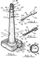
- a tubular supporting container is in the form of an upright post 2 of a barrier to which horizontal rails 4 can be attached by a known tethering technique using headed tethers engaging keyhole slots (only one shown at 6) in a conical part 2A of the post which stands on a base 8.
- That base may be in the form of a container closable by a removable plug or cover 10 so that liquid ballast or particulate or friable solid ballast can be introduced into the container, and the base having a recessed tray-like upper part 12 to receive solid ballast material.
- the post At its upper end the post has a cylindrical part 2B on top of which is a lamp 14 of an integral lamp and battery compartment unit 16.
- the lamp has a light transmissible lens or cover 18 giving illumination over 360° and containing an electric bulb 20 in a bulb holder 22 on an intermediate waisted portion 24 integral or in one piece with the lamp and having a lower surrounding collar 26 engaging on the top of the tube part 2B.
- Intermediate part 24 has a pair of diametrically opposed lugs 28 formed with key-hole slots 6A engageable by headed tethering or attaching means to support upper barrier rails 4A. Between the lugs, the outer surface of part 24 may be coated with material to retro-reflect light incident thereon, for example light from vehicle headlamps.
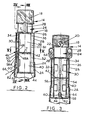
- a dry-cell battery holder 30 of square section having vertical walls 32, 34 and 36 on three sides, the fourth side being open for insertion of batteries B1 and B2 into respective upper and lower compartments 38 and 40 divided from one another by a web 42 which is the base of compartment 38 and the ceiling of the compartment 40 having base web 44.
- the ceiling of compartment 38 is the base of the intermediate part 24. Both ceilings have electrical contacts respectively engaged by helical spring terminals T of the batteries. These contacts (not shown) are incorporated in an electrical circuit (not shown) with which the holder 30 and part 24 are provided to connect the batteries in series and to the lamp bulb.
- This circuit may include within part 24 a circuit arrangement to cause the bulb to flash, and the circuit may include on-off switch means (not shown) for example a pushbutton switch whereby the circuit may be made or interrupted. Access to the switch means to operate the latter may be gained for an operating tool through a hole (not shown) in post 2.
- on-off switch means for example a pushbutton switch whereby the circuit may be made or interrupted. Access to the switch means to operate the latter may be gained for an operating tool through a hole (not shown) in post 2.
- the integral unit 14, 24, 30 which may be substantially a one piece moulding of plastics with additional parts bonded thereto by adhesive, can be locked inside the post 2 by a lock arrangement 46.
- the lock arrangement 46 comprises a resilient metal flange 48 being one leg of metal strip bent into an inverted V-shape having its other leg 50 secured to the inner surface of the tube part 2B.
- Flange 48 is transverse to the axial direction of the post 2 so its free lower end 48A stands further out into the post interior than the upper end of the flange where it joins the leg 50.
- Flange 48 is bifurcated along its length by a central slot 52.
- the lock arrangement 46 further comprises a D air of spaced lugs 54 and 56 on the exterior of the holder 30, integral therewith and transverse to the axial direction of the holder. Each lug is engaged by a respective bifurcation of the flange 48 to hold the unit in the post.
- each lower end may be chamferred as at 62 (Fig. 2).
- An axially extending centre rib 64 between the ribs 58, 60 extends upwardly from adjacent the lower ends to those ribs to some distance above the lugs 54, 56.
- the rib 64 is also integral with the holder 30 and passes between the bifurcations of the flange 48.
- a key 66 shown in Figs. 6 and 7 is used.
- This key of flexible plastics has a handle 68 at one end of a slender shank 70 having a wedge shaped head 72 at the other end.
- the head is bifurcated into two fingers 74 and 76 and the bifurcating slot 78 is extended along the underside of the head and shank by a groove 80.
- hole 82 through the post coincides substantially with the lower ends of two guide passages between ribs 58, 60, 64.
- the key head 74 is inserted into the hole 82 and so the head is between the ribs 58, 60, and the slot 78 and groove 80 accommodate the rib 64.
- the flexible shank 70 bends and allows the key head to be pushed upwardly, from outside the post, along the guide grooves, between the ribs 58, 60, 64 in the slight space between the holder wall 34 and the post until the sloping or cam faces 74A, 76A of the key head respectively press back a said bifurcation of the flange 48 at its free end 48A to release the lugs 54, 56 simultaneously so the unit 16 can be removed. Because the key head is moved in a slight space to its unlocking position it cannot jump out from between the ribs 58, 60.
- Ribs 84 and 86 are of greater depth than the flanges 54 and 56 and serve as guides interacting with parallel axially extending ribs 88 and 90 (Fig. 5) on the interior of the part 2 above the hole 82 ensure the unit 16 is guided accurately during insertion into the post 2 to bring the lugs 54, 56 into position to be locked by the flange 48.
- the lesser depth of the lugs 54, 56 enables them to avoid obstruction by the ribs 88, 90.
- the ribs 88, 90 serve to abut the ribs 84, 86 to prevent rotation of the inserted unit 16 relative to the post 2.
Landscapes
- Engineering & Computer Science (AREA)
- Architecture (AREA)
- Civil Engineering (AREA)
- Structural Engineering (AREA)
- General Engineering & Computer Science (AREA)
- Arrangement Of Elements, Cooling, Sealing, Or The Like Of Lighting Devices (AREA)
Applications Claiming Priority (2)
| Application Number | Priority Date | Filing Date | Title |
|---|---|---|---|
| GB08327642A GB2147986B (en) | 1983-10-14 | 1983-10-14 | Lockable lamp unit and barrier arrangement |
| GB8327642 | 1983-10-14 |
Publications (2)
| Publication Number | Publication Date |
|---|---|
| EP0142279A2 true EP0142279A2 (de) | 1985-05-22 |
| EP0142279A3 EP0142279A3 (de) | 1986-05-14 |
Family
ID=10550257
Family Applications (1)
| Application Number | Title | Priority Date | Filing Date |
|---|---|---|---|
| EP84307035A Withdrawn EP0142279A3 (de) | 1983-10-14 | 1984-10-15 | Batteriegespeiste Lampeneinheit und ihre Unterstützungscontainer |
Country Status (3)
| Country | Link |
|---|---|
| US (1) | US4573109A (de) |
| EP (1) | EP0142279A3 (de) |
| GB (1) | GB2147986B (de) |
Cited By (8)
| Publication number | Priority date | Publication date | Assignee | Title |
|---|---|---|---|---|
| GB2200200A (en) * | 1986-10-21 | 1988-07-27 | Bks Hydraulic Equipment Limite | Securing an object to a structure |
| GB2232477A (en) * | 1986-10-21 | 1990-12-12 | Bks Hydraulic Equipment Limite | A warning lamp unit |
| FR2679288A1 (fr) * | 1991-07-19 | 1993-01-22 | Legrand Sa | Fermeture de porte, notamment pour borne d'hotellerie de plein air. |
| FR2700346A1 (fr) * | 1993-01-14 | 1994-07-13 | Sofrela Sa | Balise routière avertisseuse. |
| WO1994029527A1 (es) * | 1993-06-13 | 1994-12-22 | Segobia Claro Omar Eucaristico | Baliza plegable y transportable, para señalizacion vial, de emergencias en via publica y otros usos |
| GB2300042A (en) * | 1995-04-21 | 1996-10-23 | Celaya Emparanza Galdos Sa | A signalling device |
| WO2000002219A2 (de) * | 1998-07-04 | 2000-01-13 | Werma Signaltechnik Gmbh & Co. | Signalgeber |
| GB2514558A (en) * | 2013-05-28 | 2014-12-03 | Threesixty Blue Ltd | Safety device |
Families Citing this family (24)
| Publication number | Priority date | Publication date | Assignee | Title |
|---|---|---|---|---|
| GB8620615D0 (en) * | 1986-08-26 | 1986-10-01 | Vee Jay Lighting Ltd | Illuminated road barrier |
| GB2197900B (en) * | 1986-11-27 | 1991-05-29 | Policon Limited | Improvements in or relating to road marking apparatus |
| GB8718857D0 (en) * | 1987-08-08 | 1987-09-16 | Glasdon Ltd | Post & rail assembly |
| GB8719505D0 (en) * | 1987-08-18 | 1987-09-23 | Glasdon Ltd | Adaptor for lamp unit |
| GB2255403B (en) * | 1991-05-02 | 1995-01-18 | Jsp Ltd | Improvements relating to lamp holders |
| GB9125735D0 (en) * | 1991-11-30 | 1992-01-29 | Glasdon Ltd | A post and rail assembly |
| US5397197A (en) * | 1993-06-04 | 1995-03-14 | Beavers; Dale W. | Resilient bollard with rotatable collar for alerting vehicles of their location |
| US5597262A (en) * | 1995-03-28 | 1997-01-28 | Dale W. Beavers | Resilient traffic bollard with rotatable collar |
| GB9903985D0 (en) * | 1999-02-23 | 1999-04-14 | Taylor John P | Luminous cone |
| US6305312B1 (en) * | 1999-06-09 | 2001-10-23 | Bent Manufacturing Company | Stackable vertical panel traffic channelizing device |
| US6536369B1 (en) | 2000-08-18 | 2003-03-25 | Bent Manufacturing Company | Handle for traffic delineator |
| US20040159280A1 (en) * | 2003-02-13 | 2004-08-19 | Michael Mohelsky | Pylon |
| US6971329B1 (en) | 2003-03-19 | 2005-12-06 | Robin Hardie Stewart | Lane maker |
| US7270250B2 (en) * | 2004-08-30 | 2007-09-18 | Hygiene-Tecknik Inc. | Disposable dispenser |
| GB0419477D0 (en) * | 2004-09-02 | 2004-10-06 | Advanced Mfg Corp Ltd | Barrier system |
| GB0427782D0 (en) * | 2004-12-18 | 2005-01-19 | Skipper Tm Ltd | Illuminated barrier system,and illumination unit therefor |
| US7538688B1 (en) | 2006-08-23 | 2009-05-26 | Robin Hardie Stewart | Portable area safety zoning system |
| US20080061194A1 (en) * | 2006-09-09 | 2008-03-13 | Edwards William T | Remote control unit stand |
| US20080072815A1 (en) * | 2006-09-23 | 2008-03-27 | Edward Cullin Smith | Traffic Delineator with Signaling Device |
| US20090028639A1 (en) * | 2007-07-27 | 2009-01-29 | Faith Thomas | Apparatus for developing vehicle maneuverability skills |
| US8070380B2 (en) * | 2008-05-12 | 2011-12-06 | Plasticade | Traffic channelizer |
| US20110089390A1 (en) * | 2009-10-16 | 2011-04-21 | Steinkraus Thomas F | Post mount for lighted handrail assembly |
| US8851706B2 (en) | 2012-10-11 | 2014-10-07 | Abdulreidha Abdulrasoul AlSaffar | Lighted road cone |
| US20170002529A1 (en) * | 2014-03-14 | 2017-01-05 | Fsp Holdings Pty Ltd | Roadside barrier |
Citations (12)
| Publication number | Priority date | Publication date | Assignee | Title |
|---|---|---|---|---|
| FR594853A (fr) * | 1925-03-07 | 1925-09-22 | Serrure | |
| US2259610A (en) * | 1940-01-31 | 1941-10-21 | Leland S Dougan | Removable and replaceable traffic marker |
| GB891693A (en) * | 1960-07-05 | 1962-03-14 | Lemelson Jerome H | An illuminated highway marker |
| GB1058161A (en) * | 1963-02-01 | 1967-02-08 | E A Rosengrens Aktiebolag | A burglar resistant lock |
| DE1516604A1 (de) * | 1966-06-02 | 1970-10-01 | Walter Britsch | Transportable Warnleuchte fuer den Strassenverkehr |
| DE2007952A1 (de) * | 1970-02-20 | 1971-09-02 | Weichseibaum, Ernst, 8431 Sulzburg | Leitpfostenvorrichtung |
| DE2438786A1 (de) * | 1974-08-13 | 1976-02-26 | Guenter Weymann | Sicherung fuer baustellenlampen |
| CH579680A5 (en) * | 1974-04-18 | 1976-09-15 | Monney Jean Bernard | Telescopic extending road marker post - is for sites subject to snow and has post retracting into base tube |
| US4083033A (en) * | 1976-05-07 | 1978-04-04 | Royal Industries, Inc. | Traffic control element |
| DE2852831A1 (de) * | 1978-12-07 | 1980-06-19 | Siegfried Guth | Zweiteiliger begrenzungspfahl |
| US4272802A (en) * | 1979-01-23 | 1981-06-09 | Steadman Rufus P | Tower light system |
| GB2107446A (en) * | 1981-10-08 | 1983-04-27 | British Gas Corp | Hazard warning lamp |
Family Cites Families (7)
| Publication number | Priority date | Publication date | Assignee | Title |
|---|---|---|---|---|
| US3920981A (en) * | 1970-03-31 | 1975-11-18 | John J Bailey | Signal lamps |
| DE2132151C3 (de) * | 1971-06-29 | 1975-11-13 | Karl-Heinz 5800 Hagen Gerber | Transportabler Ständer für Absperrvorrichtungen mit Warnleuchte |
| GB1445843A (en) * | 1973-05-03 | 1976-08-11 | North Western Elect Board | Fencing of excavations |
| US3917231A (en) * | 1974-04-01 | 1975-11-04 | Inglis Nurseries Inc | Flexible traffic barrier |
| DE2708982C3 (de) * | 1977-03-02 | 1979-08-23 | Gebola - Baustellenabsperrung- Und Beleuchtungssystem, Gmbh, 7570 Baden- Baden | Transportabler Ständer mit einer elektrischen Warnleuchte |
| GB2102862A (en) * | 1981-05-28 | 1983-02-09 | Cbs Metals Limited | Portable road barriers |
| GB2101180A (en) * | 1981-07-01 | 1983-01-12 | British Gas Corp | Hazard warning barrier |
-
1983
- 1983-10-14 GB GB08327642A patent/GB2147986B/en not_active Expired
-
1984
- 1984-10-15 EP EP84307035A patent/EP0142279A3/de not_active Withdrawn
- 1984-10-15 US US06/661,185 patent/US4573109A/en not_active Expired - Fee Related
Patent Citations (12)
| Publication number | Priority date | Publication date | Assignee | Title |
|---|---|---|---|---|
| FR594853A (fr) * | 1925-03-07 | 1925-09-22 | Serrure | |
| US2259610A (en) * | 1940-01-31 | 1941-10-21 | Leland S Dougan | Removable and replaceable traffic marker |
| GB891693A (en) * | 1960-07-05 | 1962-03-14 | Lemelson Jerome H | An illuminated highway marker |
| GB1058161A (en) * | 1963-02-01 | 1967-02-08 | E A Rosengrens Aktiebolag | A burglar resistant lock |
| DE1516604A1 (de) * | 1966-06-02 | 1970-10-01 | Walter Britsch | Transportable Warnleuchte fuer den Strassenverkehr |
| DE2007952A1 (de) * | 1970-02-20 | 1971-09-02 | Weichseibaum, Ernst, 8431 Sulzburg | Leitpfostenvorrichtung |
| CH579680A5 (en) * | 1974-04-18 | 1976-09-15 | Monney Jean Bernard | Telescopic extending road marker post - is for sites subject to snow and has post retracting into base tube |
| DE2438786A1 (de) * | 1974-08-13 | 1976-02-26 | Guenter Weymann | Sicherung fuer baustellenlampen |
| US4083033A (en) * | 1976-05-07 | 1978-04-04 | Royal Industries, Inc. | Traffic control element |
| DE2852831A1 (de) * | 1978-12-07 | 1980-06-19 | Siegfried Guth | Zweiteiliger begrenzungspfahl |
| US4272802A (en) * | 1979-01-23 | 1981-06-09 | Steadman Rufus P | Tower light system |
| GB2107446A (en) * | 1981-10-08 | 1983-04-27 | British Gas Corp | Hazard warning lamp |
Cited By (13)
| Publication number | Priority date | Publication date | Assignee | Title |
|---|---|---|---|---|
| GB2200200A (en) * | 1986-10-21 | 1988-07-27 | Bks Hydraulic Equipment Limite | Securing an object to a structure |
| GB2232477A (en) * | 1986-10-21 | 1990-12-12 | Bks Hydraulic Equipment Limite | A warning lamp unit |
| GB2200200B (en) * | 1986-10-21 | 1991-04-03 | Bks Hydraulic Equipment Limite | Securing an object to a structure |
| GB2232477B (en) * | 1986-10-21 | 1991-06-26 | Bks Hydraulic Equipment Limite | A warning lamp unit |
| FR2679288A1 (fr) * | 1991-07-19 | 1993-01-22 | Legrand Sa | Fermeture de porte, notamment pour borne d'hotellerie de plein air. |
| FR2700346A1 (fr) * | 1993-01-14 | 1994-07-13 | Sofrela Sa | Balise routière avertisseuse. |
| WO1994029527A1 (es) * | 1993-06-13 | 1994-12-22 | Segobia Claro Omar Eucaristico | Baliza plegable y transportable, para señalizacion vial, de emergencias en via publica y otros usos |
| GB2300042A (en) * | 1995-04-21 | 1996-10-23 | Celaya Emparanza Galdos Sa | A signalling device |
| GB2300042B (en) * | 1995-04-21 | 1998-09-09 | Celaya Emparanza Galdos Sa | Lighted warning apparatus |
| WO2000002219A2 (de) * | 1998-07-04 | 2000-01-13 | Werma Signaltechnik Gmbh & Co. | Signalgeber |
| WO2000002219A3 (de) * | 1998-07-04 | 2001-07-05 | Werma Signaltechnik Gmbh & Co | Signalgeber |
| US6561719B1 (en) | 1998-07-04 | 2003-05-13 | Werma Signaltechnik Gmbh & Co. | Signal transmitter |
| GB2514558A (en) * | 2013-05-28 | 2014-12-03 | Threesixty Blue Ltd | Safety device |
Also Published As
| Publication number | Publication date |
|---|---|
| GB8327642D0 (en) | 1983-11-16 |
| GB2147986A (en) | 1985-05-22 |
| EP0142279A3 (de) | 1986-05-14 |
| GB2147986B (en) | 1987-05-28 |
| US4573109A (en) | 1986-02-25 |
Similar Documents
| Publication | Publication Date | Title |
|---|---|---|
| US4573109A (en) | Battery powered lamp unit and supporting container | |
| ES2745089T3 (es) | Sistema de cierre para un contenedor de almacenamiento | |
| US4231625A (en) | Tape storage cabinet | |
| WO2000008717A1 (en) | Locking electrical outlet | |
| ES2081022T3 (es) | Retretes para uso en vehiculos recreativos. | |
| US4915336A (en) | Adaptor and supporting container primarily for a lamp unit | |
| EP0235103A2 (de) | System zum Befördern von wertvollen Dokumenten | |
| EP0303414B1 (de) | Ständer und Holm-Verbindung | |
| US20040069520A1 (en) | Device for fixing distribution boxes | |
| ES2211680T3 (es) | Conector electrico para la conexion de conductores electricos a un aparato electrico. | |
| GB2125084A (en) | A security upright | |
| JPS6246735A (ja) | 小形電子機器の着脱装置 | |
| ES2248863T3 (es) | Dispositivo lector de tarjetas. | |
| ES2217375T3 (es) | Caja de mando a distancia con modulo accionable por boton pulsador. | |
| ES2217483T3 (es) | Dispositivo antirrobo para automoviles. | |
| CN209862502U (zh) | 磁性锁扣和包括该磁性锁扣的防走失牵引绳 | |
| EP0130020A1 (de) | Mit einem Schlüssel zu betätigende Schliesseinrichtung | |
| JP3940231B2 (ja) | 曲面ドアトイレのドア非常開放装置 | |
| KR200239148Y1 (ko) | 주차 관리기. | |
| KR0133547Y1 (ko) | 차량의 전구 보관함 | |
| KR940000671Y1 (ko) | 교체식 종합공구 | |
| JPH0636615Y2 (ja) | 着脱型電気装置のロック機構 | |
| IT202200001985U1 (it) | Dispositivo e relativo apparato di illuminazione portatile | |
| JPH0635085Y2 (ja) | カード読取装置 | |
| WO2023021486A1 (es) | Sistema de seguridad para pozos y alcantarillas |
Legal Events
| Date | Code | Title | Description |
|---|---|---|---|
| PUAI | Public reference made under article 153(3) epc to a published international application that has entered the european phase |
Free format text: ORIGINAL CODE: 0009012 |
|
| AK | Designated contracting states |
Designated state(s): BE DE FR GB NL |
|
| PUAL | Search report despatched |
Free format text: ORIGINAL CODE: 0009013 |
|
| RHK1 | Main classification (correction) |
Ipc: F21V 21/10 |
|
| AK | Designated contracting states |
Kind code of ref document: A3 Designated state(s): BE DE FR GB NL |
|
| STAA | Information on the status of an ep patent application or granted ep patent |
Free format text: STATUS: THE APPLICATION IS DEEMED TO BE WITHDRAWN |
|
| 18D | Application deemed to be withdrawn |
Effective date: 19870115 |
|
| RIN1 | Information on inventor provided before grant (corrected) |
Inventor name: LACK, ANDREW JOHN |