EP0142005B1 - Verfahren zum Abtrennen einer Komponente aus einem Gasgemisch - Google Patents
Verfahren zum Abtrennen einer Komponente aus einem Gasgemisch Download PDFInfo
- Publication number
- EP0142005B1 EP0142005B1 EP84111876A EP84111876A EP0142005B1 EP 0142005 B1 EP0142005 B1 EP 0142005B1 EP 84111876 A EP84111876 A EP 84111876A EP 84111876 A EP84111876 A EP 84111876A EP 0142005 B1 EP0142005 B1 EP 0142005B1
- Authority
- EP
- European Patent Office
- Prior art keywords
- gas mixture
- gas
- diffusion
- component
- membranes
- Prior art date
- Legal status (The legal status is an assumption and is not a legal conclusion. Google has not performed a legal analysis and makes no representation as to the accuracy of the status listed.)
- Expired
Links
Images

Classifications
-
- B—PERFORMING OPERATIONS; TRANSPORTING
- B01—PHYSICAL OR CHEMICAL PROCESSES OR APPARATUS IN GENERAL
- B01D—SEPARATION
- B01D53/00—Separation of gases or vapours; Recovering vapours of volatile solvents from gases; Chemical or biological purification of waste gases, e.g. engine exhaust gases, smoke, fumes, flue gases, aerosols
- B01D53/22—Separation of gases or vapours; Recovering vapours of volatile solvents from gases; Chemical or biological purification of waste gases, e.g. engine exhaust gases, smoke, fumes, flue gases, aerosols by diffusion
-
- C—CHEMISTRY; METALLURGY
- C01—INORGANIC CHEMISTRY
- C01B—NON-METALLIC ELEMENTS; COMPOUNDS THEREOF; METALLOIDS OR COMPOUNDS THEREOF NOT COVERED BY SUBCLASS C01C
- C01B3/00—Hydrogen; Gaseous mixtures containing hydrogen; Separation of hydrogen from mixtures containing it; Purification of hydrogen; Reversible storage of hydrogen
- C01B3/50—Separation of hydrogen or hydrogen-containing gases from gaseous mixtures, e.g. purification
- C01B3/501—Separation of hydrogen or hydrogen-containing gases from gaseous mixtures, e.g. purification by diffusion
-
- C—CHEMISTRY; METALLURGY
- C01—INORGANIC CHEMISTRY
- C01B—NON-METALLIC ELEMENTS; COMPOUNDS THEREOF; METALLOIDS OR COMPOUNDS THEREOF NOT COVERED BY SUBCLASS C01C
- C01B2203/00—Integrated processes for the production of hydrogen or synthesis gas
- C01B2203/04—Integrated processes for the production of hydrogen or synthesis gas containing a purification step for the hydrogen or the synthesis gas
- C01B2203/0405—Purification by membrane separation
-
- C—CHEMISTRY; METALLURGY
- C01—INORGANIC CHEMISTRY
- C01B—NON-METALLIC ELEMENTS; COMPOUNDS THEREOF; METALLOIDS OR COMPOUNDS THEREOF NOT COVERED BY SUBCLASS C01C
- C01B2203/00—Integrated processes for the production of hydrogen or synthesis gas
- C01B2203/04—Integrated processes for the production of hydrogen or synthesis gas containing a purification step for the hydrogen or the synthesis gas
- C01B2203/0465—Composition of the impurity
- C01B2203/048—Composition of the impurity the impurity being an organic compound
Definitions
- the invention relates to a method for separating a more easily diffusing component from a gas mixture containing this in addition to at least one more difficult to diffuse component by diffusion using semipermeable membranes.
- Semipermeable membranes are used for the separation of gas mixtures that have components with different diffusion rates.
- a gas mixture which is present under increased pressure, is fed in on one side of the membranes. Due to partial pressure differences, a component of the gas mixture diffuses preferentially through the membranes, whereupon it experiences a pressure loss.
- the heavier diffusing components remain on the non-passage side of the membranes and are removed from the diffusion device separately from the separated component.
- the object of the present invention is therefore to develop a method of the type mentioned at the outset which is distinguished by a high yield of the separated components and by low installation and operating costs.
- This object is achieved in that a gas with a higher diffusion rate than that of the more easily diffusing component of the gas mixture is supplied to the gas mixture on the non-passage side of the membranes.
- the admixing of a gas before the diffusion appears to be disadvantageous, since the partial pressure of the diffusing component is thereby deposited on the non-passage side of the membranes.
- the admixed gas since the admixed gas has a significantly higher diffusion rate than the more easily diffusing component of the gas mixture, the admixed gas immediately reaches the passage side of the membranes, where it dilutes the diffusing gas. This reduces the partial pressure of the diffusing component on the passage side of the membranes. This means that the yield of the more easily diffusing component is increased, since a higher diffusion rate is achieved at a low partial pressure.
- the membrane exchange area can be significantly reduced while the yield remains the same.
- the structural design required to carry out the method is small.
- the procedure according to the invention is economical and enables a high yield.
- water vapor has the advantage that it heats the gas mixture and thus prevents non-diffusing components from condensing out in the diffusion device.
- Water vapor admixture is particularly suitable for a gas mixture with carbon dioxide and methane as essential constituents.
- the more easily diffusing component is separated by at least two-stage diffusion, the non-diffusing portion of the gas mixture being fed from the first diffusion stage to a second diffusion stage.
- the gas mixture is a purge gas of an ammonia synthesis.
- the main components of the purge gas are nitrogen and hydrogen, as well as argon and methane. Due to its higher diffusion rate compared to the other components, the hydrogen is separated during the diffusion.
- the gas mixture contains methane and carbon dioxide as essential components.
- a gage mixture occurs, for example, in tertiary oil production.
- the figure shows a method according to the invention for the recovery of carbon dioxide from a gas mixture 23 which contains approximately 80% CO 2 .
- a gas mixture 23 which contains approximately 80% CO 2 .
- the pressure of the gas mixture is approx. 50 x 10 5 Pa (50 bar)
- the temperature is approx. 300 K. B. in tertiary oil production.
- the gas used to dilute the diffusing gas is not fed directly on the passage side of the diffusion device 28, but is already mixed in with the gas mixture to be separated on the non-passage side, from where it is, however, due to its compared to the components of the Gas mixture gets much higher diffusion rate very quickly on the passage side.
- water vapor 24 pressure approx. 50 ⁇ 10 5 Pa (50 bar)
- temperature approx.
- the amount of steam is about 5 to 25%, preferably 10 to 20% of the amount of gas to be broken down.
- Mixing takes place in a separator 25, in which liquefied constituents are separated from the gas mixture via a line 26.
- the gas mixture 27 which is drawn off via the top of the separator 25 is fed to the diffusion device 28. Its temperature is approximately 371 K.
- the water vapor will preferably diffuse through the membranes 9. Due to the water vapor located on the passage side of the membranes, the partial pressure of the carbon dioxide diffusing through the membranes 9 is released, so that a high yield is achieved.
- the non-diffusing portions of the gas mixture (essentially methane) leave the diffusion device 28 on the non-passage side via line 29, while the diffused carbon dioxide / water vapor mixture is removed via line 30.
- the water vapor causes the gas mixture 27 to be heated, so that the C2 + hydrocarbons do not condense out.
Landscapes
- Chemical & Material Sciences (AREA)
- Engineering & Computer Science (AREA)
- Organic Chemistry (AREA)
- Combustion & Propulsion (AREA)
- Inorganic Chemistry (AREA)
- Analytical Chemistry (AREA)
- General Chemical & Material Sciences (AREA)
- Oil, Petroleum & Natural Gas (AREA)
- Chemical Kinetics & Catalysis (AREA)
- Separation Using Semi-Permeable Membranes (AREA)
- Hydrogen, Water And Hydrids (AREA)
- Carbon And Carbon Compounds (AREA)
Description
- Die Erfindung betrifft ein Verfahren zum Abtrennen einer leichter diffundierenden Komponente aus einem diese neben mindestens einer schwerer diffundierenden Komponente enthaltenden Gasgemisch durch Diffusion mit Hilfe von semipermeablen Membranen.
- Semipermeable Membranen werden zur Zerlegung von Gasgemischen verwendet, die Komponenten mit unterschiedlicher Diffusionsgeschwindigkeit aufweisen. Ein Gasgemisch, das unter erhöhtem Druck vorliegt, wird auf der einen Seite der Membranen zugeführt. Aufgrund von Partialdruckunterschieden diffundiert eine Komponente des Gasgemisches bevorzugt durch die Membranen, wobei sie einen Druckverlust erleidet. Die schwerer diffundierenden Komponenten bleiben auf der Nichtdurchgangsseite der Membranen und werden getrennt von der abgetrennten Komponente aus der Diffusionseinrichtung abgeführt.
- Um eine möglichst hohe Ausbeute an der abgetrennten Komponente zu erhalten, werden eine große Membranfläche sowie ein hoher Druckgradient zwischen der Nichtdurchgangsseite und der Durchgangsseite der Membranen benötigt. Diese Anforderungen erhöhen jedoch die Installations- und Betriebskosten der Anlage.
- Es sind bereits Verfahren bekanntgeworden (FR-A 1 409 739, US-A 1, 496, 757), bei denen ein Gasgemisch in einer Diffusionseinrichtung zerlegt wird, wobei auf der Durchgangsseite der Diffusionseinrichtung ein Spülgas zugeführt wird.
- Die für die Zuführung des Spülgases erforderlichen konstruktiven Veränderungen der Diffusionseinrichtung stellen allerdings einen unerwünschten Mehraufwand dar.
- Der vorliegenden Erfindung liegt daher die Aufgabe zugrunde, ein Verfahren der eingangs genannten Art zu entwickeln, das sich durch eine hohe Ausbeute an der abgetrennten Komponenten sowie durch geringe Installations- und Betriebskosten auszeichnet.
- Diese Aufgabe wird erfindungsgemäß dadurch gelöst, daß auf der Nichtdurchgangsseite der Membranen dem Gasgemisch ein Gas mit einer höheren Diffusionsgeschwindigkeit als die der leichter diffundierenden Komponente des Gasgemisches zugeführt wird.
- Die Zumischung eines Gases vor der Diffusion scheint auf den ersten Blick nachteilig, da dadurch der Partialdruck der diffundierenden Komponente auf der Nichtdurchgangsseite der Membranen abgesetzt wird. Da aber das zugemischte Gas eine wesentlich höhere Diffusionsgeschwindigkeit als die leichter diffundierende Komponente des Gasgemisches besitzt, gelangt das zugemischte Gas unverzüglich auf die Durchgangsseite der Membranen, wo es das diffundierende Gas verdünnt. Damit sinkt der Partialdruck der diffundierenden Komponente auf der Durchgangsseite der Membranen. Dies bedeutet, daß die Ausbeute an der leichter diffundierenden Komponente erhöht wird, da bei niedrigem Partialdruck eine höhere Diffusionsrate erreicht wird. Umgekehrt läßt sich bei gleichbleibender Ausbeute die Membran-Austauschfläche deutlich verringern. Der zur Durchführung des Verfahrens erforderliche konstruktive Aufbau ist gering. Die erfindungsgemäße Verfahrensführung ist wirtschaftlich und ermöglicht eine hohe Ausbeute.
- Es erweist sich als Zweckmäßig, wenn das vor der Diffusion beigemischte Gas Wasserdampf ist.
- Neben dem Verdünnungseffekt bietet der Wasserdampf den Vorteil, daß er das Gasgemisch erhitzt und somit ein Auskondensieren von nicht diffundierenden Komponenten in der Diffusionseinrichtung verhindert. Insbesondere eignet sich die Wasserdampfzumischung bei einem Gasgemisch mit Kohlendioxid und Methan als wesentlichen Bestandteilen.
- Bei einer bevorzugten Weiterbildung des Erfindungsgemäßen Verfahrens erfolgt die Abtrennung der leichter diffundierenden Komponente durch mindestens zweistufige Diffusion, wobei der nicht diffundierende Anteil des Gasgemisches aus der ersten Diffusionsstufe einer zweiten Diffusionsstufe zugeführt wird.
- Bei einer bevorzugten Ausgestaltung des erfindungsgemäßen Verfahrens ist das Gasgemisch ein Purge-Gas einer Ammoniaksynthese.
- Das Purge-Gas enthält als Hauptbestandteile Stickstoff und Wasserstoff, sowie Argon und Methan. Aufgrund seiner größeren Diffusionsgeschwindigkeit gegenüber den anderen Komponenten wird der Wasserstoff bei der Diffusion abgetrennt.
- Bei einer anderen bevorzugten Ausführungsform des erfindungsgemäßen Verfahrens enthält das Gasgemisch Methan und Kohlendioxid als wesentliche Bestandteile. Ein derartiges Gagemisch tritt beispielsweise bei der tertiären Ölgewinnung auf.
- Die Erfindung sowie weitere Einzelheiten der Erfindung werden anhand eines schematisch dargestellten Ausführungsbeispiels näher erläutert.
- Hierbei zeigt die Figur ein Verfahren gemäß der Erfindung zur Rückgewinnung von Kohlendioxid aus einem Gasgemisch 23, das etwa 80 % CO2. 20 % CH4 sowie geringe Mengen an C2+-Kohlenwasserstoffen enthält. Der Druck des Gasgemisches beträgt ca. 50 x 105 Pa (50 bar), die Temperatur ca. 300 K. Ein derartiges Gasgemisch fällt z. B. bei der tertiären Ölgewinnung an. Das zur Verdünnung des diffundierenden Gases eingesetzte Gas wird nicht unmittelbar auf der Durchgangsseite der Diffusionseinrichtung 28 zugeführt, sondern es wird dem zu zerlegenden Gasgemisch bereits auf der Nichtdurchgangsseite zugemischt, von wo aus es allerdings aufgrund seiner im Vergleich zu den Komponenten des Gasgemisches wesentlich höheren Diffusionsgeschwindigkeit sehr rasch auf die Durchgangsseite gelangt. Im vorliegenden Fall wird dem Gasgemisch 23 Wasserdampf 24 (Druck ca. 50 x 105 Pa (50 bar), Temperatur ca. 536 K) zugemischt. Die Dampfmenge beträgt ca. 5 bis 25 %, vorzugsweise 10 bis 20 % der Menge des zu zerlegenden Gases. Die Vermischung erfolgt in einem Abscheider 25, in dem verflüssigte Bestandteile über eine Leitung 26 aus dem Gasgemisch abgetrennt werden. Das über den Kopf des Abscheiders 25 abziehende Gasgemisch 27 wird der Diffusionseinrichtung 28 zugeführt. Seine Temperatur beträgt ca. 371 K.
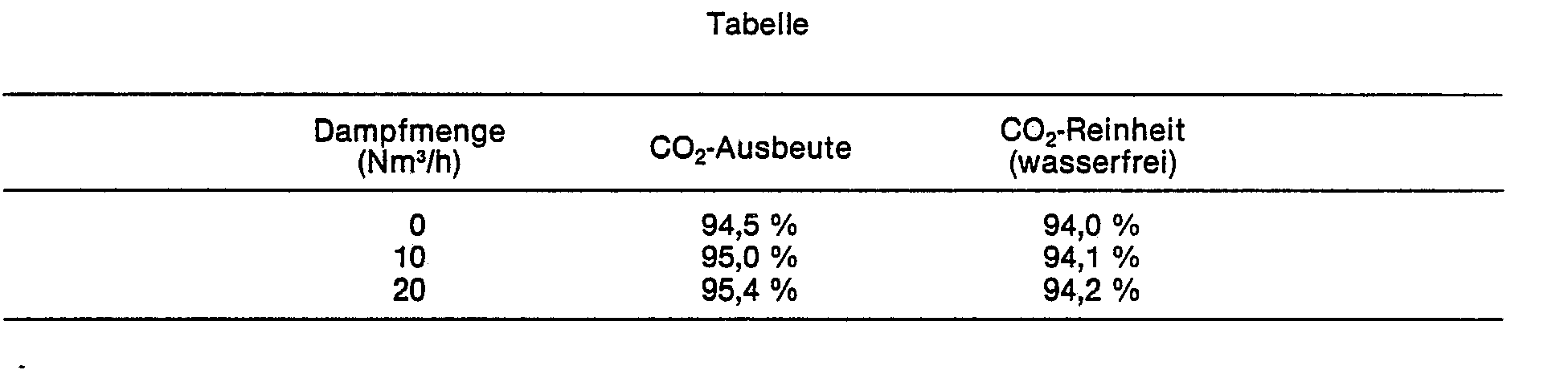
- Da die Permeabilität des Wasserdampfes etwa 20 mal so groß wie die von Kohlendioxid und etwa 500 mal so groß wie die von Methan ist, wird der Wasserdampf bevorzugt durch die Membranen 9 diffundieren. Durch den auf der Durchgangsseite der Membranen befindlichen Wasserdampf wird der Partialdruck des durch die Membranen 9 diffundierenden Kohlendioxids abgesetzt, so daß eine hohe Ausbeute erzielt wird. Die nicht diffundierenden Anteile des Gasgemisches (im wesentlichen Methan) verlassen die Diffusionseinrichtung 28 auf der Nichtdurchgangsseite über Leitung 29, während das diffundierte Kohlendioxid/Wasserdampf-Gemisch über Leitung 30 entnommen wird.
- Neben der Erhöhung der Ausbeute bewirkt der Wasserdampf, daß das Gasgemisch 27 angewärmt wird, so daß ein Auskondensieren der C2+ Kohlenwasserstoffe unterbleibt.
- Die folgende Tabelle zeigt die Ausbeute und Reinheit des Kohlendioxids in Abhängigkeit von der zugeführten Wasserdampfmenge (die Wasserdampfmenge ist in Nm3/h pro 100 Nm3/h Gasgemisch 23 angegeben).
Claims (5)
Priority Applications (1)
| Application Number | Priority Date | Filing Date | Title |
|---|---|---|---|
| AT84111876T ATE34525T1 (de) | 1983-10-15 | 1984-10-04 | Verfahren zum abtrennen einer komponente aus einem gasgemisch. |
Applications Claiming Priority (2)
| Application Number | Priority Date | Filing Date | Title |
|---|---|---|---|
| DE19833337572 DE3337572A1 (de) | 1983-10-15 | 1983-10-15 | Verfahren und vorrichtung zum abtrennen einer komponente aus einem gasgemisch |
| DE3337572 | 1983-10-15 |
Publications (2)
| Publication Number | Publication Date |
|---|---|
| EP0142005A1 EP0142005A1 (de) | 1985-05-22 |
| EP0142005B1 true EP0142005B1 (de) | 1988-05-25 |
Family
ID=6211950
Family Applications (1)
| Application Number | Title | Priority Date | Filing Date |
|---|---|---|---|
| EP84111876A Expired EP0142005B1 (de) | 1983-10-15 | 1984-10-04 | Verfahren zum Abtrennen einer Komponente aus einem Gasgemisch |
Country Status (6)
| Country | Link |
|---|---|
| US (1) | US4591365A (de) |
| EP (1) | EP0142005B1 (de) |
| JP (1) | JPS60137419A (de) |
| AT (1) | ATE34525T1 (de) |
| DE (2) | DE3337572A1 (de) |
| IN (1) | IN163123B (de) |
Families Citing this family (25)
| Publication number | Priority date | Publication date | Assignee | Title |
|---|---|---|---|---|
| US4474586A (en) * | 1983-12-05 | 1984-10-02 | Monsanto Company | Gas separation process |
| US4654063A (en) * | 1984-12-21 | 1987-03-31 | Air Products And Chemicals, Inc. | Process for recovering hydrogen from a multi-component gas stream |
| US4645516A (en) * | 1985-05-24 | 1987-02-24 | Union Carbide Corporation | Enhanced gas separation process |
| EP0442146A1 (de) * | 1985-10-15 | 1991-08-21 | Gerhard Dipl.-Ing. Frey | Verfahren zum Rückgewinnen von Kohlenwasserstoffen |
| US4772295A (en) * | 1986-05-27 | 1988-09-20 | Nippon Kokan Kabushiki Kaisha | Method for recovering hydrocarbon vapor |
| US4834779A (en) * | 1986-10-27 | 1989-05-30 | Liquid Air Corporation | Process for membrane seperation of gas mixtures |
| US4701187A (en) * | 1986-11-03 | 1987-10-20 | Air Products And Chemicals, Inc. | Process for separating components of a gas stream |
| US4841732A (en) * | 1987-12-28 | 1989-06-27 | Sarcia Domenico S | System and apparatus for producing and storing liquid gases |
| DD295741A7 (de) * | 1989-04-05 | 1991-11-14 | Stickstoffwerke Ag Wittenberg,De | Verfahren zur steuerung des methan- und edelgasgehaltes eines ammoniak-wasserstoffrueckgewinnung-edelgas-komplexes |
| US4931070A (en) * | 1989-05-12 | 1990-06-05 | Union Carbide Corporation | Process and system for the production of dry, high purity nitrogen |
| TW314512B (de) * | 1993-09-20 | 1997-09-01 | Shell Int Research | |
| CA2170190A1 (en) * | 1995-03-07 | 1996-09-08 | Dwayne T. Friesen | Volatile organic component removal by membrane separation using countercurrent sweep gas |
| GB9511630D0 (en) * | 1995-06-08 | 1995-08-02 | Cdss Ltd | Gaseous separation by diffusion |
| US5979440A (en) | 1997-06-16 | 1999-11-09 | Sequal Technologies, Inc. | Methods and apparatus to generate liquid ambulatory oxygen from an oxygen concentrator |
| US5851266A (en) * | 1997-06-23 | 1998-12-22 | Praxair Technology,Inc. | Hybrid solid electrolyte ionic conductor systems for purifying inert gases |
| US8475484B2 (en) * | 2000-04-05 | 2013-07-02 | Medrad, Inc. | Liquid seal assembly for a rotating torque tube |
| AR041744A1 (es) * | 2002-10-31 | 2005-05-26 | Alza Corp | Formas de dosificacion que proporcionan la liberacion ascendente de una formulacion liquida |
| US7913497B2 (en) * | 2004-07-01 | 2011-03-29 | Respironics, Inc. | Desiccant cartridge |
| US7213400B2 (en) * | 2004-10-26 | 2007-05-08 | Respironics In-X, Inc. | Liquefying and storing a gas |
| RU170496U1 (ru) * | 2017-02-06 | 2017-04-26 | Федеральное государственное бюджетное учреждение науки Ордена Трудового Красного Знамени Институт нефтехимического синтеза им. А.В. Топчиева Российской академии наук (ИНХС РАН) | Устройство для непрерывного разделения смеси углеводородных газов |
| JP7797193B2 (ja) * | 2021-12-22 | 2026-01-13 | 日本碍子株式会社 | リアクタ及び液体燃料合成方法 |
| JP7245585B1 (ja) * | 2021-12-22 | 2023-03-24 | 日本碍子株式会社 | リアクタ及び液体燃料合成方法 |
| DE102022210662A1 (de) | 2022-10-10 | 2024-04-11 | Hyundai Motor Company | Wasserstofftank und Verfahren zum Betreiben eines Wasserstofftanks |
| AR132237A1 (es) * | 2023-03-30 | 2025-06-04 | Stamicarbon | Acondicionamiento de gas de purga de plantas de nh3 |
| WO2026061886A1 (en) * | 2024-09-18 | 2026-03-26 | Nuovo Pignone Tecnologie - S.R.L. | Hydrogen and nitrogen blending system |
Family Cites Families (13)
| Publication number | Priority date | Publication date | Assignee | Title |
|---|---|---|---|---|
| US1496757A (en) * | 1920-07-26 | 1924-06-03 | Goodyear Tire & Rubber | Process of separating gases |
| US2626679A (en) * | 1949-06-15 | 1953-01-27 | Koppers Co Inc | Diffusion process |
| IT649908A (de) * | 1960-04-01 | |||
| US3251652A (en) * | 1962-05-17 | 1966-05-17 | Engelhard Ind Inc | Process for producing hydrogen |
| DE1252185B (de) * | 1962-08-24 | 1967-10-19 | Engelhard Industries, Inc., Newark, NJ. (V. St. A.) | Verfahren zur Gewinnung von Wasserstoff aus einem wasserstoffhaltigen Gasgemisch |
| FR1409739A (fr) * | 1964-03-13 | 1965-09-03 | Engelhard Ind Inc | Procédé de purification des gaz par diffusion |
| DE1925582C3 (de) * | 1969-05-20 | 1974-07-04 | Linde Ag, 6200 Wiesbaden | Verfahren und Vorrichtung zum Trennen von Stoffgemischen mittels Diffusion |
| US3735558A (en) * | 1971-06-29 | 1973-05-29 | Perma Pure Process Inc | Process for separating fluids and apparatus |
| US4130403A (en) * | 1977-08-03 | 1978-12-19 | Cooley T E | Removal of H2 S and/or CO2 from a light hydrocarbon stream by use of gas permeable membrane |
| US4180552A (en) * | 1978-03-20 | 1979-12-25 | Monsanto Company | Process for hydrogen recovery from ammonia purge gases |
| US4180553A (en) * | 1978-03-20 | 1979-12-25 | Monsanto Company | Process for hydrogen recovery from ammonia purge gases |
| US4172885A (en) * | 1978-03-20 | 1979-10-30 | Monsanto Company | Process for the recovery of hydrogen from ammonia purge gases |
| US4181675A (en) * | 1978-09-19 | 1980-01-01 | Monsanto Company | Process for methanol production |
-
1983
- 1983-10-15 DE DE19833337572 patent/DE3337572A1/de not_active Withdrawn
-
1984
- 1984-10-04 AT AT84111876T patent/ATE34525T1/de not_active IP Right Cessation
- 1984-10-04 EP EP84111876A patent/EP0142005B1/de not_active Expired
- 1984-10-04 DE DE8484111876T patent/DE3471448D1/de not_active Expired
- 1984-10-10 JP JP59212419A patent/JPS60137419A/ja active Pending
- 1984-10-15 US US06/660,814 patent/US4591365A/en not_active Expired - Fee Related
- 1984-10-31 IN IN819/MAS/84A patent/IN163123B/en unknown
Also Published As
| Publication number | Publication date |
|---|---|
| JPS60137419A (ja) | 1985-07-22 |
| EP0142005A1 (de) | 1985-05-22 |
| DE3471448D1 (en) | 1988-06-30 |
| US4591365A (en) | 1986-05-27 |
| ATE34525T1 (de) | 1988-06-15 |
| IN163123B (de) | 1988-08-13 |
| DE3337572A1 (de) | 1985-04-25 |
Similar Documents
| Publication | Publication Date | Title |
|---|---|---|
| EP0142005B1 (de) | Verfahren zum Abtrennen einer Komponente aus einem Gasgemisch | |
| DE69529759T3 (de) | Mehrstufiges trennverfahren mit semipermeablen membranen | |
| DE3856113T2 (de) | Trennung von Wasserstoff enthaltenden Gasgemischen | |
| DE69201942T2 (de) | Verfahren und Vorrichtung zur Herstellung durch Permeation von einem unreinen leichten Gas. | |
| DE69514454T2 (de) | Verfahren und Vorrichtung zur Gastrennung mit Membranen | |
| DE68903812T2 (de) | Verfahren und vorrichtung zur abtrennung eines bestandteils einer gasmischung. | |
| DE3319305C2 (de) | ||
| DE69408388T2 (de) | Verfahren zur Trennung eines Silans mit Hilfe einer Membran | |
| EP4001734A1 (de) | Verfahren zum transportieren von wasserstoff | |
| EP3498668A1 (de) | Verfahren und anlage zur gewinnung von reinhelium | |
| DE69400517T2 (de) | Verfahren zur Erzeugung von Stickstoff mittels halbdurchlässiger Membrane oder Gasabscheiden durch Adsorption | |
| EP0299364A2 (de) | Verfahren und Vorrichtung zur Luftzerlegung durch Rektifikation | |
| EP3954650A1 (de) | Verfahren und anlage zur herstellung von wasserstoff und abscheidung von kohlendioxid | |
| DE69100469T2 (de) | Verfahren und Anlage zur Herstellung eines gasförmigen Bestandteils aus einer gasförmigen Mischung. | |
| DE2521723B2 (de) | Verfahren und Vorrichtung zur Herstellung von reinem Argon durch Fraktionierung der Luft | |
| DE69403090T2 (de) | Entfernung von argon in einem verfahren zur herstellung von ethylenoxid | |
| DE69322207T2 (de) | Verfahren und Vorrichtung zur kombinierten Herstellung von synthetischen Ammoniak und reinem Wasserstoff | |
| DE3521304A1 (de) | Verfahren zur erzeugung eines synthesegases | |
| DE2542705B1 (de) | Verfahren und anlage zur herstellung von mit deuterium angereichertem wasser bei der gewinnung von wasserstoff | |
| DE3617280C2 (de) | Verfahren zur Gewinnung von Kohlenmonoxid | |
| DE60003274T2 (de) | Verfahren und Vorrichtung zur Herstellung von reinem Wasserstoff ausgehend von einem Gas das Helium enthält | |
| DE3444199A1 (de) | Gastrennverfahren | |
| DE2015834A1 (de) | Verfahren zur Extraktion von Deuterium aus Wasserstoffgas in einem bithermischen Verfahren | |
| DE69222032T2 (de) | Verfahren zur kombinierten herstellung von stickstoff und sauerstoff mit regelbarem durchfluss | |
| DE60313149T2 (de) | Verfahren und anlage zur anreicherung mindestens einer komponente eines brennbaren gasgemisches |
Legal Events
| Date | Code | Title | Description |
|---|---|---|---|
| PUAI | Public reference made under article 153(3) epc to a published international application that has entered the european phase |
Free format text: ORIGINAL CODE: 0009012 |
|
| AK | Designated contracting states |
Designated state(s): AT BE DE FR GB IT NL |
|
| 17P | Request for examination filed |
Effective date: 19850529 |
|
| GRAA | (expected) grant |
Free format text: ORIGINAL CODE: 0009210 |
|
| AK | Designated contracting states |
Kind code of ref document: B1 Designated state(s): AT BE DE FR GB IT NL |
|
| PG25 | Lapsed in a contracting state [announced via postgrant information from national office to epo] |
Ref country code: NL Effective date: 19880525 Ref country code: IT Free format text: LAPSE BECAUSE OF FAILURE TO SUBMIT A TRANSLATION OF THE DESCRIPTION OR TO PAY THE FEE WITHIN THE PRESCRIBED TIME-LIMIT;WARNING: LAPSES OF ITALIAN PATENTS WITH EFFECTIVE DATE BEFORE 2007 MAY HAVE OCCURRED AT ANY TIME BEFORE 2007. THE CORRECT EFFECTIVE DATE MAY BE DIFFERENT FROM THE ONE RECORDED. Effective date: 19880525 Ref country code: FR Free format text: THE PATENT HAS BEEN ANNULLED BY A DECISION OF A NATIONAL AUTHORITY Effective date: 19880525 Ref country code: BE Effective date: 19880525 |
|
| REF | Corresponds to: |
Ref document number: 34525 Country of ref document: AT Date of ref document: 19880615 Kind code of ref document: T |
|
| REF | Corresponds to: |
Ref document number: 3471448 Country of ref document: DE Date of ref document: 19880630 |
|
| PG25 | Lapsed in a contracting state [announced via postgrant information from national office to epo] |
Ref country code: AT Effective date: 19881004 |
|
| EN | Fr: translation not filed | ||
| NLV1 | Nl: lapsed or annulled due to failure to fulfill the requirements of art. 29p and 29m of the patents act | ||
| PG25 | Lapsed in a contracting state [announced via postgrant information from national office to epo] |
Ref country code: GB Free format text: LAPSE BECAUSE OF NON-PAYMENT OF DUE FEES Effective date: 19881123 |
|
| GBV | Gb: ep patent (uk) treated as always having been void in accordance with gb section 77(7)/1977 [no translation filed] | ||
| PLBE | No opposition filed within time limit |
Free format text: ORIGINAL CODE: 0009261 |
|
| STAA | Information on the status of an ep patent application or granted ep patent |
Free format text: STATUS: NO OPPOSITION FILED WITHIN TIME LIMIT |
|
| 26N | No opposition filed | ||
| PGFP | Annual fee paid to national office [announced via postgrant information from national office to epo] |
Ref country code: DE Payment date: 19931027 Year of fee payment: 10 |
|
| PG25 | Lapsed in a contracting state [announced via postgrant information from national office to epo] |
Ref country code: DE Effective date: 19950701 |