EP0141902A2 - Device for controlling the closure sequence of double doors - Google Patents
Device for controlling the closure sequence of double doors Download PDFInfo
- Publication number
- EP0141902A2 EP0141902A2 EP84106618A EP84106618A EP0141902A2 EP 0141902 A2 EP0141902 A2 EP 0141902A2 EP 84106618 A EP84106618 A EP 84106618A EP 84106618 A EP84106618 A EP 84106618A EP 0141902 A2 EP0141902 A2 EP 0141902A2
- Authority
- EP
- European Patent Office
- Prior art keywords
- closer
- door
- bowden cable
- leaf
- actuator
- Prior art date
- Legal status (The legal status is an assumption and is not a legal conclusion. Google has not performed a legal analysis and makes no representation as to the accuracy of the status listed.)
- Granted
Links
- 230000001105 regulatory effect Effects 0.000 claims abstract description 6
- 230000000903 blocking effect Effects 0.000 claims description 13
- 238000013016 damping Methods 0.000 claims 1
- 238000009420 retrofitting Methods 0.000 description 8
- 230000008901 benefit Effects 0.000 description 7
- 230000006835 compression Effects 0.000 description 4
- 238000007906 compression Methods 0.000 description 4
- 238000010276 construction Methods 0.000 description 2
- 238000009434 installation Methods 0.000 description 2
- 125000006850 spacer group Chemical group 0.000 description 2
- 230000009471 action Effects 0.000 description 1
- 230000006978 adaptation Effects 0.000 description 1
- 230000004888 barrier function Effects 0.000 description 1
- 238000011109 contamination Methods 0.000 description 1
- 230000008878 coupling Effects 0.000 description 1
- 238000010168 coupling process Methods 0.000 description 1
- 238000005859 coupling reaction Methods 0.000 description 1
- 230000001419 dependent effect Effects 0.000 description 1
- 238000010586 diagram Methods 0.000 description 1
- 238000006073 displacement reaction Methods 0.000 description 1
- 238000010304 firing Methods 0.000 description 1
- 230000001771 impaired effect Effects 0.000 description 1
- 230000014759 maintenance of location Effects 0.000 description 1
- 230000007246 mechanism Effects 0.000 description 1
- 230000000717 retained effect Effects 0.000 description 1
- 230000002441 reversible effect Effects 0.000 description 1
Images


Classifications
-
- E—FIXED CONSTRUCTIONS
- E05—LOCKS; KEYS; WINDOW OR DOOR FITTINGS; SAFES
- E05F—DEVICES FOR MOVING WINGS INTO OPEN OR CLOSED POSITION; CHECKS FOR WINGS; WING FITTINGS NOT OTHERWISE PROVIDED FOR, CONCERNED WITH THE FUNCTIONING OF THE WING
- E05F5/00—Braking devices, e.g. checks; Stops; Buffers
- E05F5/12—Braking devices, e.g. checks; Stops; Buffers specially for preventing the closing of a wing before another wing has been closed
-
- E—FIXED CONSTRUCTIONS
- E05—LOCKS; KEYS; WINDOW OR DOOR FITTINGS; SAFES
- E05Y—INDEXING SCHEME ASSOCIATED WITH SUBCLASSES E05D AND E05F, RELATING TO CONSTRUCTION ELEMENTS, ELECTRIC CONTROL, POWER SUPPLY, POWER SIGNAL OR TRANSMISSION, USER INTERFACES, MOUNTING OR COUPLING, DETAILS, ACCESSORIES, AUXILIARY OPERATIONS NOT OTHERWISE PROVIDED FOR, APPLICATION THEREOF
- E05Y2201/00—Constructional elements; Accessories therefor
- E05Y2201/20—Brakes; Disengaging means; Holders; Stops; Valves; Accessories therefor
- E05Y2201/218—Holders
-
- E—FIXED CONSTRUCTIONS
- E05—LOCKS; KEYS; WINDOW OR DOOR FITTINGS; SAFES
- E05Y—INDEXING SCHEME ASSOCIATED WITH SUBCLASSES E05D AND E05F, RELATING TO CONSTRUCTION ELEMENTS, ELECTRIC CONTROL, POWER SUPPLY, POWER SIGNAL OR TRANSMISSION, USER INTERFACES, MOUNTING OR COUPLING, DETAILS, ACCESSORIES, AUXILIARY OPERATIONS NOT OTHERWISE PROVIDED FOR, APPLICATION THEREOF
- E05Y2201/00—Constructional elements; Accessories therefor
- E05Y2201/20—Brakes; Disengaging means; Holders; Stops; Valves; Accessories therefor
- E05Y2201/23—Actuation thereof
- E05Y2201/232—Actuation thereof by automatically acting means
- E05Y2201/24—Actuation thereof by automatically acting means using lost motion
-
- E—FIXED CONSTRUCTIONS
- E05—LOCKS; KEYS; WINDOW OR DOOR FITTINGS; SAFES
- E05Y—INDEXING SCHEME ASSOCIATED WITH SUBCLASSES E05D AND E05F, RELATING TO CONSTRUCTION ELEMENTS, ELECTRIC CONTROL, POWER SUPPLY, POWER SIGNAL OR TRANSMISSION, USER INTERFACES, MOUNTING OR COUPLING, DETAILS, ACCESSORIES, AUXILIARY OPERATIONS NOT OTHERWISE PROVIDED FOR, APPLICATION THEREOF
- E05Y2201/00—Constructional elements; Accessories therefor
- E05Y2201/60—Suspension or transmission members; Accessories therefor
- E05Y2201/622—Suspension or transmission members elements
- E05Y2201/638—Cams; Ramps
-
- E—FIXED CONSTRUCTIONS
- E05—LOCKS; KEYS; WINDOW OR DOOR FITTINGS; SAFES
- E05Y—INDEXING SCHEME ASSOCIATED WITH SUBCLASSES E05D AND E05F, RELATING TO CONSTRUCTION ELEMENTS, ELECTRIC CONTROL, POWER SUPPLY, POWER SIGNAL OR TRANSMISSION, USER INTERFACES, MOUNTING OR COUPLING, DETAILS, ACCESSORIES, AUXILIARY OPERATIONS NOT OTHERWISE PROVIDED FOR, APPLICATION THEREOF
- E05Y2201/00—Constructional elements; Accessories therefor
- E05Y2201/60—Suspension or transmission members; Accessories therefor
- E05Y2201/622—Suspension or transmission members elements
- E05Y2201/644—Flexible elongated pulling elements
- E05Y2201/654—Cables
-
- E—FIXED CONSTRUCTIONS
- E05—LOCKS; KEYS; WINDOW OR DOOR FITTINGS; SAFES
- E05Y—INDEXING SCHEME ASSOCIATED WITH SUBCLASSES E05D AND E05F, RELATING TO CONSTRUCTION ELEMENTS, ELECTRIC CONTROL, POWER SUPPLY, POWER SIGNAL OR TRANSMISSION, USER INTERFACES, MOUNTING OR COUPLING, DETAILS, ACCESSORIES, AUXILIARY OPERATIONS NOT OTHERWISE PROVIDED FOR, APPLICATION THEREOF
- E05Y2600/00—Mounting or coupling arrangements for elements provided for in this subclass
- E05Y2600/40—Mounting location; Visibility of the elements
- E05Y2600/46—Mounting location; Visibility of the elements in or on the wing
-
- E—FIXED CONSTRUCTIONS
- E05—LOCKS; KEYS; WINDOW OR DOOR FITTINGS; SAFES
- E05Y—INDEXING SCHEME ASSOCIATED WITH SUBCLASSES E05D AND E05F, RELATING TO CONSTRUCTION ELEMENTS, ELECTRIC CONTROL, POWER SUPPLY, POWER SIGNAL OR TRANSMISSION, USER INTERFACES, MOUNTING OR COUPLING, DETAILS, ACCESSORIES, AUXILIARY OPERATIONS NOT OTHERWISE PROVIDED FOR, APPLICATION THEREOF
- E05Y2900/00—Application of doors, windows, wings or fittings thereof
- E05Y2900/10—Application of doors, windows, wings or fittings thereof for buildings or parts thereof
- E05Y2900/13—Type of wing
- E05Y2900/132—Doors
Definitions
- the invention relates to a device for regulating the closing sequence of double-leaf doors with at least one door closer assigned to the active leaf and a control arrangement which can be actuated via the passive leaf and cooperates with the door closer of the active leaf.
- a hydraulic closing sequence controller in which hydraulic door closers assigned to the active leaf and the passive leaf are connected to one another via pressure medium lines, which are in particular laid in the frame, and the flow paths between the pressure medium spaces located on both sides of the locking piston are controlled in such a way that the door closer assigned to the active leaf is only released and the door assigned to it can be moved into the firing position when the door closer assigned to the passive leaf has at least essentially already assumed its closed position.
- the object of the present invention is to design a device of the type defined at the outset using a door closer as a locking device in a particularly simple yet reliable manner, to facilitate assembly and to make the adaptation to the most varied of circumstances problem-free.
- control arrangement consists of an actuator arranged in the area of the passive leaf on the pivot axis side, movable through the ... active leaf between a first and a second switching position and an actuator connected to the actuator, which is up to Door closer of the active leaf extending and mechanically transmitting the actuator movement exists connecting element, and that the active leaf side end of the connecting element engages a control element blocking the closing movement of the door closer in one of the two switching positions of the actuator.
- the connecting element mechanically transmitting the actuator movement is preferably a Bowden cable, but it is also possible, depending on the respective installation conditions, to use a rod rotatably or displaceably mounted in the frame or a combination of rod and Bowden cable as the mechanically transmitting connecting element.
- a Bowden cable is used, this is preferably connected to the door closer via a screw head and the control element assigned to the Bowden cable is biased into the blocking position by means of a spring.
- the closing angle of the passive leaf can be adjusted by adjusting the relative position of the Bowden cable sleeve and Bowden cable on the screw head conveniently and precisely specify when the active leaf is released in the closing direction.
- control element consists of a locking slide arranged in a guide housing, which is under the pretension of a spring and is connected to the Bowden cable and which cooperates with a cam disc which is fixed in a rotationally fixed manner on the closer axis and which acts as a stop for the locking has slide.
- the guide housing can preferably be screwed to the closer housing, i.e. the guide housing can be screwed onto the closer housing without difficulty even in the case of retrofitting.
- a cam disc which is connected in a rotationally fixed manner to the closer arm and has a stop is arranged, which cooperates with a locking slide which is guided in the other arm and is under the pretension of a spring and which engages with it Sleeve connected to the arm supported Bowden cable.
- each closer 2, 2 ' is connected to the frame 13 via a linkage 9.
- an actuator 14 which, when the fixed leaf is in the closed position, assumes a first position and a second position in the open position of the fixed leaf 11.
- These two positions or positions of the actuator 14 are transmitted via a mechanical connecting element, in the example shown by means of a Bowden cable arrangement 5, to the door closer 2 of the active leaf in order to close the active leaf 12 as a function of the position of the actuator 14 and thus as a function of the position to control the passive leaf 11.
- the Bowden cable 5 is guided in the frame 13 and, when the device is mounted, does not appear optically and, in particular, does not cause any problems.
- top door closers according to FIG. 1 can in principle be used in the same way for floor door closers.
- Fig. 2 shows a mechanical embodiment of a device for regulating the closing sequence, wherein a cam 3 is placed on the axis 10 of the closer 2, which by a corresponding flattening of the axis
- the cam disc 3 is held down by a spacer sleeve 6 extending between this disc 3 and a link arm 9 via the screw which serves to fix the linkage.
- a locking mechanism interacts with the cam disc 3, which consists of a locking slide 8 which is displaceably mounted in a guide housing 4 and which is under the prestress of a compression spring 17 and is connected to the Bowden cable 5.
- the guide housing 4 is preferably screwed onto the top of the closer housing 2.
- the locking slide 8 engages on the cam disc 3 and interacts with a cam stop 7, this stop 7 being designed to be sufficiently stable and formally such that the decoupling of the stop 7 and the locking slide 8 can be carried out with comparatively low forces.
- the mutually engaging surfaces of stop 7 and locking slide 8 preferably extend obliquely to the locking slide longitudinal axis.
- the holding angle of the active leaf defined by the position of the stop 7 on the cam 3 must be selected so that the passive leaf can pass the fixed leaf when the active leaf is blocked. This is possible with an opening angle of the active leaf in the range of approximately 20 ° to 40 °, and the angle determined by the position of the stop 7 is also selected in this range.
- Fig. 3 shows a variant with locking device integrated in the closer linkage, which is characterized above all by easy retrofitting, since practically only the linkage 9, 15 has to be replaced for the purpose of retrofitting.
- the cam 3 is rotatably connected to the closer arm 9, which is connected to the axis 10 of the closer 2.
- the locking device assigned to the cam plate 3 is accommodated in the link arm 15, into which the Bowden cable 5 is inserted.
- the link arm is connected to the frame in a pivot bearing pin 16, while the closer 2 is fastened to the active leaf 12.
- FIG. 4 shows the arrangement according to FIG. 3 in the cut and opened state. It can be seen that the sleeve of the Bowden cable 5 at the entry point of the Bowden Switzerlands in the closer arm 15 supported on the closer arm wall and the Bowden cable itself is connected to the locking slide 8, which is slidably guided in a corresponding recess of the arm 15 and is biased in the direction of the cam plate 3 by means of a compression spring 17.
- the advantage in practice is that the Bowden cable 5 fixed to the frame does not form a large loop with the normally open door 2 must be placed, but that this Bowden cable can run directly from the frame into the linkage or the closer arm 15. Since the arm 15 moves relative to the wall less than the closer 2 mounted on the door 12, the Bowden cable 5 is little stressed and its smoothness is not impaired.
- FIG. 5 to 7 show a variant with stepless retention of the active leaf, using a wrap spring 18 which cooperates with a pivot bearing pin 16 connected in a rotationally fixed manner to the link arm 15 in the form of a spring freewheel.
- One end 19 of this spring 18 is connected to the bearing sleeve for the link arm 15 connected to the frame 13, while at the other end 20 of the spring 18 the Bowden cable acts, the sleeve of which is supported in a frame-fixed manner.
- This support 21 can be seen in FIG. 6.
- the principle of operation of this stepless holding device is shown in FIG. 7. If the end 20 of the spring 18 is pulled in the direction of the arrow 22 by means of the Bowden cable 5, the bolt 16 and thus the link arm 15 can rotate or pivot freely. If the Bowden cable 5 is relieved, the pivot bearing pin 16 tightens when rotating in the direction of the arrow 23 in the spring 18 and is held in place via the lower end 19 of the spring 18 which is firmly connected to the bearing bush.
- the closer is mechanically blocked at an opening angle of the active leaf preferably chosen between 20 ° and 40 ° via a blocking member 26, which prevents the movement of the piston 24 in the closer 2.
- the blocking member 26 is under the action of a compression spring 17 which biases the B lockierglied.26 in such a manner that it protrudes in a relaxed Bowden cable 5 in the located left of the piston 24 pressure chamber and forms a barrier for the piston 24th If the Bowden cable 5 is actuated or pulled, this causes the link 26 to be withdrawn from the pressure chamber and the piston 24 can move in the closing direction, which results in the closer being closed.
- the closing speed can be adjusted via a valve 28 which is arranged in a connecting channel 27 between the spaces located on both sides of the piston 24.
- the piston 24 is biased in the usual way in the closing direction by a closing spring 25.
- the embodiment according to FIG. 8 is particularly suitable for applications in which the closer is mounted on the frame 13 and not on the door.
- the Bowden cable 5 can be laid in a particularly simple manner.
- the blocking member 26 can also be actuated via a tappet by a cam disk which is arranged on a rod which is dependent on the movement of the stand wing rotatable, or can be reversed depending on the respective position of the passive leaf between two pivot positions.
- the pivoting of the cam disc then controls the blocking member 26 in a corresponding manner, as has been explained in connection with FIG. 8.
- the movement of the closer piston is controlled depending on the respective position of the actuator assigned to the passive leaf by a valve 29 which is arranged in a flow channel 27, 27 'between the two pressure chambers of the closer and via rigid or flexible Controls between the closed or open position is reversible.
- the valve In the closed position, the valve prevents any loss of oil between the two pressure chambers and thus any movement of the piston.
- the valve 29 is biased into the closed position by a compression spring 17. A movement of the closer piston is not possible. If the valve 29 is actuated via the plunger 30 protruding beyond the closer housing 2, the channel which is initially blocked is opened and the door can run into the closed position.
- the pushing of the plunger 30 against the force of the spring 17 takes place via a cone 31 which is mounted on a rod 32 which can be displaced relative to the closer 2.
- the linear displacement of this rod 32 again takes place as a function of the actuator 14 shown in FIG. 1.
- a further valve 28 is arranged directly adjacent to the valve 29 in the channel 27, which allows the flow resistance in this channel to be changed and thus the closing speed to be regulated.
- valve 29 housed in the closer 2 via a Bowden cable arrangement 5, 5 'is shown in FIG. 10.
- the sleeve 5 of the Bowden cable is supported on an adjusting screw 33 of a screw head 34, which can be screwed into a corresponding threaded hole in the housing 2.
- the adjusting screw 33 can be used to adjust the Bowden cable.
- the valve 29 is biased by the spring 17 into the closed position, in which a passage of oil between the channel sections 27 and 27 'is prevented and thus movement of the closer piston is blocked.
- the valve body is shifted to the left, by a maximum of the stroke limited by a spacer sleeve 35.
- the channel section 27 is connected to the channel section 27 ′, the oil can flow freely through the channel via a downstream regulating valve, and the active leaf can close in a damped manner.
- This variant is characterized by good integrability in a door closer, compactness and easy adjustability.
- the mechanical design variants of the invention are characterized by a particularly simple construction and easy retrofitting, and in these embodiments there is also no so-called creep of the closer due to low leakage of the hydraulics when the closer is determined, i.e. A slow closing of the respective door is reliably prevented
- the training variants with a valve integrated in the closer and the blocking element have the additional advantages that the compact design of the closer housing is retained, no complicated installation on site when the double-leaf door, in particular fire protection door, is required , since the closing sequence controller is already integrated in the closer and that contamination of a control element or control valve is made more difficult by the integrated design, which leads to a maintenance-friendly overall arrangement.
Landscapes
- Power-Operated Mechanisms For Wings (AREA)
- Closing And Opening Devices For Wings, And Checks For Wings (AREA)
- Specific Sealing Or Ventilating Devices For Doors And Windows (AREA)
Abstract
Description
Die Erfindung betrifft eine Vorrichtung zur Regelung der Schließfolge von zweiflügeligen Türen mit zumindest einem dem Gangflügel zugeordneten Türschließer und einer über den Standflügel betätigbaren, mit dem Türschließer des Gangflügels zusammenwirkenden Steueranordnung.The invention relates to a device for regulating the closing sequence of double-leaf doors with at least one door closer assigned to the active leaf and a control arrangement which can be actuated via the passive leaf and cooperates with the door closer of the active leaf.
Vorrichtungen dieser Art sind bekannt. Sie müssen gewähr- leisten, daß die beiden Flügel einer zweiflügeligen Türe aus beliebigen öffnungsstellungen stets so in die Schließlage überführt werden, daß der Standflügel als erster in die Schließposition gelangt und anschließend der Gangflügel in die Schließposition einläuft und damit die Türe ordnungsgemäß und vollständig geschlossen ist.Devices of this type are known. You must ensure that the two leaves of a double-leaf door are always brought into the closed position from any open position so that the passive leaf is the first to reach the closed position and then the active leaf runs into the closed position and the door is closed properly and completely .
Neben mechanischen Schließfolgereglern ist auch bereits ein hydraulischer Schließfolgeregler bekannt, bei dem dem Gangflügel und dem Standflügel zugeordnete hydraulische Türschließer über Druckmittelleitungen, die insbesondere in der Zarge verlegt sind, miteinander verbunden und die Strömungswege zwischen den beiderseits der Schließkolben gelegenen Druckmittelräumenin der Weise gesteuert sind, daß der dem Gangflügel zugeordnete Türschließer erst dann freigegeben wird und die ihm zugeordnete Tür in die Schießlage überführen kann, wenn der dem Standflügel zugeordnete Türschließer zumindest im wesentlichen bereits seine Schließlage eingenommen hat.In addition to mechanical closing sequence controllers, a hydraulic closing sequence controller is also known, in which hydraulic door closers assigned to the active leaf and the passive leaf are connected to one another via pressure medium lines, which are in particular laid in the frame, and the flow paths between the pressure medium spaces located on both sides of the locking piston are controlled in such a way that the door closer assigned to the active leaf is only released and the door assigned to it can be moved into the firing position when the door closer assigned to the passive leaf has at least essentially already assumed its closed position.
Aufgabe der vorliegenden Erfindung ist es, eine Vorrichtung der eingangs definierten Art unter Verwendung eines Türschließers als Feststellvorrichtung in besonders einfacher und dennoch betriebssicherer Art auszugestalten, die Montage zu erleichtern und die Anpassung an die unterschiedlichsten Gegebenheiten problemfrei zu gestalten.The object of the present invention is to design a device of the type defined at the outset using a door closer as a locking device in a particularly simple yet reliable manner, to facilitate assembly and to make the adaptation to the most varied of circumstances problem-free.
Gelöst wird diese Aufgabe nach der Erfindung im wesentlichen dadurch, daß die Steueranordnung aus einem im schwenkachsenseitigen Bereich des Standflügels angeordneten, durch den ... Standflügel zwischen einer ersten und einer zweiten Schalt- stellung bewegbaren Stellglied und einem mit dem Stellglied verbundenen, sich bis zum Türschließer des Gangflügels erstreckenden und die Stellgliedbewegung mechanisch übertragenden Verbindungsorgan besteht, und daß das gangflügelseitige Ende des Verbindungsorgans an einem die Schließbewegung des Türschließers in einer der beiden Schaltstellungen des Stellglieds blockierenden Steuerglied angreift.This object is achieved according to the invention essentially by the fact that the control arrangement consists of an actuator arranged in the area of the passive leaf on the pivot axis side, movable through the ... active leaf between a first and a second switching position and an actuator connected to the actuator, which is up to Door closer of the active leaf extending and mechanically transmitting the actuator movement exists connecting element, and that the active leaf side end of the connecting element engages a control element blocking the closing movement of the door closer in one of the two switching positions of the actuator.
Durch die Verwendung eines die Stellgliedbewegung und damit die Momentanposition des Standflügels mechanisch zumSchließer des Gangflügels übertragenden Verbindungsorgans lassan sich neben den sich aus der Lösung der gestellten Aufgabe ergebenden Vorteilenauch noch die Vorteile erzielen, daß keine Eingriffe in die Hydraulik von Türschließern erforderlich sind und bezüglich bereits montierter Schließer die Möglichkeit der Nachrüstung gegeben ist.Through the use of a connecting element which mechanically transmits the actuator movement and thus the instantaneous position of the passive leaf to the closer of the active leaf, in addition to the advantages resulting from the solution of the task at hand, the advantages can also be achieved that no interventions in the hydraulics of door closers are necessary and with respect to those already installed Closer the possibility of retrofitting is given.
Bevorzugt ist das die Stellgliedbewegung mechanisch übertragende Verbindungsorgan ein Bowdenzug, aber es ist in Abhängigkeit von den jeweiligen Einbaugegebenheiten auch möglich, als mechanisch übertragendes Verbindungsorgan eine in der Zarge dreh- oder verschiebbar gelagerte Stange oder eine Kombination von Stange und Bowdenzug zu verwenden.The connecting element mechanically transmitting the actuator movement is preferably a Bowden cable, but it is also possible, depending on the respective installation conditions, to use a rod rotatably or displaceably mounted in the frame or a combination of rod and Bowden cable as the mechanically transmitting connecting element.
Im Falle der Verwendung eines Bowdenzuges ist dieser vorzugsweise mit dem Türschließer über einen Schraubkopf verbunden und das dem Bowdenzug zugeordnete Steuerglied mittels einer Feder in die Blockierlage vorgespannt. Auf diese Weise läßt sich durch Einstellung der Relativlage von Bowdenzughülse und Bowdenzug am Schraubkopf der Schließwinkel des Standflügels bequem und genau vorgeben, bei dessen Erreichen der Gangflügel in Schließrichtung freigegeben wird.If a Bowden cable is used, this is preferably connected to the door closer via a screw head and the control element assigned to the Bowden cable is biased into the blocking position by means of a spring. In this way, the closing angle of the passive leaf can be adjusted by adjusting the relative position of the Bowden cable sleeve and Bowden cable on the screw head conveniently and precisely specify when the active leaf is released in the closing direction.
Eine vorteilhafte Ausführungsvariante der Erfindung besteht darin, daß das Steuerglied aus einem in einem Führungsgehäuse angeordneten, unter der Vorspannung einer Feder stehenden und mit dem Bowdenzug verbundenen Rastschieber besteht, der mit einer drehfest auf der Schließerachse befestigten Kurvenscheibe zusammenwirkt, die einen Anschlag für den Rast- schieber aufweist. Das Führungsgehäuse ist dabei mit dem Schließergehäuse vorzugsweise verschraubbar, d.h. das Führungsgehäuse ist ohne Schwierigkeiten auch im Falle einer Nachrüstung auf das Schließergehäuse aufschraubbar.An advantageous embodiment variant of the invention consists in that the control element consists of a locking slide arranged in a guide housing, which is under the pretension of a spring and is connected to the Bowden cable and which cooperates with a cam disc which is fixed in a rotationally fixed manner on the closer axis and which acts as a stop for the locking has slide. The guide housing can preferably be screwed to the closer housing, i.e. the guide housing can be screwed onto the closer housing without difficulty even in the case of retrofitting.
Neben dem bereits erwähnten Vorteil der Nachrüstbarkeit ist bei dieser Ausführungsvariante der äußerst einfache Aufbau und die Möglichkeit bedeutsam, praktisch jeden herkömmlichen hydraulischen Türschließer mittels weniger Zusatzteile mit einer Zusatzfunktion versehen zu können.In addition to the already mentioned advantage of retrofitting, the extremely simple construction and the possibility of being able to provide practically every conventional hydraulic door closer with an additional function by means of a few additional parts is significant in this embodiment variant.
Nach einer weiteren Ausführungsform der Erfindung ist im Verbindungsgelenk der beiden Arme des Schließergestänges eine mit dem schließerseitigen Arm drehfest verbundene, einen Anschlag aufweisende Kurvenscheibe angeordnet, die mit einem im anderen Arm geführten, unter der Vorspannung einer Feder stehenden Rastschieber zusammenwirkt, der mit dem mit seiner Hülse am Arm abgestützten Bowdenzug verbunden ist.According to a further embodiment of the invention, in the connecting joint of the two arms of the closer linkage, a cam disc which is connected in a rotationally fixed manner to the closer arm and has a stop is arranged, which cooperates with a locking slide which is guided in the other arm and is under the pretension of a spring and which engages with it Sleeve connected to the arm supported Bowden cable.
Die Hauptvorteile dieser Ausführungsvariante bestehen in der besonders einfachen, sich auf einen Gestängetausch beschränkenden Nachrüstbarkeit sowie darin, daß ein an der Zarge fest verlegter Bowdenzug nicht mit einer großen Schlaufe zum normalerweisen auf der Tür montierten Schließer gelegt werden muß, sondern direkt von der Zarge in das Gestänge laufen kann.The main advantages of this design variant are the particularly simple retrofitting, which is limited to a rod exchange, and the fact that a Bowden cable permanently attached to the frame does not have to be placed with a large loop for the normally mounted closer on the door, but directly from the frame into it Linkage can run.
Besonders vorteilhafte Ausgestaltungen und Varianten der Erfindung sind in den Unteransprüchen angegeben.Particularly advantageous refinements and variants of the invention are specified in the subclaims.
Die Erfindung wird nachfolgend unter Bezugnahme auf die Zeichnung anhand von Ausführungsbeispielen näher erläutert; in der Zeichnung zeigt:
- Fig. 1 eine schematische Darstellung einer zweiflügeligen Tür mit einer Vorrichtung zur Schließfolgeregelung,
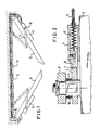
- Fig. 2 eine schematisierte Teilschnittdarstellung eines Türschließers mit einer Einrichtung zur Schließfolgeregelung,
- Fig. 3 eine schematische Draufsicht eines zwischen einem Türschließer und einer Zarge verlaufenden Gestänges mit einer integrierten Vorrichtung zur Schließfolgeregelung,
- Fig. 4 eine Teilschnittdarstellung zur Erläuterung des Funktionsprinzips der Vorrichtung nach Fig. 3,
- Fig. 5 eine schematische Teil-Seitenansicht eines mit einer gesteuerten Festhaltevorrichtung versehenen, an der Zarge befestigten Gestängearms,
- Fig. 6 eine Vorderansicht der Anordnung nach Fig. 5 mit im Schnitt zu sehendem Gestängearm,
- Fig. 7 eine Prinzipdarstellung zur Erläuterung der Wirkungsweise der Festhaltevorrichtung nach den Fig. 5 und 6,
- Fig. 8 eine schematische, teilweise geschnitten gezeigte Darstellung eines hydraulischen Türschließers mit steuerbarer Blockiereinrichtung,
- Fig. 9 eine schematische Darstellung einer weiteren Ausführungsvariante eines hydraulischen Türschließers mit steuerbarer Blockiereinrichtung, und
- Fig. 10 eine schematische Teilschnittdarstellung der An- kupplung eines Bowdenzugs an ein im Schließergehäuse vorgesehenes Ventilorgan.
- 1 is a schematic representation of a two-leaf door with a device for closing sequence control,
- 2 is a schematic partial sectional view of a door closer with a device for closing sequence control,
- 3 shows a schematic top view of a linkage running between a door closer and a frame with an integrated device for closing sequence control,
- 4 shows a partial sectional view to explain the functional principle of the device according to FIG. 3,
- 5 is a schematic partial side view of a link arm provided with a controlled holding device and attached to the frame,
- 6 is a front view of the arrangement of FIG. 5 with the link arm to be seen in section,
- 7 is a schematic diagram to explain the operation of the holding device according to FIGS. 5 and 6,
- 8 shows a schematic illustration, partly in section, of a hydraulic door closer with controllable blocking device,
- 9 shows a schematic illustration of a further embodiment variant of a hydraulic door closer with controllable blocking device, and
- 10 shows a schematic partial sectional view of the coupling of a Bowden cable to a valve member provided in the closer housing.
Die schematische Darstellung nach Fig. 1 zeigt eine zwei- flügelige Tür mit Standflügel 11 und Gangflügel 12, die . in teilweise geöffneter Stellung dargestellt sind. Jeder der beiden Flügel 11, 12 ist mit einem obenliegenden Tür- schließer 2, 2' versehen. Die Achse 10 eines jeden Schließers 2, 2' ist über ein Gestänge 9 mit der Zarge 13 verbunden.1 shows a double-leaf door with passive leaf 11 and
Im Schwenkbereich der schwenklagerseitigen Stirnfläche des Standflügels 11 befindet sich ein Stellglied 14, das bei sich in Schließlage befindendem Standflügel eine erste Stellung und in öffnungsstellung des Standflügels 11 eine zweite Stellung einnimmt. Diese beiden Stellungen bzw. Positionen des Stellglieds 14 werden über ein mechanisches Verbindungsorgan, im dargestellten Beispiel mittels einer Bowdenzuganordnung 5 zum Türschließer 2 des Gangflügels übertragen, um den Schließvorgang des Gangflügels 12 in Abhängigkeit von der Position des Stellglieds 14 und damit in Abhängigkeit von der Position des Standflügels 11 steuern zu können. Der Bowdenzug 5 ist in der Zarge 13 geführt und tritt bei montierter Vorrichtung optisch praktisch nicht und insbesondere nicht störend in Erscheinung.In the swiveling range of the end face of the fixed leaf 11 on the pivot bearing side there is an
Die in Verbindung mit Oben-Türschließern gezeigte Anordnung nach Fig. 1 läßt sich prinzipiell in gleicher Weise bei Boden-Türschließern verwenden.The arrangement shown in connection with top door closers according to FIG. 1 can in principle be used in the same way for floor door closers.
Fig. 2 zeigt eine mechanische Ausführungsform einer Vorrichtung zur Regelung der Schließfolge, wobei auf die Achse 10 des Schließers 2 eine Kurvenscheibe 3 aufgesetzt ist, die durch eine entsprechende Abflachung der AchseFig. 2 shows a mechanical embodiment of a device for regulating the closing sequence, wherein a cam 3 is placed on the
und eine komplementär geformte Aufnahme in der Kurvenscheibe 3 gegen Verdrehen gesichert ist.and a complementarily shaped receptacle in the cam disk 3 is secured against twisting.
Die Kurvenscheibe 3 wird durch eine sich zwischen dieser Scheibe 3 und einem Gestängearm 9 erstreckende Distanzhülse 6 über die zur Gestängefixierung dienende Schraube niedergehalten.The cam disc 3 is held down by a
Mit der Kurvenscheibe 3 wirkt ein Rastmechanismus zusammen, der aus einem in einem Führungsgehäuse 4 verschiebbar gelagerten Rastschieber 8 besteht, welcher unter der Vorspannung einer Druckfeder 17 steht und mit dem Bowdenzug 5 verbunden ist. Das Führungsgehäuse 4 ist vorzugsweise auf die Oberseite des Schließergehäuses 2 aufgeschraubt.A locking mechanism interacts with the cam disc 3, which consists of a
Der Rastschieber 8 greift an der Kurvenscheibe 3 an und wirkt mit einem Kurvenscheibenanschlag 7 zusammen, wobei dieser Anschlag 7 konstruktionsmäßig ausreichend stabil und formmäßig derart ausgebildet wird, daß die Entkopplung von Anschlag 7 und Rastschieber 8 mit vergleichsweise geringen Kräften erfolgen kann. Vorzugsweise verlaufen die miteinander in Eingriff tretenden Flächen von Anschlag 7 und Rastschieber 8 schräg zur Rastschieberlängsachse.The
Die Vorrichtung arbeitet folgendermaßen:
- Bei geöffnetem Standflügel ist der Bowdenzug entlastet, d.h. der
Rastschieber 8 greift an der Kurvenscheibe 3 an, und bei geschlossenem Standflügel ist der Bowdenzug gezogen, d.h. derRastschieber 8 ist entgegen der Vorspannkraft derFeder 7 in das Führungsgehäuse 4 zurückgezogen.
- When the passive leaf is open, the Bowden cable is relieved, ie the
locking slide 8 engages the cam plate 3, and when the passive leaf is closed, the Bowden cable is pulled, ie thelocking slide 8 is retracted into the guide housing 4 against the biasing force of thespring 7.
Werden beide Türen, d.h. Standflügel und Gangflügel geöffnet, so laufen diese beiden Türen, wenn sie nicht festgestellt werden, ganz normal wieder zu. Erst bei einem durch die Kurvenscheibe 3 bzw. durch die Lage des Kurvenscheibenanschlags 7 definierten Winkel wird der Gangflügel gesperrt, da der Rastschieber 8 am Anschlag 7 zur Anlage kommt und dadurch die weitere Schließbewegung des Gangflügels .. blockiert wird.If both doors, ie the passive leaf and the active leaf are opened, these two doors close again as normal if they are not ascertained. Only with one the active leaf is blocked by the cam 3 or the position of the
Bewegt sich der Standflügel in die Schließstellung, dann führt dies zu einem Ziehen des Bowdenzugs 5, damit zu einer Entkopplung zwischen Rastschieber 8 und Anschlag 7 und somit zur Freigabe des Gangflügels in Richtung seiner Schließstellung.If the inactive leaf moves into the closed position, this leads to a pulling of the Bowden
Der durch die Lage des.Anschlags 7 an der Kurvenscheibe 3 definierte Festhaltewinkel des Gangflügels muß so gewählt werden, daß der Standflügel bei blockiertem Gangflügel am Standflügel vorbeilaufen kann. Dies ist bei einem öffnungswinkel des Gangflügels im Bereich von etwa 20° bis 40° möglich, und.in diesem Bereich wird auch der durch die Lage des Anschlags 7 bestimmte Winkel gewählt.The holding angle of the active leaf defined by the position of the
Fig. 3 zeigt eine Variante mit im Schließergestänge integrierter Sperrvorrichtung, die sich vor allem durch leichte Nachrüstbarkeit auszeichnet, da zum Zwecke der Nachrüstung praktisch nur das Gestänge 9, 15 ausgetauscht werden muß.Fig. 3 shows a variant with locking device integrated in the closer linkage, which is characterized above all by easy retrofitting, since practically only the
Dabei ist mit dem Schließerarm 9, der an die Achse 10 des Schließers 2 angeschlossen ist, die Kurvenscheibe 3 drehfest verbunden. Die der Kurvenscheibe 3 zugeordnete Rastvorrichtung ist im Gestängearm 15 untergebracht, in den der Bowdenzug 5 eingeführt ist. Der Gestängearm ist in einem Schwenklagerbolzen 16 mit der Zarge verbunden, während der Schließer 2 am Gangflügel 12 befestigt ist.Here, the cam 3 is rotatably connected to the
Fig. 4 zeigt die Anordnung nach Fig. 3 im geschnittenen und aufgeklappten Zustand. Dabei ist zu sehen, daß die Hülse des Bowdenzugs 5 an der Eintrittsstelle des Bowdenzugs in den Schließerarm 15 an der Schließerarmwandung abgestützt und der Bowdenzug selbst mit dem Rastschieber 8 verbunden ist, der in einer entsprechenden Ausnehmung des-Arms 15 verschiebbar geführt und in Richtung der Kurven- scheibe 3 mittels einer Druckfeder 17 vorgespannt ist.FIG. 4 shows the arrangement according to FIG. 3 in the cut and opened state. It can be seen that the sleeve of the
Neben dem Vorteil der bereits erwähnten einfachen Nachrüstbarkeit der Lösung nach den Fig. 3 und 4 wirkt sich in - der Praxis vorteilhaft aus, daß der an der Zarge festver- legte Bowdenzug 5 nicht mit einer großen Schleife zu dem normalerweise auf der Tür montierten Schließer 2 gelegt werden muß, sondern daß dieser Bowdenzug direkt von der Zarge in das Gestänge bzw. den Schließerarm 15 laufen kann. Da sich der Arm 15 relativ zur Wand weniger als der auf der Tür 12 montierte Schließer 2 bewegt, wird der Bowdenzug 5 wenig beansprucht und seine Leichtgängigkeit nicht beeinträchtigt.In addition to the advantage of the simple retrofitting of the solution according to FIGS. 3 and 4, the advantage in practice is that the
Die Fig. 5 bis 7 zeigen eine Variante mit stufenloser Festhaltung des Gangflügels, und zwar unter Verwendung einer Schlingfeder 18, die mit einem mit dem Gestängearm 15 drehfest verbundenen Schwenklagerbolzen 16 in Form eines Federnfreilaufs zusammenwirkt. Ein Ende 19 dieser Feder 18 ist mit der mit der Zarge 13 verbundenen Lagerhülse für den Gestängearm 15 verbunden, während am anderen Ende 20 der Feder 18 der Bowdenzug angreift, dessen Hülse zargenfest abgestützt ist.5 to 7 show a variant with stepless retention of the active leaf, using a
Diese Abstützung 21 ist in Fig. 6 zu sehen. Das Funktionsprinzip dieser stufenlosen Festhaltevorrichtung ist in Fig. 7 dargestellt. Wird das Ende 20 der Feder 18 mittels des Bowdenzugs 5 in Richtung des Pfeiles 22 gezogen, so kann sich der Bolzen 16 und damit der Gestängearm 15 frei drehen bzw. verschwenken. Wird der Bowdenzug 5 entlastet, so verspannt sich der Schwenklagerbolzen 16 bei einer Drehung in Richtung des PfeiLes 23 in der Feder 18 und wird über das untere, mit der Lagerbuchse fest verbundene .. Ende 19 der Feder 18 festgehalten.This
Bei der in Fig. 8 gezeigten Ausführungsvariante der Erfin- dung erfolgt eine mechanische Blockierung des Schließers bei einem vorzugsweise zwischen 20° und 40° gewählten öffnungswinkel des Gangflügels über ein Blockierglied 26, das die Bewegung des Kolbens 24 im Schließer 2 verhindert. Das Blockierglied 26 steht unter der Wirkung einer Druckfeder 17, welche das Blockierglied.26 in der Weise vorspannt, daß es bei entspanntem Bowdenzug 5 in den links vom Kolben 24 gelegenen Druckraum ragt und eine Sperre für den Kolben 24 bildet. Wird der Bowdenzug 5 betätigt bzw. gezogen, so hat dies ein Zurückziehen des Glieds 26 aus dem Druckraum zur Folge und der Kolben 24 kann sich in Schließrichtung bewegen, was ein Schließen des Schließers zur Folge hat. Die Schließgeschwindigkeit kann dabei über ein Ventil 28 eingestellt werden, das in einem Verbindungskanal 27 zwischen den beiderseits des Kolbens 24 gelegenen Räumen angeordnet ist. Der Kolben 24 ist dabei in üblicher Weise in Schließrichtung durch eine Schließfeder 25 vorgespannt.In the embodiment variant of the invention shown in FIG. 8, the closer is mechanically blocked at an opening angle of the active leaf preferably chosen between 20 ° and 40 ° via a blocking
Die Ausführungsform gemäß Fig. 8 eignet sich insbesondere für solche Einsätze, bei denen der Schließer an der Zarge 13 und nicht auf der Tür montiert wird. Das Verlegen des Bowdenzugs 5 ist in diesem Falle in besonders einfacher Weise möglich.The embodiment according to FIG. 8 is particularly suitable for applications in which the closer is mounted on the
Gemäß einer in der Zeichnung nicht dargestellten Variante kann das Blockierglied 26 über einen Stößel auch von einer Nockenscheibe betätigt werden, die auf einer Stange angeordnet ist, welche in Abhängigkeit von der Bewegung des Standflügels verdrehbar, bzw. in Abhängigkeit von der jeweiligen Position des Standflügels zwischen zwei Schwenklagen-umgesteuert werden kann. Das Schwenken der Nockenscheibe steuert dann das Blockierglied 26 in entsprechender Weise wie dies im Zusammenhang mit Fig. 8 erläutert worden ist.According to a variant not shown in the drawing, the blocking
Bei der Ausführungsvariante gemäß Fig. 9 wird die Bewegung des Schließerkolbens in Abhängigkeit von der jeweiligen Position des dem Standflügel zugeordneten Stellgliedes durch ein Ventil 29 gesteuert, das in einem Strömungskanal 27, 27' zwischen den beiden Druckräumen des Schließers angeordnet ist und über starre oder flexible Bedienelemente zwischen der Schließ- oder öffnungsstellung umsteuerbar ist. In der Schließstellung verhindert das Ventil jeglichen ölverlust zwischen den beiden Druckräumen und damit jegliche Bewegung des Kolbens. Das Ventil 29 ist über eine Druckfeder 17 in die Schließstellung vorgespannt. Eine Bewegung des Schließerkolbens ist damit nicht möglich. Wird das Ventil 29 über den über das Schließergehäuse 2 vorstehenden Stößel 30 betätigt, so wird der zunächst blockierte Kanal geöffnet und die Türe kann in die Schließlage laufen. Das Verschieben des Stößels 30 entgegen der Kraft der Feder 17 erfolgt über einen Konus 31, der auf einer relativ zum Schließer 2 verschiebbaren Stange 32 angebracht ist. Die Linearverschiebung dieser Stange 32 erfolgt wiederum in Abhängigkeit von dem in Fig. 1 gezeigten Stellglied 14.9, the movement of the closer piston is controlled depending on the respective position of the actuator assigned to the passive leaf by a
Unmittelbar benachbart zum Ventil 29 ist im Kanal 27 noch ein weiteres Ventil 28 angeordnet, das es gestattet, den Strömungswiderstand in diesem Kanal zu verändern und damit die Schließgeschwindigkeit zu regulieren.A
Die Ansteuerung eines im Schließer 2 untergebrachten Ventils 29 über eine Bowdenzuganordnung 5, 5' ist in Fig. 10 dargestellt.The control of a
Dabei stützt sich die Hülse 5 des Bowdenzugs an einer Stellschraube 33 eines Schraubkopfes 34 ab, der in eine entsprechende Gewindebohrung des Gehäuses 2 einschraubbar ist. Mittels der Stellschraube 33 kann die Justierung des Bowdenzugs erfolgen.The
Das Ventil 29 ist durch die Feder 17 in die Schließposition vorgespannt, in der ein Durchgang von öl zwischen den Kanalabschnitten 27 und 27' verhindert und damit eine Bewegung des Schließerkolbens blockiert wird. Durch Betätigung des Bowden- zugs wird der Ventilkörper nach links verschoben, und zwar maximal um den durch eine Distanzhülse 35 begrenzten Hub. Da- durch wird der Kanalabschnitt 27 mit dem Kanalabschnitt 27' verbunden, das öl kann ungehindert durch den Kanal über ein nachgeschaltetes Regulierventil abfließen, und der Gangflügel kann sich gedämpft schließen. Diese Ausführungsvariante zeichnet sich durch gute Integrierbarkeit in einem Türschließer, durch Kompaktheit und leichte Justierbarkeit aus.The
Während sich die mechanischen Ausführungsvarianten der Erfindung durch besonders einfachen Aufbau und leichte Nachrüstbarkeit auszeichnen und bei diesen Ausführungsformen auch kein sogenanntes Kriechen des Schließers aufgrund geringer Leckage der Hydraulik bei festgestelltem Schließer auftritt, d.h. ein langsames Zulaufen der jeweiligen Tür sicher verhindert ist, besitzen die Ausbildungsvarianten mit in den Schließer integriertem Ventil und dem Blockierglied die zusätzlichen Vorteile, daß die kompakte Bauform des Schließergehäuses erhalten bleibt, keine komplizierte Montage vor Ort bei Inbetriebnahme der zweiflügeligen Türe, insbesondere Feuerschutztüre nötig ist, da der Schließfolgeregler bereits im Schließer integriert ist und daß eine Verschmutzung eines Steuerglieds oder Steuerventils durch die integrierte Bauweise erschwert wird, was zu einer wartungsfreundlichen Gesamtanordnung führt.While the mechanical design variants of the invention are characterized by a particularly simple construction and easy retrofitting, and in these embodiments there is also no so-called creep of the closer due to low leakage of the hydraulics when the closer is determined, i.e. A slow closing of the respective door is reliably prevented, the training variants with a valve integrated in the closer and the blocking element have the additional advantages that the compact design of the closer housing is retained, no complicated installation on site when the double-leaf door, in particular fire protection door, is required , since the closing sequence controller is already integrated in the closer and that contamination of a control element or control valve is made more difficult by the integrated design, which leads to a maintenance-friendly overall arrangement.
Claims (10)
Priority Applications (1)
| Application Number | Priority Date | Filing Date | Title |
|---|---|---|---|
| AT84106618T ATE34009T1 (en) | 1983-08-16 | 1984-06-08 | DEVICE FOR ADJUSTING THE CLOSING SEQUENCE OF DOUBLE DOORS. |
Applications Claiming Priority (2)
| Application Number | Priority Date | Filing Date | Title |
|---|---|---|---|
| DE19833329543 DE3329543A1 (en) | 1983-08-16 | 1983-08-16 | DEVICE FOR REGULATING THE CLOSING ORDER OF DOUBLE DOORS |
| DE3329543 | 1983-08-16 |
Publications (3)
| Publication Number | Publication Date |
|---|---|
| EP0141902A2 true EP0141902A2 (en) | 1985-05-22 |
| EP0141902A3 EP0141902A3 (en) | 1986-01-22 |
| EP0141902B1 EP0141902B1 (en) | 1988-05-04 |
Family
ID=6206657
Family Applications (1)
| Application Number | Title | Priority Date | Filing Date |
|---|---|---|---|
| EP84106618A Expired EP0141902B1 (en) | 1983-08-16 | 1984-06-08 | Device for controlling the closure sequence of double doors |
Country Status (5)
| Country | Link |
|---|---|
| US (1) | US4583324A (en) |
| EP (1) | EP0141902B1 (en) |
| JP (1) | JPS6043593A (en) |
| AT (1) | ATE34009T1 (en) |
| DE (2) | DE3329543A1 (en) |
Cited By (9)
| Publication number | Priority date | Publication date | Assignee | Title |
|---|---|---|---|---|
| EP0152561A3 (en) * | 1984-02-22 | 1986-05-28 | Geze Gmbh | Holding installation with integrated locking follower controller |
| DE4012358C1 (en) * | 1990-04-18 | 1991-05-16 | Eco Schulte Gmbh & Co Kg, 5750 Menden, De | |
| DE4308560A1 (en) * | 1993-03-18 | 1994-09-22 | Dorma Gmbh & Co Kg | Closing-sequence control for a door self-closing via door closers and comprising a standing wing and a passage wing |
| US5651216A (en) * | 1995-02-07 | 1997-07-29 | Dorma Gmbh & Co. Kg | Door closer for a two-panel door with a closing sequence control mechanism |
| WO2002064927A1 (en) | 2001-02-14 | 2002-08-22 | Dorma Gmbh + Co. Kg | Closing sequence control device |
| DE10107461A1 (en) * | 2001-02-14 | 2002-09-12 | Dorma Gmbh & Co Kg | Closing sequence control device for automatically closing doors, comprises cam plate on fixed wing connected via actuator to brake for movable wing |
| WO2004063508A1 (en) * | 2003-01-09 | 2004-07-29 | Dorma Gmbh + Co. Kg | Hydromechanical closing sequence controller |
| DE10361085B4 (en) * | 2003-01-09 | 2014-06-05 | Dorma Gmbh + Co. Kg | Hydraulic-mechanical closing sequence control |
| EP2886770B1 (en) | 2013-12-17 | 2018-10-31 | GEZE GmbH | Device for regulating the closing sequence of a two-leaf door |
Families Citing this family (36)
| Publication number | Priority date | Publication date | Assignee | Title |
|---|---|---|---|---|
| DE3609565C2 (en) * | 1986-03-21 | 1994-09-22 | Dorma Gmbh & Co Kg | Closing sequence control device for a double-leaf door |
| DE8800394U1 (en) * | 1987-07-17 | 1988-03-24 | Geze Grundstücks- und Beteiligungsgesellschaft mbH, 7250 Leonberg | Device for controlling the closing sequence of double-leaf doors |
| DE3800694A1 (en) * | 1988-01-13 | 1989-07-27 | Geze Gmbh & Co | DEVICE FOR REGULATING THE CLOSING ORDER OF DOUBLE DOORS |
| DE8810389U1 (en) * | 1988-08-17 | 1988-09-29 | Gretsch-Unitas GmbH Baubeschläge, 7257 Ditzingen | Device for controlling the closing sequence of two wings |
| DE3941711B4 (en) * | 1988-12-22 | 2006-10-05 | Geze Gmbh | Device for controlling the closing sequence of double-leaf doors |
| US5046689A (en) * | 1989-04-19 | 1991-09-10 | The Boeing Company | Cowling interlock system |
| US5033234A (en) * | 1990-04-25 | 1991-07-23 | Triangle Brass Manufacturing Company | Door coordinator |
| DE4021313C2 (en) * | 1990-07-04 | 1999-09-16 | Geze Gmbh & Co | Closing sequence control |
| US5222838A (en) * | 1991-07-19 | 1993-06-29 | Jack Kennedy Metal Products And Buildings | Power mine door system |
| US5240349A (en) * | 1991-07-19 | 1993-08-31 | Jack Kennedy Metal Products And Buildings, Inc. | Power mine door system |
| DE9403556U1 (en) * | 1994-03-04 | 1994-07-21 | Eco Schulte GmbH & Co KG, 58706 Menden | Device for regulating the closing sequence of a double-leaf door |
| DE19502761B4 (en) * | 1995-01-30 | 2006-01-05 | Geze Gmbh | Two-leaf door |
| US5582472A (en) * | 1995-05-22 | 1996-12-10 | Kewaunee Scientific Corporation | Solvent storage cabinet |
| DE19540505B4 (en) * | 1995-10-31 | 2013-05-16 | Geze Gmbh | Door closer with automatic closing movement and concealed closer housing |
| DE19650809A1 (en) * | 1996-12-06 | 1998-06-10 | Geze Gmbh & Co | Device for regulating the closing sequence of double-leaf doors |
| FI102100B (en) * | 1997-03-26 | 1998-10-15 | Abloy Oy | Door closing arrangement for double doors |
| US5944399A (en) * | 1998-07-06 | 1999-08-31 | Eagle Manufacturing Company | Safety cabinet with self-closing and sequencing door mechanism |
| FI107345B (en) * | 2000-02-18 | 2001-07-13 | Abloy Oy | Door closing arrangement for double doors |
| FI107634B (en) * | 2000-02-18 | 2001-09-14 | Abloy Oy | Door closure arrangement for double doors |
| JP3363897B2 (en) * | 2001-01-23 | 2003-01-08 | 精工技研株式会社 | Wing opening and closing device for trucks etc. |
| DE10107457B4 (en) * | 2001-02-14 | 2004-02-05 | Dorma Gmbh + Co. Kg | Door coordinator |
| US8225458B1 (en) | 2001-07-13 | 2012-07-24 | Hoffberg Steven M | Intelligent door restraint |
| DE102004007126A1 (en) * | 2004-02-12 | 2005-08-25 | Stabilus Gmbh | Device for the motorized opening and closing of a body part |
| DE202006014936U1 (en) * | 2006-09-28 | 2008-02-21 | Gebr. Bode Gmbh & Co. Kg | Drive device for entry and exit devices, in particular passenger doors, entry ramps, sliding steps and the like. on public transport vehicles |
| US8844195B2 (en) | 2010-06-22 | 2014-09-30 | Cox Architects Pty Ltd | Fire shutter |
| AU2010100647B4 (en) * | 2010-06-22 | 2013-10-10 | Cox Architects Pty Ltd | An Improved Fire Shutter |
| FR2961840B1 (en) * | 2010-06-25 | 2012-08-03 | Somfy Sas | METHOD FOR OPERATING A MOTORIZATION DEVICE OF A DOMOTIC FACILITY COMPRISING A FLAP PROVIDED WITH TWO LEAVES |
| CN106390330B (en) | 2012-02-01 | 2021-10-22 | 贾斯特里特制造有限责任公司 | Safety Cabinets and Interlocking Mechanisms |
| MX358094B (en) | 2012-02-08 | 2018-08-01 | Justrite Mfg Co Llc | Safety cabinet with sequential door-closing system. |
| DE202013100554U1 (en) * | 2013-02-07 | 2014-05-08 | Holzbau Schmid Gmbh & Co. Kg | Door-closing controller for a double-leaf door construction with a fixed leaf and a moving leaf |
| US9243437B1 (en) * | 2013-10-30 | 2016-01-26 | Austin Hardware And Supply, Inc. | Door sequencer |
| DE102014102587A1 (en) * | 2014-02-27 | 2015-08-27 | Dorma Deutschland Gmbh | Closing sequence control for a door wing and a power wing door |
| DE102017112176A1 (en) | 2017-06-02 | 2018-12-06 | Gretsch-Unitas GmbH Baubeschläge | door assembly |
| EP3956537B1 (en) * | 2019-04-19 | 2025-01-29 | Cisaplast S.P.A. | Hinge for doors of refrigerated cabinets |
| DE102021207047A1 (en) | 2021-07-05 | 2023-01-05 | Geze Gmbh | Door locking system and door system |
| US12312857B2 (en) * | 2023-01-16 | 2025-05-27 | Transportation Ip Holdings, Llc | Door actuation system and method |
Family Cites Families (11)
| Publication number | Priority date | Publication date | Assignee | Title |
|---|---|---|---|---|
| US1241478A (en) * | 1915-02-13 | 1917-09-25 | Albert L Beardsley | Door-holder. |
| US1573512A (en) * | 1924-10-06 | 1926-02-16 | Alden J Bush | Door holder |
| US4267619A (en) * | 1972-01-26 | 1981-05-19 | The Stanley Works | Controlled release door holder |
| DE2523154A1 (en) * | 1975-05-24 | 1976-12-09 | Dorma Baubeschlag | Automatic door closer with shaft and solenoid - has spring loaded ratchet for closing shaft and movement damper |
| US4265051A (en) * | 1978-01-12 | 1981-05-05 | Williams Clarence E | Door having improved closing and latching systems |
| US4262448A (en) * | 1979-06-20 | 1981-04-21 | Justrite Manufacturing Company | Safety storage cabinet |
| DE3001407A1 (en) * | 1980-01-16 | 1981-07-23 | Dorma-Baubeschlag Gmbh & Co Kg, 5828 Ennepetal | CLOSING REGULATOR FOR A DOUBLE-LEAF DOOR, IN PARTICULAR FIRE PROTECTION DOOR |
| DE3033496C2 (en) * | 1980-09-05 | 1985-07-25 | Casma di V. Marinoni & Figli, Magenta | Door closer linkage that can be locked in the open position |
| DE3147239A1 (en) * | 1981-11-28 | 1983-06-09 | Liberda GmbH, Wolfsegg | Closing follow-up controller |
| DE3204975C1 (en) * | 1982-02-12 | 1983-05-19 | Echt & Co, Nachf. Schulte Kg, 5750 Menden | Double-leaf door with closing sequence control |
| DE3221534A1 (en) * | 1982-06-08 | 1983-12-08 | Dorma-Baubeschlag Gmbh & Co Kg, 5828 Ennepetal | Gangway-leaf door closer having a device for the closing follow-up control of two-leaf doors |
-
1983
- 1983-08-16 DE DE19833329543 patent/DE3329543A1/en not_active Withdrawn
-
1984
- 1984-06-08 EP EP84106618A patent/EP0141902B1/en not_active Expired
- 1984-06-08 DE DE8484106618T patent/DE3470901D1/en not_active Expired
- 1984-06-08 AT AT84106618T patent/ATE34009T1/en not_active IP Right Cessation
- 1984-07-03 US US06/627,661 patent/US4583324A/en not_active Expired - Fee Related
- 1984-07-23 JP JP59152764A patent/JPS6043593A/en active Pending
Cited By (11)
| Publication number | Priority date | Publication date | Assignee | Title |
|---|---|---|---|---|
| EP0152561A3 (en) * | 1984-02-22 | 1986-05-28 | Geze Gmbh | Holding installation with integrated locking follower controller |
| DE4012358C1 (en) * | 1990-04-18 | 1991-05-16 | Eco Schulte Gmbh & Co Kg, 5750 Menden, De | |
| DE4308560A1 (en) * | 1993-03-18 | 1994-09-22 | Dorma Gmbh & Co Kg | Closing-sequence control for a door self-closing via door closers and comprising a standing wing and a passage wing |
| US5651216A (en) * | 1995-02-07 | 1997-07-29 | Dorma Gmbh & Co. Kg | Door closer for a two-panel door with a closing sequence control mechanism |
| WO2002064927A1 (en) | 2001-02-14 | 2002-08-22 | Dorma Gmbh + Co. Kg | Closing sequence control device |
| DE10107461A1 (en) * | 2001-02-14 | 2002-09-12 | Dorma Gmbh & Co Kg | Closing sequence control device for automatically closing doors, comprises cam plate on fixed wing connected via actuator to brake for movable wing |
| DE10107461C2 (en) * | 2001-02-14 | 2003-07-17 | Dorma Gmbh & Co Kg | Door coordinator |
| DE10147477B4 (en) * | 2001-02-14 | 2005-10-27 | Dorma Gmbh + Co. Kg | Door coordinator |
| WO2004063508A1 (en) * | 2003-01-09 | 2004-07-29 | Dorma Gmbh + Co. Kg | Hydromechanical closing sequence controller |
| DE10361085B4 (en) * | 2003-01-09 | 2014-06-05 | Dorma Gmbh + Co. Kg | Hydraulic-mechanical closing sequence control |
| EP2886770B1 (en) | 2013-12-17 | 2018-10-31 | GEZE GmbH | Device for regulating the closing sequence of a two-leaf door |
Also Published As
| Publication number | Publication date |
|---|---|
| US4583324A (en) | 1986-04-22 |
| EP0141902B1 (en) | 1988-05-04 |
| ATE34009T1 (en) | 1988-05-15 |
| JPS6043593A (en) | 1985-03-08 |
| EP0141902A3 (en) | 1986-01-22 |
| DE3329543A1 (en) | 1985-02-28 |
| DE3470901D1 (en) | 1988-06-09 |
Similar Documents
| Publication | Publication Date | Title |
|---|---|---|
| EP0141902B1 (en) | Device for controlling the closure sequence of double doors | |
| DE3147761C2 (en) | Door closer | |
| DE2924311C2 (en) | ||
| EP1500766A2 (en) | Bifold flap or door lifting apparatus | |
| EP1884614A2 (en) | Hinge unit | |
| EP2069600B1 (en) | Furniture hinge having a damping device | |
| EP1431497B1 (en) | Free running device for a wing control of a door or window | |
| DE20200762U1 (en) | Hinge for furniture | |
| EP0324075B1 (en) | Device for controlling the closure sequence of double-wing doors | |
| DE3221534A1 (en) | Gangway-leaf door closer having a device for the closing follow-up control of two-leaf doors | |
| EP0468176B1 (en) | Hinge for the articulated junction of two wings of a folding door | |
| EP0985794A2 (en) | Drive for a wing of a door, a window or the like | |
| DE6901279U (en) | DOOR CLOSER | |
| EP0505350B1 (en) | Pivoting plate-closure sequence and locking device | |
| DE3609565C2 (en) | Closing sequence control device for a double-leaf door | |
| EP0709536B1 (en) | Drive | |
| EP1247931B1 (en) | Closure sequence controller | |
| DE10107461A1 (en) | Closing sequence control device for automatically closing doors, comprises cam plate on fixed wing connected via actuator to brake for movable wing | |
| EP1544395B1 (en) | Door-closing selector device for double-leave doors | |
| DE8800379U1 (en) | Device for controlling the closing sequence of double-leaf doors | |
| DE9403698U1 (en) | Device for limiting the opening of door leaves | |
| DE8216563U1 (en) | AED WING LOCKER WITH A DEVICE FOR THE CLOSURE CONTROL OF DOUBLE-LEAF DOORS | |
| DE102004062763A1 (en) | Door closer control has drives with arms for doors and lock with fixable locking bar which slides through passage side slideway and has brake | |
| DE2927921A1 (en) | DOOR CLOSER | |
| EP2886770B1 (en) | Device for regulating the closing sequence of a two-leaf door |
Legal Events
| Date | Code | Title | Description |
|---|---|---|---|
| PUAI | Public reference made under article 153(3) epc to a published international application that has entered the european phase |
Free format text: ORIGINAL CODE: 0009012 |
|
| AK | Designated contracting states |
Kind code of ref document: A2 Designated state(s): AT CH DE FR GB LI NL SE |
|
| PUAL | Search report despatched |
Free format text: ORIGINAL CODE: 0009013 |
|
| AK | Designated contracting states |
Kind code of ref document: A3 Designated state(s): AT CH DE FR GB LI NL SE |
|
| 17P | Request for examination filed |
Effective date: 19860224 |
|
| 17Q | First examination report despatched |
Effective date: 19870202 |
|
| GRAA | (expected) grant |
Free format text: ORIGINAL CODE: 0009210 |
|
| AK | Designated contracting states |
Kind code of ref document: B1 Designated state(s): AT CH DE FR GB LI NL SE |
|
| REF | Corresponds to: |
Ref document number: 34009 Country of ref document: AT Date of ref document: 19880515 Kind code of ref document: T |
|
| RAP2 | Party data changed (patent owner data changed or rights of a patent transferred) |
Owner name: GEZE GRUNDSTUECKS- UND BETEILIGUNGSGESELLSCHAFT MB |
|
| GBT | Gb: translation of ep patent filed (gb section 77(6)(a)/1977) | ||
| REF | Corresponds to: |
Ref document number: 3470901 Country of ref document: DE Date of ref document: 19880609 |
|
| ET | Fr: translation filed | ||
| PLBE | No opposition filed within time limit |
Free format text: ORIGINAL CODE: 0009261 |
|
| STAA | Information on the status of an ep patent application or granted ep patent |
Free format text: STATUS: NO OPPOSITION FILED WITHIN TIME LIMIT |
|
| 26N | No opposition filed | ||
| PGFP | Annual fee paid to national office [announced via postgrant information from national office to epo] |
Ref country code: SE Payment date: 19890621 Year of fee payment: 6 |
|
| PGFP | Annual fee paid to national office [announced via postgrant information from national office to epo] |
Ref country code: NL Payment date: 19890630 Year of fee payment: 6 |
|
| PG25 | Lapsed in a contracting state [announced via postgrant information from national office to epo] |
Ref country code: SE Effective date: 19900609 |
|
| PG25 | Lapsed in a contracting state [announced via postgrant information from national office to epo] |
Ref country code: NL Effective date: 19910101 |
|
| NLV4 | Nl: lapsed or anulled due to non-payment of the annual fee | ||
| PGFP | Annual fee paid to national office [announced via postgrant information from national office to epo] |
Ref country code: CH Payment date: 19930719 Year of fee payment: 10 |
|
| PG25 | Lapsed in a contracting state [announced via postgrant information from national office to epo] |
Ref country code: LI Effective date: 19940630 Ref country code: CH Effective date: 19940630 |
|
| EUG | Se: european patent has lapsed |
Ref document number: 84106618.6 Effective date: 19910206 |
|
| REG | Reference to a national code |
Ref country code: CH Ref legal event code: PL |
|
| REG | Reference to a national code |
Ref country code: GB Ref legal event code: IF02 |
|
| PGFP | Annual fee paid to national office [announced via postgrant information from national office to epo] |
Ref country code: GB Payment date: 20030530 Year of fee payment: 20 |
|
| PGFP | Annual fee paid to national office [announced via postgrant information from national office to epo] |
Ref country code: DE Payment date: 20030603 Year of fee payment: 20 Ref country code: AT Payment date: 20030603 Year of fee payment: 20 |
|
| PGFP | Annual fee paid to national office [announced via postgrant information from national office to epo] |
Ref country code: FR Payment date: 20030611 Year of fee payment: 20 |
|
| PG25 | Lapsed in a contracting state [announced via postgrant information from national office to epo] |
Ref country code: GB Free format text: LAPSE BECAUSE OF EXPIRATION OF PROTECTION Effective date: 20040607 |
|
| PG25 | Lapsed in a contracting state [announced via postgrant information from national office to epo] |
Ref country code: AT Free format text: LAPSE BECAUSE OF EXPIRATION OF PROTECTION Effective date: 20040608 |
|
| REG | Reference to a national code |
Ref country code: GB Ref legal event code: PE20 |