EP0141590B1 - Verfahren und Anordnung zum Regenerieren eines sauren Elektrolyten, der zur Dekontaminierung von Komponenten mit radioaktiv kontaminierten Oberflächen benutzt wurde - Google Patents
Verfahren und Anordnung zum Regenerieren eines sauren Elektrolyten, der zur Dekontaminierung von Komponenten mit radioaktiv kontaminierten Oberflächen benutzt wurde Download PDFInfo
- Publication number
- EP0141590B1 EP0141590B1 EP84307185A EP84307185A EP0141590B1 EP 0141590 B1 EP0141590 B1 EP 0141590B1 EP 84307185 A EP84307185 A EP 84307185A EP 84307185 A EP84307185 A EP 84307185A EP 0141590 B1 EP0141590 B1 EP 0141590B1
- Authority
- EP
- European Patent Office
- Prior art keywords
- electrolyte
- acid
- cathode chamber
- chamber
- anode chamber
- Prior art date
- Legal status (The legal status is an assumption and is not a legal conclusion. Google has not performed a legal analysis and makes no representation as to the accuracy of the status listed.)
- Expired - Lifetime
Links
Images



Classifications
-
- G—PHYSICS
- G21—NUCLEAR PHYSICS; NUCLEAR ENGINEERING
- G21F—PROTECTION AGAINST X-RADIATION, GAMMA RADIATION, CORPUSCULAR RADIATION OR PARTICLE BOMBARDMENT; TREATING RADIOACTIVELY CONTAMINATED MATERIAL; DECONTAMINATION ARRANGEMENTS THEREFOR
- G21F9/00—Treating radioactively contaminated material; Decontamination arrangements therefor
- G21F9/001—Decontamination of contaminated objects, apparatus, clothes, food; Preventing contamination thereof
- G21F9/002—Decontamination of the surface of objects with chemical or electrochemical processes
- G21F9/004—Decontamination of the surface of objects with chemical or electrochemical processes of metallic surfaces
-
- C—CHEMISTRY; METALLURGY
- C25—ELECTROLYTIC OR ELECTROPHORETIC PROCESSES; APPARATUS THEREFOR
- C25F—PROCESSES FOR THE ELECTROLYTIC REMOVAL OF MATERIALS FROM OBJECTS; APPARATUS THEREFOR
- C25F3/00—Electrolytic etching or polishing
- C25F3/16—Polishing
- C25F3/22—Polishing of heavy metals
- C25F3/24—Polishing of heavy metals of iron or steel
-
- C—CHEMISTRY; METALLURGY
- C25—ELECTROLYTIC OR ELECTROPHORETIC PROCESSES; APPARATUS THEREFOR
- C25F—PROCESSES FOR THE ELECTROLYTIC REMOVAL OF MATERIALS FROM OBJECTS; APPARATUS THEREFOR
- C25F7/00—Constructional parts, or assemblies thereof, of cells for electrolytic removal of material from objects; Servicing or operating
-
- C—CHEMISTRY; METALLURGY
- C25—ELECTROLYTIC OR ELECTROPHORETIC PROCESSES; APPARATUS THEREFOR
- C25F—PROCESSES FOR THE ELECTROLYTIC REMOVAL OF MATERIALS FROM OBJECTS; APPARATUS THEREFOR
- C25F7/00—Constructional parts, or assemblies thereof, of cells for electrolytic removal of material from objects; Servicing or operating
- C25F7/02—Regeneration of process liquids
Definitions
- the present invention relates to a method and apparatus for regenerating an acid electrolyte that has been used in the decontamination of components with radioactively contaminated surfaces. More specifically, it concerns a method for recovering, by electrodeposition capture, radioactive metal ions in the form of solid metal, which ions dissolve in an acid electrolyte during the process of electrolytic decontamination, the method further serving to regenerate the spent decontaminating electrolyte.
- Radioactive conjugated oxides which may be called "CRUD”
- Radioactively contaminated equipment can be decontaminated by blasting the equipment with ice or dry ice, a high pressure jet of water, ultrasonic cleaning, chemical polishing or electrolytic polishing.
- the electrolytic polishing is the most advantageous method in regard to decontamination and prevention of recontamination, but it presents some problems in the disposal of waste electrolyte.
- the major portion of the radioactive substances that contaminate metals is contained in the CRUD.
- the CRUD is composed of radioactive conjugated oxides which are hard to dissolve in an electrolyte.
- it is possible to separate the CRUD by allowing a DC current to flow between one or more cathodes and an anode formed by the contaminated metal part, the anode and the cathode being immersed in an electrolyte, so that a very thin surface layer of the metal part under the CRUD dissolves in the electrolyte.
- radioactive substances eluted from the contaminated part and existing in the form of metallic ions in the electrolyte cannot be removed by the solid-liquid separation methods mentioned above and therefore they gradually accumulate in the electrolyte, thus increasing the radiation level of the electrolyte. If electrolytic decontamination is continued using an electrolyte in this state, workers are possibly exposed to the radiation and the service life of the electrolyte comes to an end because the electrolytic polishing efficiency is reduced as the concentration of metallic ions dissolved in the electrolyte is increased.
- EP-A-0 125 401 corresponding to US-A--4481089, (neither of which is pre-published), discusses the problems and points out that while electrolytic decontamination in a concentrated aqueous solution of a strong acid such as phosphoric acid or sulphuric acid as electrolyte is superior to electrolysis in a solution of a neutral salt as electrolyte, the treatment of the spent acid electrolyte is complicate and gives rise to high processing costs and a problem of secondary waste disposal. For these reasons, the patentee in that case proposes the use of a neutral salt solution and alternate periods of electrolysis with the object to be decontaminated serving first as the cathode and then as the anode.
- a dilute aqueous solution of a strong acid such as dilute sulphuric acid may be used as an electrolyte for electrolyte polishing decontamination as described.
- This solution effects rapid polishing and it is easily disposed of after use.
- the surface polished using this solution is, however, rough and consequently easily contaminated again. Therefore, use of this solution is limited only to contaminated parts that are to be disposed of rather than reused.
- high concentration acid solutions generally used for electrolytic polishing high concentration sulphuric acids yield a reduced glossy polished surface, but high concentration phosphoric acids and high concentration phosphoric-sulphuric acids yield a more glossy surface.
- EP-A-0075882 corresponding to US-A-4514270, describes a method of regenerating solutions of organic acids used in chemical decontamination (as distinct from electrolytic decontamination), and containing radioactive metal ions, by electrolysis in an electrolytic cell partitioned into an anode chamber and a cathode chamber by a diaphragm, with deposition of the dissolved metal ions as elemental metals on the cathode; but the patentee in that instance warns that the method is not suitable for strongly acidic solutions of inorganic acids because then the efficiency of metal deposition is very low, the cathode current being mostly consumed in the generation of hydrogen gas.
- the reaction that generates hydrogen gas at the capture cathode takes place in preference to the reaction for metal deposition on the capture electrode in the cathode chamber partitioned by the diaphragm, and therefore one needs to lower the hydrogen ion concentration in the cathode chamber to such an extent as to permit metal deposition.
- acid is then diffused into the cathode chamber due to the large gradient of concentration between the anode and the cathode chambers partitioned by the diaphragm.
- a method of regenerating for re-use a spent acid electrolyte solution containing contaminants in the form of radioactive metal ions, especially an inorganic sulphuric and/or phosphoric acid electrolyte that has been used in the electrolyte decontamination of components with surfaces contaminated with radioactive metal compounds comprising subjecting the electrolyte to electrolysis in an electrolytic cell partitioned into an anode chamber and a cathode chamber by a diaphragm, characterised in that the pH of the solution in the cathode chamber is controlled to prevent it either decreasing substantially below or rising substantially above 2 whereby metals are deposited on the cathode rather than evolution of hydrogen gas occurring, while the electrolyte is regenerated for re-use in the anode chamber.
- the invention further provides apparatus for the performance of this method.
- electrolytic decontamination of radioactively contaminated equipment or parts various methods well known for general electrolytic polishing can be employed.
- electrolytic decontamination the volume of the secondary waste can be reduced by selecting a suitable electrolyte in accordance with the objects to be decontaminated.
- First disposable wastes resulting from dismantling of radioactively contaminated equipment and parts
- second equipment, vessels, pipes and tools that are to be reused.
- the electrolyte used for decontamination of the first type may be an inorganic acid aqueous solution of relatively low concentration that is inexpensive and rapid in polishing.
- a suitable inorganic acid is sulphuric acid that does not generate harmful gases in the process of electrolysis.
- the concentration of the sulphuric acid should be high enough to achieve polishing efficiency. About 5 Vol.% is the most suitable for uniform polishing and disposal of waste electrolyte.
- An electrolyte of this concentration is effective in macroscopic polishing but not in microscopic polishing (mirror finish), however. Therefore, an electrolyte for decontamination of the second type that requires microscopic polishing must be a high concentration acid solution, preferably 70% or higher phosphoric acid content.
- the electrolyte is then regenerated by an electrodeposition process in a diaphragm electrolytic cell with pH control.
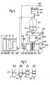
- Fig. 1 shows an example of a plant in accordance with this invention for regenerating an electrolyte after electrolytic decontamination using inorganic acid aqueous solution of a relatively low concentration.
- metallic ions dissolved in the electrolyte are easily deposited on a capture electrode in the form of solid metal, and therefore are isolated in the state of the highest possible concentration. This is advantageous in that waste electrolyte. i.e. the secondary waste to be disposed of after isolating metallic ions, is in small amount.
- the hydrogen ion concentration is still high during the process of electrolytic decontamination.
- the reaction which generates hydrogen gas takes place prior to the reaction for metallic deposition on the capture electrode, but when an electrolyte is diluted to the hydrogen ion concentration that permits metallic deposition, polishing efficiency substantially reduces, making electrolytic decontamination impossible.
- polishing efficiency substantially reduces, making electrolytic decontamination impossible.
- Another method available for isolating metallic ions by deposition is to install an unglazed plate or a similar porous electrolytic diaphragm between the anode and cathode in the electrolytic cell so as to effect a diaphragm electrolysis.
- the hydrogen ion concentration in the electrolyte drops due to the generation of hydrogen gas in the cathode chamber, and metallic ions in the electrolyte deposit on the capture electrode.
- the electrolytic cell is partitioned by an electrolytic diaphragm, and the capture electrode is situated in the cathode chamber.
- a capture electrode surrounded by an electrolytic diaphragm formed by an unglazed cylinder is installed in the electrolytic cell.
- a metallic ion isolating cell that is divided into an anode chamber and a cathode chamber, is installed, with circulation of the electrolyte in the anode chamber during the process of decontamination.
- a DC current is allowed to flow between the insoluble electrode in the anode chamber and the capture electrode in the cathode chamber as the pH of the electrolyte in the cathode chamber is controlled by flow of the electrolyte from the anode chamber into the cathode chamber.
- the electrolyte is regenerated at the same time as isolation by deposition occurs of metallic ions dissolved in the electrolyte and the regenerated electrolyte is returned to the decontaminating electrolytic cell, so that electrolytic decontamination of contaminated objects and isolation by deposition of dissolved metallic ions can be continued semi-permanently.
- metallic ions dissolved in the electrolyte are isolated by deposition while the pH of the electrolyte is controlled by transferring electrolyte having a high hydrogen ion concentration from the anode chamber into the cathode chamber. Therefore, degradation of the deposition process due to an excessive rise in the pH value does not occur.
- a contaminated metal part or object 103 is connected to a positive DC potential and acts as an anode.
- the part 103 is submersed or dipped in the electrolyte 102 of a decontamination electrolytic cell 101, and a plurality of cathodes 104 are installed around the anode.
- a negative DC potential is connected to the cathodes 104 and a DC current is passed between the electrodes in order to perform an electrolytic decontamination of the surface of the contaminated object 103 as previously described.
- the electrolyte 102 is fed by a pump 105 from the electrolytic cell 101 to a filter 106 where suspended substances are removed, and returned through a pipe 107 into the cell 101, thus also agitating the electrolyte in the cell.
- Part of the circulating electrolyte is sent through a branch pipe 108 into the lower level of a metallic ion isolating cell 109 which is divided into an anode chamber 111 and a cathode chamber 112 by an electrolytic diaphragm 110.
- the circulating electrolyte from the branch pipe 108 enters the anode chamber 111 and flows back into the decontamination electrolytic cell 101 through an overflow pipe 113 connected to an upper level of the cell 109.
- An insoluble electrode 114 of, for example, platinum-plated titanium, and a capture electrode 115 of, for example, steel sheet are installed in the anode chamber 111 and cathode chamber 112, respectively.
- Positive and negative DC potentials are connected to the electrodes 114 and 115, and DC current is passed through the electrolyte of the cell and the electrolytic diaphragm 110 between the electrodes.
- the cathode chamber 112 is filled with the electrolyte 102 so that metallic ions dissolved in the electrolyte are deposited on the capture electrode 115. This causes a build-up 115a on the electrode 115.
- the hydrogen ion concentration of the electrolyte in the cathode chamber 112 is high and a large volume of hydrogen gas is generated at the capture electrode 115. Therefore, the metallic ions do not deposit on the electrode 115.
- the amount of hydrogen gas being generated is decreased with an increase in pH value of the electrolyte, and then the metallic ions start to deposit on the electrode.
- the solution in the chamber 112 is agitated by an upward flow of the hydrogen gas generated on the capture electrode 115, and the solution is maintained at substantially pH 2.
- the cells were filled with a 5% sulfuric acid aqueous solution as the electrolyte 102.
- 1OA/dm' DC current was allowed to flow for 15 minutes and stopped for 45 minutes to perform continuous electrolytic polishing of a SUS 304 stainless steel plate as a contaminated object 103 in the decontamination electrolytic cell 101.
- 5A/dm 2 DC current was allowed to flow continuously, while automatically transferring electrolyte, using the meter 116 and the controller 116a, from the anode chamber 111 into the cathode chamber 112, so that the hydrogen ion concentration of the electrolyte in the cathode chamber did not exceed pH 2.
- the apparatus was operated continuously for two weeks to decontaminate the SUS 304 plate by electrolytic polishing and to perform isolation by deposition of metallic ions separated from the SUS 304 plate and dissolved into the electrolyte.
- the result was that the metallic ions deposited on the capture electrode 115 in a stable manner and therefore iron ion concentration in the electrolyte never exceeded 25.2 g/I in the electrolytic cell 101.
- Sulfuric acid ions set free due to deposition of metallic ions in the cathode chamber 112 moved through the electrolytic diaphragm 110 into the anode chamber 111 and bonded with hydrogen ions generated on the insoluble electrods 114, thus being segmented as metal-free sulfuric acid. Therefore, the electric conductivity of the electrolyte did not decrease.
- the dilute inorganic acid aqueous solution electrolyte yields a smooth finished surface but not a mirror finished glossy surface such as would be obtained with a high concentration phosphoric acid electrolyte. For example, if 10A/dm 2 DC current is allowed to flow for 30 minutes to produce electrolytic polishing of the surface of a SUS304 stainless steel plate in phosphoric acid electrolyte containing 50% phosphoric acid and 25% sulfuric acid, a surface with 0.45 11m surface roughness and 418 gloss is obtained.
- One of the convenient methods of making use of the advantages of these two types of electrolyte is to perform electrolytic decontamination in a dilute electrolyte in a first stage, and then to perform electrolytic polishing in a high concentration phosphoric acid solution electrolyte in a second stage so as to obtain a glossy surface.
- the contamination of the high concentration electrolyte can be minimized by this method.
- Fig. 2 shows an example of regenerating a high concentration acid decontamination electrolyte, by electrodeposition.
- an electrolytic cell is divided by a diaphragm into an anode chamber and a cathode chamber.
- the cathode chamber is provided with a capture electrode and filled with electrolyte whose service life is spent.
- the anode chamber is provided with an anode formed by an insoluble electrode and filled with aqueous solution whose pH is adjusted to about 2 by adding acid of the same composition as the electrolyte.
- DC current is allowed to flow through the diaphragm between the anode (the insoluble electrode) and the cathode (the capture electrode) so as to isolate metallic ions dissolved in the spent electrolyte by deposition on the cathode and at the same time to recover the electrolyte as a strong acid solution of the initial concentration.
- the anode chamber in order to separate metallic ions dissolved in the spent electrolyte in the cathode chamber, it is required to remove hydrogen ions in the form of hydrogen gas from free acid that does not bond with metallic ions so as to lower the hydrogen ion concentration. Meanwhile, in order to recover acid solution electrolyte of the same volume and the same concentration as that decomposed in the cathode chamber, it is necessary to transfer anions separated in the cathode chamber into the anode chamber through the diaphragm so that they bond with hydrogen ions generated in solution at the insoluble electrode or anode. Theoretically, the anode chamber should be filled with electrolyte of the same volume as the spent batch transferred to the cathode chamber which anolyte should not contain acid.
- Such neutral electrolyte without acid content would, however, provide poor electric conductivity and make diaphragm electrolysis difficult. It is necessary therefore, to employ a solution having an acid content such as to assure electric conductivity but not to affect the acid concentration of the regenerated electrolyte. In this sense, it is desirable to use a solution of about pH 2 and with the same acid constituent as the electrolyte in a first batch operation, so as to assure good electric conductivity, and to utilize the solution processed in the cathode chamber as the anolyte for a subsequent batch operation.
- An electrodeposition reproducing cell 201 is divided by a diaphragm 202 into a cathode chamber 203 and an anode chamber 206.
- the cathode chamber 203 contains a capture electrode 205 made of steel sheet and is filled with spent electrolyte 204, i.e. radioactive metallic ion-containing high concentration acid electrolyte whose service life is over.
- the anode chamber 206 having substantially the same capacity as the cathode chamber contains an insoluble electrode 208 made, for example, of platinum-plated titanium net and is filled with an anolyte 207 having a hydrogen ion concentration adjusted to about pH 2 by an acid solution of the same composition as the electrolyte so as to have good electric conductivity. Then, DC current is passed between the insoluble electrode 208 (the anode) and the capture electrode 205 (the cathode) so that dissolved metallic ions are deposited on the capture electrode 205, and so that the electrolyte is regenerated in the anode chamber 206.
- an insoluble electrode 208 made, for example, of platinum-plated titanium net and is filled with an anolyte 207 having a hydrogen ion concentration adjusted to about pH 2 by an acid solution of the same composition as the electrolyte so as to have good electric conductivity. Then, DC current is passed between the insoluble electrode 208 (the anode) and the capture electrode 205 (the catho
- the hydrogen ion concentration of the electrolyte in the cathode chamber 203 is so high that a large volume of hydrogen gas is generated on the capture electrode 205, and therefore, metallic ions are not deposited on the capture electrode.
- the hydrogen ion concentration of the electrolyte 204 decreases to about pH 2, however, the hydrogen gas is generated in decreased amount and metallic ions begin to deposit on the capture electrode.
- Anions produced in the cathode chamber 203 then move through the diaphragm 202 into the anode chamber 206 where they bond with hydrogen ions produced by oxygen generation on the insoluble electrode 208 in the anode chamber 206 so as to be regenerated as electrolyte.
- the current supply is continued until the desired result is obtained.
- a pH meter 209 may be installed in the cathode chamber 203 and connected to a controller 209a so that when an excessive rise in the pH is detected by the pH meter 209, a pump 210, actuated by the controller 209a, is operated to feed electrolyte from the anode chamber 206 into the cathode chamber 203, thereby controlling the hydrogen ion concentration of the spent electrolyte to about pH 2 so as to assure efficient electrodeposition.
- the system was operated with spent electrolyte resulting from electrolytic decontamination of SUS 304 stainless steel in an electrolyte containing 75 wt% phosphoric acid. 62.5 g/I of iron ions, 9.75 g/I of chromium ions, 7.75 g/I of nickel ions and 0.21 g/I of cobalt ions were contained dissolved in this spent electrolyte.
- the cathode chamber 203 in Fig. 2 was filled with the spent electrolyte of the above composition and the anode chamber 206 was filled with an anolyte whose hydrogen ion concentration was adjusted to pH 2.
- Diaphragm electrolysis was conducted by supplying 10A/dm z DC current until the total current supply reached 3,500 AH/I.
- 0.045 g/I of iron ions, 0.052 g/I of chromium ions, 0.067 g/I of nickel ions and 0.002 g/I of cobalt ions were left in the spent electrolyte in the cathode chamber 203.
- the electrolyte was recovered as high concentration phosphoric acid solution with 75 wt% phosphoric acid content and containing 1250 g/I of phosphoric acid ions. Namely, electrolyte of substantially the same composition as the original electrolyte was regenerated except that about 20% metallic ions leaked through the diaphragm 202 into the regenerated electrolyte due to diffusion.
- diaphragm electrolysis was conducted according to this example with a spent high concentration acid solution electrolyte composed of 70 Vol. % of 85% phosphoric acid and 30 Vol.% of 98% sulfuric acid.
- the spent electrolyte resulted from electrolytic decontamination carried out in the above electrolyte and contained iron ions, chromium ions, nickel ions and cobalt ions in the same amount as for Example I.
- the result obtained was similar to that in Example I.
- the electrolyte regenerated in the anode chamber 206 contained phosphoric acid and sulfuric acid in the same mixing ratio as for the original electrolyte.
- Fig. 3 shows another system in accordance with the present invention in which electrolyte decontamination is performed in a high concentration acid solution electrolyte.
- electrolyte used in decontamination is successively regenerated by electrodeposition.
- an electrodeposition regenerating cell is divided by a diaphragm into an anode chamber and a cathode chamber. Electrolyte from an electrolytic decontamination cell is introduced into the cathode chamber of the electrodeposition regenerating cell using a pH controller so that hydrogen ion concentration in the cathode chamber is maintained at pH 2 at all times. To assure continuous introduction, the electrodeposition regenerating cell and the electrolytic decontaminating cell are connected with each other. When DC current is allowed to flow through the diaphragm between the capture electrode in the cathode chamber and the insoluble electrode in the anode chamber, the pH value of the electrolyte in the cathode chamber increases as hydrogen ions are discharged as hydrogen gas from the electrolyte.
- introduction of the electrolyte from the electrolytic decontaminating cell into the cathode chamber starts when the pH value exceeds approximately 2, and stops when the pH value drops to approximately 2 or below.
- a high concentration acid solution regenerated in the anode chamber of the electrodeposition regenerating cell is fed into the electrolytic decontamination cell in the same amount for pH adjustment. This operation is automatically repeated under the control of the pH controller (PHC).
- PLC pH controller
- radioactive metallic ions are separated without delay from the electrolyte with the pH value maintained at 2 and deposited on the capture electrode in the cathode chamber and hydrogen gas is generated.
- Anions separated by generation of hydrogen gas move through the diaphragm into the anode chamber where they bond with hydrogen ions generated on the insoluble electrode or anode so as to be regenerated as a high concentration acid solution.
- Electrodeposition regeneration is automatically initiated because of circulation of the solution.
- the cathode and the anode chambers are automatically topped-up with water by the use of level gauges provided in each of the chambers so as to always maintain the levels constant.
- the makeup water is required only in the amount sufficient to compensate for the loss due to generation of hydrogen and oxygen as well as that due to evaporation of water during operation.
- this example has made possible a continuous system integrating the electrolytic decontamination process and the electrodeposition regenerating process.
- equipment or a part that is radioactive on its surface is decontaminated using a high concentration acid solution as electrolyte while the electrolyte is continuously fed to the electrodeposition regeneration process under certain conditions.
- the electrodeposition regenerating cell radioactive metallic ions separated from the electrolyte are allowed to deposit on the capture electrode in the form of radioactive metal which is easily disposed of.
- the regenerated high concentration acid solution is fed back into the electrolytic decontamination cell in the same amount as the electrolyte fed to the electrodeposition regenerating cell for regeneration.
- the radiation dose of the electrolyte is always maintained at a low level and metallic ion leakage to the regenerated electrolyte is minimized in the electrodeposition regenerating process.
- the radiation dose and the metallic ion content in the electrolyte are both maintained at low levels due to the renewal of the electrolyte in the electrolytic decontamination process.
- the apparatus according to this example requires a smaller number of devices and therefore is simpler in operation.
- the hydrogen ion concentration of the electrolyte in the electrodeposition regenerating cell is maintained at pH 2 from the beginning of the operation.
- it is necessary to operate the apparatus for a time to allow the hydrogen generating reaction to occur, before the pH value in the cathode chamber reaches 2 at which time the metallic ions begin to deposit on the capture electrode whereas in this example, the apparatus is operated with the cathode chamber being filled with a solution of pH 2 and the anode chamber filled with high concentration acid solution from the beginning.
- the electrodeposition regenerating cell 301 used for the electrodeposition regenerating process according to this example is divided by a diaphragm 302 into a cathode chamber 303 and an anode chamber 304.
- the cathode chamber 303 contains a capture electrode 305 made, for example, of an iron sheet and is filled with ordinary water 307 at the beginning.
- the anode chamber 304 contains an insoluble electrode 306 made, for example, of platinum-plated titanium net and is filled with a high concentration acid solution 308 having the same components and concentration as the electrolyte used for the electrolytic decontamination process at the beginning. DC current is passed between the electrodes 305 and 306.
- the electrolytic decontamination cell 309 used for the electrolytic decontamination process equipment or a part bearing radioactivity on the surface is provided as an anode 310 and an insoluble electrode of the same type as the electrode 306 is provided as a cathode 311.
- the cell is filled with a high concentration acid solution used as electrolyte 312.
- DC current is passed between the electrodes 310 and 311 to perform electrolytic polishing so that at least part of the radioactive substance is removed from the anode surface and suspended in the electrolyte and the other part thereof is dissolved as radioactive metallic ions in the electrolyte, thus completing the decontamination process.
- a pH detecting auxiliary bath 313 is installed on the upper part of the cathode chamber 303 of the electrodeposition regenerating cell 301.
- the auxiliary bath 313 is provided with a pH meter sensor or electrode 315 that is connected to a pH controller 314 set at pH 2.
- Water 307 in the cathode chamber 303 is circulated by means of a circulation puvp 316 through the auxiliary bath 313 for detection of pH value amd then back to the chamber 303.
- An injection pipe 318 equipped with an injection pump 317 leads from the cell 309 to the auxiliary bath 313 (or the cathode chamber 303), the injection pump 317 being connected to be operated by the pH controller 314 so as to continuously inject electrolyte 312 from the electrolytic decontaminating cell 309 into the cathode chamber 303.
- a suction pipe 320 equipped with a suction pump 319 leads from the anode chamber 304 to the electrolytic decontaminating cell 309, the suction pump 319 being connected to be operated by the pH controller 314.
- the capacity of the anode chamber 304 with the present circulating system may be moderately small.
- the cathode chamber 303 and the anode chamber 304 are filled with ordixary water and a high concentration acid solution, respectively, at the beginning of operation.
- the circulation pump 316 is then operated to circulate water 307 in the cathode chamber 303 and the bath 313. Since the pH value of the water 307 in the cathode chamber is higher than 2 at this stage, the pH controller 314 actuates the intercoupling injection pump 317, resulting in electrolyte 312 from the electrolytic decontaminating process being introduced into the cathode chamber 303 (or the auxiliary bath 313).
- the suction pump 319 is also actuated by the pH controller 314 whereby solution 308 in the anode chamber is drawn off and fed back into the electrolytic decontaminating cell 309 in the same amount as electrolyte from the electrolytic decontaminating cell 309 is fed into the cathode chamber 303.
- the injection pump 317 and the suction pump 319 are actuated again so as to adjust the pH value in the cathode chamber 303 to 2.
- the above operation is automatically repeated so that electrolyte is regenerated by electrodeposition substantially continuously and constantly.
- solenoid-operated valves 323 and 324 are controlled by level gauges 321 and 322 provided in the chambers 303 and 304. The valves 323 and 324 are connected in waterlines 325 and water is automatically supplied to maintain a constant level in the chambers.
- Radioactively contaminated SUS 304 stainless steel was used as an anode 310 to be decontaminated, and 75 wt% of phosphoric acid solution was used as an electrolyte to perform the electrolytic decontamination.
- 38 g/I of iron ions, 8.8 g/I of chromium ions, 6.8 g/I of nickel ions and 0.092 g/I of cobalt ions were dissolved in the spent electrolyte.
- the cathode chamber 303 of the electrodeposition regeneration cell 301 was initially filled with ordinary water and the anode chamber 304 was filled with 75 wt% phosphoric acid solution devoid of metallic ions at the beginning.
- 8A1dm 2 current was supplied to start the electrolytic operation of the cell 301 so as to check the change with time in the concentration of residual metallic ions in the solution 307 in the cathode chamber and the solution 308 in the anode chamber.
- the end result was that the solution 307 in the cathode chamber contained 0.005 to 0.060 g/I of iron ions.
- the level of metallic ions was maintained very low both in the cathode chamber 303 and in the anode chamber 304. Moreover, current efficiency was stable around 10% during the above operation.
- an electrolyte of a different composition from that given in Example III was temporarily injected into the cathode chamber 303 under the same conditions as above. Namely, 4.84 g/I of iron ions 1.47 g/I of chromium ions, 0.34 g/I of nickel ions and 0.0126 g/I of cobalt ions were contained in the electrolyte. These values are all smaller than those for the electrolyte above.
- Residual metallic ions in the solution 307 in the cathode chamber iron ion 0.0032 g/I, chromium ion 0.0096 g/I, nickel ion 0.0014 g/I, cobalt ion 0.0003 g/I.
- Residual metallic ions in the solution 308 in the anode chamber iron ion 0.016 g/I, chromium ion 0.0025 g/I, nickel ion 0.004 g/I, cobalt ion 0.002 g/I.
- the object is rinsed by spraying it with the solution from the electrodeposition regenerating cell or, preferably, the solution 307 in the cathode chamber that contains a lower level of metallic ions, or it is dipped in the solution 307 in the cathode chamber for a preliminary rinsing and then it is washed in water.
- the solution used for spray-rinsing is returned to the cathode chamber 303.
- the radioactively contaminated electrolyte thus entering the solution 307 in the cathode chamber presents no problem because it is part of the electrolyte to be employed in the electrodeposition regeneration.
- the level of radioactivity due to the metallic ions dissolved in the secondary rinsing water is much lower than that encountered by conventional methods and is within the safety limit.
- phosphoric acid is extracted, by a solvent, from the high concentration phosphoric acid decontaminating electrolyte used for an electrolytic decontamination process prior to feeding the electrolyte into the electrodeposition regenerating cell.
- the resultant solution after extraction (or electrolyte whose phosphoric acid content is decreased) is fed into the cathode chamber of the electrodeposition regenerating cell.
- the extracted phosphoric acid is further extracted, by water, from the solvent, and the resultant solution (or phosphoric acid aqueous solution containing substantially no metallic ion) is fed into the anode chamber of the electrodeposition regenerating cell.
- the resultant solution or phosphoric acid aqueous solution containing substantially no metallic ion
- metallic ions in the solution are captured by electrodeposition in the cathode chamber, and the phosphoric acid concentration in the solution is increased so that of the initial electrolyte in the anode chamber so it may be reused as a decontaminating electrolyte.
- the solvent for liquid-liquid extraction of phosphoric acid from phosphoric acid aqueous solution is generally taken from the group comprising isopropyl ether, ethylene monomethyl ether, normal butyl alcohol, isoamyl alcohol, methyl isobutyl ketone or butyl acetate. Since these organic solvents evaporate due to the heat of the decontaminating electrolyte and are inflammable, they are not suitable as phosphorus extracting agents to be used in the process of electrodeposition regeneration. Among various phosphorus extracting agents studied, water-insoluble and noncombustible tributyl phosphate (TBP) is found to be most effective as a phosphorus extracting agent for use in the process of electrodeposition regeneration of decontaminating electrolyte.
- TBP water-insoluble and noncombustible tributyl phosphate
- Tributyl phosphate known as a metal extracting agent, is usually used for extracting uranium from nitric acid. It is effective in extracting phosphoric acid but hardly extracts iron, nickel, chromium, cobalt or their metallic ions from a decontaminating electrolyte. By further extraction in water, phosphoric acid and any metallic ions are almost completely extracted from this extracting agent. It can be used repeatedly without make-up because of its high boiling point and small evaporation loss.
- a high concentration acid of the phosphoric acid series is used as an electrolyte in the process of electrolytic decontamination.
- An object 402 which is radioactively contaminated on its surface is set in the electrolyte in electrolytic decontamination cell 401 and connected as an anode to a DC source such as an AC-DC rectifier (not shown). DC current is passed between the object and cathodes 403 in the electrolyte so as to decontaminate the surface of the contaminated object 402.
- the decontaminating electrolyte containing radioactive metallic ions separated from the surface of the object 402 is suctioned off by a pump 404 into the extractive separating bath 412 where the electrolyte is separated into two solutions: one solution is an electrolyte with less phosphoric acid content obtained after extraction of phosphoric acid by a solvent and the other is a phosphoric acid aqueous solution substantially free from metallic ions obtained by further extraction of the extracted phosphoric acid from the solvent by water.
- the above electrolyte and phosphoric acid aqueous solution thus obtained are fed into the cathode chamber 406 and the anode chamber 407, respectively, of the electrodeposition regenerating cell 405.
- the extractive separating bath 412 where solvent extraction and aqueous extraction of phosphoric acid are performed is filled with a solvent (S) to about half level or volume. Operation of the solvent extraction and the aqueous extraction is described in the following, with reference to Figs. 5a to 5d.
- a decontaminating electrolyte 413 (Fig. 5a) of the same volume as the capacity of the anode chamber 407 is fed by the pump 404 from the electrolytic decontaminating cell 401 into the extractive separating bath 412 where the electrolyte 413 is stirred for a time by a motor-driven agitator 414 (Fig. 4) so that phosphoric acid is extracted by the solvent (S).
- the phase of the solution 415, that separates and settles in the lower layer in the bath 412 is discharged through a discharge valve 416 into the cathode chamber 406.
- a liquid level controller 418a may be provided to automatically control the valve 418 and the liquid level.
- a feed water valve 420 at the outlet of a reservoir 419 is opened to supply the extractive separating bath 412 with water 421, and the agitator 414 is again actuated to mix the water with the solvent (S) in the bath 412, thereby extracting phosphoric acid from the solvent (S).
- the agitator 414 is then stopped, and the aqueous phosphoric acid solution 422, separated and settled in the lower layer, is discharged through a discharage valve 423 into the anode chamber 407 to fill it to its upper limit level. Since the volume of the aqueous solution 422 is larger than that of the body of decontaminating electrolyte 413, a major portion of the solution is left undischarged in the extractive separating bath 412.
- a liquid level control 423a may be mounted in the chamber 407 and connected to automatically control the valve 423.
- the conductivity meter 417 may also be connected to an automatic controller 417a that is connected to control the operation of the valve 423. The controller 417a would turn off the valve 423 when all of the solution 422 is drained from the bath 412.
- the level control function is disabled and the discharge valve 423 is closed.
- the current supply is continued, however, until substantially all of the metallic ions and the phosphoric acid ions are removed from the solution in the cathode chamber 406.
- the electrolyte 413 fed from the electrolytic decontaminating cell 401 is thus regenerated as a high concentration phosphoric acid solution of substantially the same volume.
- Water is supplied through a feed water valve 424 to the solution in the chamber 407, as required, to adjust the phosphoric acid concentration to that of the initial electrolyte before feeding the whole volume of the solution in the anode chamber 407 by the pump 411 back into the electrolytic decontaminating cell 401, thus completing the electrodeposition regenerating process.
- the phase 415 after solvent extraction in the bath 412 contains a small percentage of phosphoric acid when it is discharged into the cathode chamber 406.
- the solution is further diluted by makeup water supplied through the feed water valve 418. Therefore, the current flow is started with the cathode chamber 406 filled with a solution having a decreased hydrogen ion concentration.
- the length of time required before electrodeposition starts is considerably reduced in this example.
- a solvent extracting bath 430, an extractive solution separating bath 431, an aqueous extracting bath 432 and a second extractive solution separating bath 433 are separately installed in such a manner that the solution overflows from one bath to the next bath.
- the solvent (S) is continuously circulated by a pump 434 from the separating bath 433 to the extracting bath 430 and the solutions in the extracting baths 430 and 432 are stirred at all times by the agitators 435, 436.
- Electrolyte is continuously fed by the pump 404 from the electrolytic decontamination cell 401 into the extracting bath 430 where phosphoric acid is continuously extracted by the solvent (S).
- the resultant solution after extraction 415, separated and settled in the lower layer of the extractive solution separating bath 431, is sent through a supply valve 437 into the cathode chamber 406 so that the hydrogen ion concentration of the solution in the cathode chamber 406 is always maintained at pH 2.
- the solvent phase (S) flows from the separating bath 431 to the inverse extracting bath 432 where phosphoric acid is back- extracted by water supplied through a feed water valve 420.
- the resultant aqueous acid solution 422, separated and settled in the lower layer of the separating bath 433, is sent through the supply valve 438 into the anode chamber 407, thereby controlling the liquid level in the anode chamber.
- the feed water valve 420 is operated in accordance with a level control in the separating bath 433 so that water is automatically supplied from the reservoir 419 into the extracting bath 432 in amount equivalent to the discharge of the phase 415 in the separating bath 431 and the phase 422 in the separating bath 433.
- the pH control is disabled so as to stop the addition of the solution 415, when the liquid level reaches the uppermost limit.
- a liquid level control 437a and a pH control 437b for the chamber 406 are connected to the valve 437 in order to control the liquid level.
- a valve 441 in the circulation line of the pump 439 is opened to feed part of the solution from the cathode chamber 406 to the reservoir 419 so as to lower the liquid level when substantially no metallic ions and phosphoric acid ions are left in the liquid in the cathode chamber 406.
- the aqueous acid solution 422 is automatically supplied to compensate for the water loss in the anode chamber 407, while the solution in the anode chamber 407 is fed back into the electrolytic decontaminating cell 401 as regenerated electrolyte, through a pump 411 with the feed rate controlled by means of an electric conductivity meter 417a. Meanwhile, electrolyte is fed from the electrolytic decontaminating cell 401 into the extracting bath 430 in the same amount as the regenerated electrolyte fed back from the anode chamber 407 to the electrolytic decontaminating cell 401, thus continuously performing electrodeposition regeneration of electrolyte.
- the liquid phase 415 whose phosphoric acid content is decreased, is introduced into the cathode chamber 406 in this system. Therefore, compared with the method as described earlier in which the electrolyte is directly introduced from the electrolytic decontaminating cell 401 into the cathode chamber 406, the electrodeposition regenerating capacity is improved in this example.
- phosphoric acid in the decontaminating electrolyte fed from the electrolytic decontaminating cell 401 flows directly into the anode chamber 407 after the solvent extraction and aqueous extraction processes, thus saving the electrical energy required for moving the phosphoric acid from the cathode chamber 406 through the diaphragm 408 to the anode chamber 407 during the process of electrodeposition regeneration.
- a large volume of aqueous extraction water may be used, which however in turn leads to increase in the volume of the resultant liquid phase 422 to be processed in the anode chamber 407.
- the speed of the electrodeposition regeneration becomes limited by the rate of water loss due to decomposition and evaporation in the anode chamber 407.
- This problem can be solved by incorporating evaporation into the process of increasing the phosphoric acid concentration as performed in the anode chamber 407. Heating the solution in the anode chamber 407, however, causes the functional effectiveness of the diaphragm 408 to be lowered, resulting in the leakage of hydrogen ions from the anody chamber 407 into the cathode chamber 406.
- Fig. 7 shows a system in which evaporation is incorporated into the process of concentrating the phosphoric acid in the repeated phase 422.
- the solution 422 discharged from the separating bath (412 or 433) into a receiver 450 is fed to a vapor compression concentrating unit 451 so as to concentrate the phosphoric acid.
- the concentrator 452 is a vessel or a pipe that is glass lined on its inner wall.
- a compressor 453 suck vapor from the concentrator 452 for depressurization, as well as compressing the vapor, and compression heat in the vapor is transferred to the solution in the concentrator 452 through a condenser jacket 454 or a similar heat transferring tube provided with a glass liner on its outer wall, so that the solution 422 is concentrated by evaporation at reduced pressure and at a low temperature.
- concentration by evaporation is achieved with little energy consumption and without the need for a heat source or cooling water.
- the concentrated solution in the concentrator is transferred by a pump 455 into the anode chamber 407.
- the condensate in the jacket 454 is sent to the reservoir 419 to be used as aqueous extraction water.
- 40 cc of TBP sovlent was poured into 10 cc of the above-mentioned electrolyte so as to extract phosphoric acid.
- 50 cc of water was poured into the resultant TBP obtained after the solvent extraction so as to perform aqueous extraction of the phosphoric acid.
- 10 cc of the above-mentioned electrolyte was poured into the TBP recovered from the aqueous extraction.
- 10cc of electrolyte decreased to 7 cc after extraction of phosphoric acid by 40 cc of TBP which increased to 43 cc.
- the 43 cc of TBP then decreased to about 40 cc, the initial volume, when recovered by adding 50 cc of water for aqueous extraction of phosphoric acid so that about 53 cc of aqueous acid solution was obtained.
- Components as shown in the table below were contained in 10 cc of the electrolyte (A) and 7 cc of the resultant solution after extraction (B), 53 cc of the aqueous and solution (C) and 40 cc of the TBP recovered (D) after the 2nd and the 5th solvent extraction and aqueous extraction.
- electrodeposition regeneration performance is more than twice that obtained by the method in the previous examples.
- the systems described herein are preferably operated within the temperature range of from approximately normal room temperature up to approximately 50°C.
- the diaphragms may be types that are well known to those skilled in the electrolysis art.
- an unglazed ceramic plate may be used, and in the systems of Figs. 2-4, 6 and 7, an ion exchange membrane may be used.
- phosphoric acid in the electrolyte is directly transferred into the anode chamber of the electrodeposition regeneration cell through the process of solvent and aqueous extraction, thus reducing the time required for electrodeposition regeneration or increasing the electrodeposition regeneration capacity.
- regenerated electrolyte and solvent can be repeatedly used. This helps solve the problem of waste liquid disposal which confronts the most effective electrolytic decontamination process employing high concentration acid electrolyte of the phosphoric acid series. That is, the amount of radioactive secondary waste is significantly reduced.
- methods of regenerating electrolyte in the electrolytic decontamination of waste are described in various embodiments, but these methods are also available for regenerating solutions used in the chemical decontamination of waste that contain radioactive metallic ions.
Landscapes
- Chemical & Material Sciences (AREA)
- Engineering & Computer Science (AREA)
- Chemical Kinetics & Catalysis (AREA)
- Electrochemistry (AREA)
- Materials Engineering (AREA)
- Organic Chemistry (AREA)
- Metallurgy (AREA)
- Food Science & Technology (AREA)
- General Engineering & Computer Science (AREA)
- High Energy & Nuclear Physics (AREA)
- Physics & Mathematics (AREA)
- Life Sciences & Earth Sciences (AREA)
- General Chemical & Material Sciences (AREA)
- Cleaning And De-Greasing Of Metallic Materials By Chemical Methods (AREA)
- Electrolytic Production Of Metals (AREA)
Claims (20)
Applications Claiming Priority (6)
| Application Number | Priority Date | Filing Date | Title |
|---|---|---|---|
| JP19811483A JPS6089600A (ja) | 1983-10-21 | 1983-10-21 | 除染電解液の再生方法 |
| JP198114/83 | 1983-10-21 | ||
| JP37466/84 | 1984-02-28 | ||
| JP3746684A JPS60179700A (ja) | 1984-02-28 | 1984-02-28 | 除染電解液の連続再生方法 |
| JP11784784A JPS60260899A (ja) | 1984-06-07 | 1984-06-07 | リン酸系除染電解液の電着再生方法 |
| JP117847/84 | 1984-06-07 |
Publications (3)
| Publication Number | Publication Date |
|---|---|
| EP0141590A2 EP0141590A2 (de) | 1985-05-15 |
| EP0141590A3 EP0141590A3 (en) | 1987-04-01 |
| EP0141590B1 true EP0141590B1 (de) | 1991-01-30 |
Family
ID=27289477
Family Applications (1)
| Application Number | Title | Priority Date | Filing Date |
|---|---|---|---|
| EP84307185A Expired - Lifetime EP0141590B1 (de) | 1983-10-21 | 1984-10-18 | Verfahren und Anordnung zum Regenerieren eines sauren Elektrolyten, der zur Dekontaminierung von Komponenten mit radioaktiv kontaminierten Oberflächen benutzt wurde |
Country Status (3)
| Country | Link |
|---|---|
| US (1) | US4615776A (de) |
| EP (1) | EP0141590B1 (de) |
| DE (1) | DE3484045D1 (de) |
Families Citing this family (18)
| Publication number | Priority date | Publication date | Assignee | Title |
|---|---|---|---|---|
| JPH0734434B2 (ja) * | 1986-06-16 | 1995-04-12 | 日産自動車株式会社 | 半導体基板のエツチング装置 |
| US5171409A (en) * | 1986-07-18 | 1992-12-15 | Omya S.A. | Continuous process of separating electrically charged solid, pulverulent particles by electrophoresis and electroosmosis |
| EP0261255B1 (de) * | 1986-09-20 | 1989-03-15 | KGB Kernkraftwerke Gundremmingen Betriebsgesellschaft mbH | Verfahren zum Aufbereiten einer wässrigen Phosphorsäurelösung |
| US4861444A (en) * | 1988-09-06 | 1989-08-29 | Schoessow Glen J | Process for treating radioactive material to make it safe for disposal |
| JPH0427113A (ja) * | 1990-04-23 | 1992-01-30 | Tadahiro Omi | レジスト処理装置、レジスト処理方法及びレジストパターン |
| US5078842A (en) * | 1990-08-28 | 1992-01-07 | Electric Power Research Institute | Process for removing radioactive burden from spent nuclear reactor decontamination solutions using electrochemical ion exchange |
| FR2696864B1 (fr) * | 1992-10-13 | 1994-12-23 | Gradient Rech Royallieu | Procédé d'électro-décontamination anodique de l'intérieur de corps creux métalliques, notamment de tubes de circuits primaires de centrale nucléaire, et installation de mise en Óoeuvre dudit procédé. |
| US5306399A (en) * | 1992-10-23 | 1994-04-26 | Electric Power Research Institute | Electrochemical exchange anions in decontamination solutions |
| DE4420139C1 (de) * | 1994-06-09 | 1995-12-07 | Kraftanlagen En Und Industriea | Verfahren zur elektrochemischen Dekontamination von radioaktiv belasteten Oberflächen von Metallkomponenten aus kerntechnischen Anlagen |
| US5614077A (en) * | 1995-04-10 | 1997-03-25 | Electro-Petroleum, Inc. | Electrochemical system and method for the removal of charged species from contaminated liquid and solid wastes |
| US7384529B1 (en) | 2000-09-29 | 2008-06-10 | The United States Of America As Represented By The United States Department Of Energy | Method for electrochemical decontamination of radioactive metal |
| KR100371564B1 (ko) * | 2000-10-27 | 2003-02-07 | 삼성테크윈 주식회사 | 금속표면처리장치와 이를 이용한 금속표면처리방법 |
| JP4462146B2 (ja) * | 2004-09-17 | 2010-05-12 | 栗田工業株式会社 | 硫酸リサイクル型洗浄システムおよび硫酸リサイクル型過硫酸供給装置 |
| FR2937054B1 (fr) * | 2008-10-13 | 2010-12-10 | Commissariat Energie Atomique | Procede et dispositif de decontamination d'une surface metallique. |
| US9546433B1 (en) | 2015-11-24 | 2017-01-17 | International Business Machines Corporation | Separation of alpha emitting species from plating baths |
| US9359687B1 (en) | 2015-11-24 | 2016-06-07 | International Business Machines Corporation | Separation of alpha emitting species from plating baths |
| EP3494090B1 (de) * | 2016-08-04 | 2021-08-18 | Dominion Engineering, Inc. | Unterdrückung von radionuklidablagerung auf kernkraftwerkkomponenten |
| CN120810052B (zh) * | 2025-09-12 | 2025-11-21 | 浙江沃乐科技股份有限公司 | 一种废旧锂电电解液全回收的装置和方法 |
Citations (1)
| Publication number | Priority date | Publication date | Assignee | Title |
|---|---|---|---|---|
| EP0075882A2 (de) * | 1981-09-25 | 1983-04-06 | Hitachi, Ltd. | Verfahren zum Regenerieren von Reinigungslösungen |
Family Cites Families (17)
| Publication number | Priority date | Publication date | Assignee | Title |
|---|---|---|---|---|
| US1590596A (en) * | 1920-10-08 | 1926-06-29 | Taylor Lab Inc | Production of colloidal material |
| US3320175A (en) * | 1961-07-05 | 1967-05-16 | Gen Dynamics Corp | Processing of radioactive liquids |
| US3515655A (en) * | 1967-09-15 | 1970-06-02 | Israel Defence | Electrolytic decontamination of radioactively contaminated equipment |
| GB1142776A (en) * | 1967-09-29 | 1969-02-12 | Szmuel Raviv | Decontamination of radioactively contaminated equipment |
| US3764503A (en) * | 1972-01-19 | 1973-10-09 | Dart Ind Inc | Electrodialysis regeneration of metal containing acid solutions |
| US3922231A (en) * | 1972-11-24 | 1975-11-25 | Ppg Industries Inc | Process for the recovery of fission products from waste solutions utilizing controlled cathodic potential electrolysis |
| US3905885A (en) * | 1973-06-13 | 1975-09-16 | United States Steel Corp | Method for the electrolytic conditioning of metal tubes |
| DE2449588C2 (de) * | 1974-10-18 | 1985-03-28 | Kernforschungszentrum Karlsruhe Gmbh, 7500 Karlsruhe | Verfahren zur Zersetzung einer wäßrigen, radioaktiven Abfallösung mit gelösten, anorganischen und organischen Inhaltsstoffen |
| DD128122A1 (de) * | 1976-10-21 | 1977-11-02 | Juergen Bosholm | Verfahren zur aenderung der borsaeurekonzentration in kreislaufwaessern kerntechnischer anlagen |
| US4226695A (en) * | 1978-10-20 | 1980-10-07 | Environmental Sciences Associates, Inc. | Electrochemical processing system |
| FR2456371A1 (fr) * | 1979-05-07 | 1980-12-05 | Commissariat Energie Atomique | Procede de decontamination en ruthenium d'effluents radio-actifs liquides et dispositif pour la mise en oeuvre de ce procede |
| US4468305A (en) * | 1979-05-08 | 1984-08-28 | The Electricity Council | Method for the electrolytic regeneration of etchants for metals |
| US4193853A (en) * | 1979-05-15 | 1980-03-18 | The United States Of America As Represented By The United States Department Of Energy | Decontaminating metal surfaces |
| US4318786A (en) * | 1980-03-10 | 1982-03-09 | Westinghouse Electric Corp. | Electrolytic decontamination |
| US4401532A (en) * | 1981-05-28 | 1983-08-30 | Jackson Opha L | Radioactive decontamination apparatus and process |
| JPS59154400A (ja) * | 1983-02-23 | 1984-09-03 | 株式会社日立製作所 | 放射性汚染金属の除染方法 |
| US4481090A (en) * | 1984-01-23 | 1984-11-06 | The United States Of America As Represented By The United States Department Of Energy | Decontaminating metal surfaces |
-
1984
- 1984-10-17 US US06/661,696 patent/US4615776A/en not_active Expired - Fee Related
- 1984-10-18 EP EP84307185A patent/EP0141590B1/de not_active Expired - Lifetime
- 1984-10-18 DE DE8484307185T patent/DE3484045D1/de not_active Expired - Lifetime
Patent Citations (1)
| Publication number | Priority date | Publication date | Assignee | Title |
|---|---|---|---|---|
| EP0075882A2 (de) * | 1981-09-25 | 1983-04-06 | Hitachi, Ltd. | Verfahren zum Regenerieren von Reinigungslösungen |
Also Published As
| Publication number | Publication date |
|---|---|
| EP0141590A2 (de) | 1985-05-15 |
| EP0141590A3 (en) | 1987-04-01 |
| US4615776A (en) | 1986-10-07 |
| DE3484045D1 (de) | 1991-03-07 |
Similar Documents
| Publication | Publication Date | Title |
|---|---|---|
| EP0141590B1 (de) | Verfahren und Anordnung zum Regenerieren eines sauren Elektrolyten, der zur Dekontaminierung von Komponenten mit radioaktiv kontaminierten Oberflächen benutzt wurde | |
| US4652352A (en) | Process and apparatus for recovering metals from dilute solutions | |
| CN106929857A (zh) | 含铜酸性蚀刻液循环再生回用设备及方法 | |
| JPH0780466A (ja) | 金属イオンおよび硫酸を含有する水溶液の再生のための方法および装置 | |
| CN107059010A (zh) | 含铜碱性蚀刻液循环再生回用设备及方法 | |
| CN101974756A (zh) | 废微蚀液再生与铜回收装置 | |
| EP0475622A1 (de) | Verfahren zur Entfernung radioaktiver Lasten aus von in Kernreaktoren entstehenden verbrauchten Dekontaminierungslösungen durch elektrochemischen Ionenaustausch | |
| CA1131162A (en) | Electrolytically detinning electrolyte and removing foreign metal ions by cation exchanger | |
| CN120019176A (zh) | 一种结合电解溶铜的不溶性阳极镀铜工艺优化方法及装置 | |
| CN106219830A (zh) | 一种电镀重金属废水零排放系统及方法 | |
| JP7320160B2 (ja) | 放射性使用済イオン交換樹脂の除染方法及び装置 | |
| US4618428A (en) | Process for recovery of zinc from plating waste solutions | |
| JP5684626B2 (ja) | 電解除染方法及びそれに用いる装置 | |
| JPH0688275A (ja) | 金属イオン及び硫酸含有水溶液の再生方法及びその使用方法及び装置 | |
| US6506294B1 (en) | Process for regeneration of electrolytes from pickle liquor, in particular of NA2S04 from pickle liquor for stainless steel | |
| JPH0324997B2 (de) | ||
| JPS60179700A (ja) | 除染電解液の連続再生方法 | |
| CN116393463A (zh) | 次氯酸钠发生器电解槽电极除垢的系统及除垢方法 | |
| JPH0557560B2 (de) | ||
| JPH11237495A (ja) | 放射性廃液の処理方法とその装置 | |
| CN108658321B (zh) | 扩散渗析处理硝酸型退锡废液的系统及方法 | |
| RU2110860C1 (ru) | Способ дезактивации контура многократной принудительной циркуляции водографитовых ядерных реакторов | |
| JPH0631857B2 (ja) | 電解除染方法 | |
| JPH031639B2 (de) | ||
| Hillis | The Electrolytic Regeneration of Spent Ferric Chloride Etchant |
Legal Events
| Date | Code | Title | Description |
|---|---|---|---|
| PUAI | Public reference made under article 153(3) epc to a published international application that has entered the european phase |
Free format text: ORIGINAL CODE: 0009012 |
|
| AK | Designated contracting states |
Designated state(s): DE FR GB SE |
|
| PUAL | Search report despatched |
Free format text: ORIGINAL CODE: 0009013 |
|
| AK | Designated contracting states |
Kind code of ref document: A3 Designated state(s): DE FR GB SE |
|
| 17P | Request for examination filed |
Effective date: 19870822 |
|
| 17Q | First examination report despatched |
Effective date: 19890421 |
|
| RAP1 | Party data changed (applicant data changed or rights of an application transferred) |
Owner name: SHINKO PANTEC CO., LTD. |
|
| GRAA | (expected) grant |
Free format text: ORIGINAL CODE: 0009210 |
|
| AK | Designated contracting states |
Kind code of ref document: B1 Designated state(s): DE FR GB SE |
|
| REF | Corresponds to: |
Ref document number: 3484045 Country of ref document: DE Date of ref document: 19910307 |
|
| ET | Fr: translation filed | ||
| PLBE | No opposition filed within time limit |
Free format text: ORIGINAL CODE: 0009261 |
|
| STAA | Information on the status of an ep patent application or granted ep patent |
Free format text: STATUS: NO OPPOSITION FILED WITHIN TIME LIMIT |
|
| 26N | No opposition filed | ||
| EAL | Se: european patent in force in sweden |
Ref document number: 84307185.3 |
|
| PGFP | Annual fee paid to national office [announced via postgrant information from national office to epo] |
Ref country code: GB Payment date: 19951009 Year of fee payment: 12 |
|
| PGFP | Annual fee paid to national office [announced via postgrant information from national office to epo] |
Ref country code: FR Payment date: 19951010 Year of fee payment: 12 |
|
| PGFP | Annual fee paid to national office [announced via postgrant information from national office to epo] |
Ref country code: SE Payment date: 19951017 Year of fee payment: 12 |
|
| PGFP | Annual fee paid to national office [announced via postgrant information from national office to epo] |
Ref country code: DE Payment date: 19951026 Year of fee payment: 12 |
|
| PG25 | Lapsed in a contracting state [announced via postgrant information from national office to epo] |
Ref country code: GB Effective date: 19961018 |
|
| PG25 | Lapsed in a contracting state [announced via postgrant information from national office to epo] |
Ref country code: SE Effective date: 19961019 |
|
| GBPC | Gb: european patent ceased through non-payment of renewal fee |
Effective date: 19961018 |
|
| PG25 | Lapsed in a contracting state [announced via postgrant information from national office to epo] |
Ref country code: FR Effective date: 19970630 |
|
| PG25 | Lapsed in a contracting state [announced via postgrant information from national office to epo] |
Ref country code: DE Effective date: 19970701 |
|
| EUG | Se: european patent has lapsed |
Ref document number: 84307185.3 |
|
| REG | Reference to a national code |
Ref country code: FR Ref legal event code: ST |