EP0141280B1 - Vorrichtung zum Herstellen von Reissverschlüssen mit Deckbändern - Google Patents
Vorrichtung zum Herstellen von Reissverschlüssen mit Deckbändern Download PDFInfo
- Publication number
- EP0141280B1 EP0141280B1 EP84111829A EP84111829A EP0141280B1 EP 0141280 B1 EP0141280 B1 EP 0141280B1 EP 84111829 A EP84111829 A EP 84111829A EP 84111829 A EP84111829 A EP 84111829A EP 0141280 B1 EP0141280 B1 EP 0141280B1
- Authority
- EP
- European Patent Office
- Prior art keywords
- guide
- chain
- slider
- rows
- coupling elements
- Prior art date
- Legal status (The legal status is an assumption and is not a legal conclusion. Google has not performed a legal analysis and makes no representation as to the accuracy of the status listed.)
- Expired
Links
Images


Classifications
-
- A—HUMAN NECESSITIES
- A44—HABERDASHERY; JEWELLERY
- A44B—BUTTONS, PINS, BUCKLES, SLIDE FASTENERS, OR THE LIKE
- A44B19/00—Slide fasteners
- A44B19/42—Making by processes not fully provided for in one other class, e.g. B21D53/50, B21F45/18, B22D17/16, B29D5/00
- A44B19/60—Applying end stops upon stringer tapes
-
- A—HUMAN NECESSITIES
- A44—HABERDASHERY; JEWELLERY
- A44B—BUTTONS, PINS, BUCKLES, SLIDE FASTENERS, OR THE LIKE
- A44B19/00—Slide fasteners
-
- A—HUMAN NECESSITIES
- A41—WEARING APPAREL
- A41H—APPLIANCES OR METHODS FOR MAKING CLOTHES, e.g. FOR DRESS-MAKING OR FOR TAILORING, NOT OTHERWISE PROVIDED FOR
- A41H37/00—Machines, appliances or methods for setting fastener-elements on garments
- A41H37/06—Setting slide or glide fastener elements
-
- A—HUMAN NECESSITIES
- A44—HABERDASHERY; JEWELLERY
- A44B—BUTTONS, PINS, BUCKLES, SLIDE FASTENERS, OR THE LIKE
- A44B19/00—Slide fasteners
- A44B19/42—Making by processes not fully provided for in one other class, e.g. B21D53/50, B21F45/18, B22D17/16, B29D5/00
-
- A—HUMAN NECESSITIES
- A44—HABERDASHERY; JEWELLERY
- A44B—BUTTONS, PINS, BUCKLES, SLIDE FASTENERS, OR THE LIKE
- A44B19/00—Slide fasteners
- A44B19/42—Making by processes not fully provided for in one other class, e.g. B21D53/50, B21F45/18, B22D17/16, B29D5/00
- A44B19/62—Assembling sliders in position on stringer tapes
Definitions
- the present invention relates to an apparatus for automatically manufacturing a succession of slide fasteners with flies from a continuous slide fastener chain having a pair of intermeshed rows of coupling elements with element-free spaces therein and stringer tapes supporting the rows of coupling elements, respectively, with the flies sewn to one of the tapes, comprising
- the present invention seeks to provide an apparatus for automatically manufacturing a succession of slide fasteners with flies and sliders from a slide fastener chain with such flies sewn thereto in advance of application of said sliders.
- an apparatus of the type mentioned above characterized by
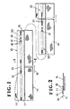
- a slide fastener chain 10 is composed of a pair of continuous stringer tapes 11, 11 supporting intermeshed rows of discrete coupling elements 12 on confronting longitudinal edges thereof with an element-free space or gap 13 in the intermeshed . rows of coupling elements 12.
- a fly 14 wider than the chain 10 is sewn to one of the stringer tapes 11 by two rows of sewing threads 15 along a transversely substantially central portion of the fly 14. -The chain 10 with the stitched fly 14 is progressively processed as follows:
- the slide fastener chain 10 with the fly 14 can be processed into the slider fastener 22 with the fly 14 by an apparatus generally designated by the reference numeral 25 in Figures 3 and 4.
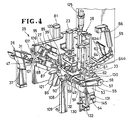
- the apparatus 25 essentially comprises a fly folder 26, a slider applicator 27, and a bottom stop applicator and chain cutter 28, which are arranged in the order named along a feed path 29 for the slide fastener chain 10 and mounted on a bed or base 30.
- the feed path 29 is primarily defined by a guide roller assembly 31 in the fly folder 26, a feed roller assembly 32 disposed downstream of the slider applicator 27, and a discharge roller assembly 33 disposed downstream of the bottom stop applicator and chain cutter 28.
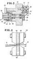
- the guide roller assembly 31 is composed of a pair of upper and lower idling rollers 34, 35 for guiding the intermeshed rows of coupling elements 12 sandwiched therebetween.
- the upper roller 34 is rotatably mounted by a shaft 36 secured to a vertical support plate 37 mounted on the bed 30.
- the lower roller 35 is mounted on a shaft 38 extending through the vertical support plate 37 and supporting thereon a brake mechanism 39.
- the brake mechanism 39 includes a disk 40 keyed to the shaft 38 for rotation therewith, a brake drum 41 with a brake shoe 42 force-fitted thereover and fixedly mounted in an attachment plate 43 mounted on the vertical support plate 37, and a clutch plate 44 axially movably attached to the brake drum 41 by pins 45.
- An electromagnet 46 is mounted in the vertical support plate 37 closely to the disk 40. In response to energization of the electromagnet 46, the clutch plate 44 can be pressed against the disk 40 to stop rotation of the guide roller assembly 31 for thereby interrupting the travel of the chain 10.
- the fly 14 starts being progressively folded by an inclined guide plate 47 before reaching the guide roller assembly 31 and is folded completely on itself after moving past the guide roller assembly 31, as illustrated in Figure 5.
- the feed roller . assembly 32 comprises a pair of upper and lower rollers 48, 49 for feeding the intermeshed rows-of coupling elements 12 therebetween.
- the upper roller 48 is rotatably mounted on a bracket 50 ( Figure 4) which is movable vertically by a first fluid cylinder 23 to bring the upper roller 48 toward and away from the lower roller 49.
- the lower roller 49 is rotatably mounted by a shaft 51 in a bearing 52 mounted on a block 53.
- the shaft 51 supports on an end thereof a sprocket 54 which is driven via an endless chain 55 by a sprocket 56 mounted on an end of a shaft 57 of the discharge roller assembly 33.
- the upper and lower rollers 48, 49 have toothed or otherwise roughened peripheral surfaces 58, 59, respectively, for engaging and driving the intermeshed rows of coupling elements 12.
- a one-way clutch 60 is disposed between the shaft 51 and the lower roller 49 for rotating the lower roller 49 only in a direction to feed the intermeshed rows of coupling elements 12.
- the discharge roller assembly 33 is composed of a pair of laterally spaced upper rollers 61, 61 and a lower roller 62 coacting with the upper rollers 61, 61 for discharging a completed slide-fastener in sandwiching relation.
- Each of the upper rollers 61, 61 is rotatably mounted on one end of a lever 63 pivotably connected by a pin 64a to a bracket 64 mounted on a vertical mount plate 65.
- the other end of the lever 63 is pivotably connected to a piston rod of a second fluid cylinder 66 supported on the vertical mount plate 65.
- the levers 63, 63 are pivotably movable to bring the respective upper rollers 61, 61 into and out of engagement with the lower roller 62, in response to operation of the second fluid cylinder 66.
- the upper rollers 61, 61 are normally urged against the lower roller 62 by means of a pair of tension coil springs 63a, 63a acting between the respective levers 63, 63 and the vertical mount plate 65.
- the levers 63, 63 are loosely connected to the piston rod of the cylinder 66 such that the levers 63, 63 are pivotally movable against the bias of the respective springs 63a, 63a when the chain 10 is passed between the upper and lower rollers 61, 62.
- the lower roller 62 is supported on the shaft 57 which is rotatably supported on the vertical mount plate 65 and driven to rotate by a motor 67 mounted in the bed 30 through a drive mechanism 68.
- the drive mechanism 68 includes a pulley 69 rotatably mounted on an end of the shaft 57 remote from the sprocket 56 and rotatable by a belt 70 trained around the pulley 69 and a pulley (not shown) coupled to the motor 67.
- a clutch plate 71 is axially movably mounted by a pin 72 on the pulley 69.
- a disk 73 supporting an electromagnet 74 is keyed to the shaft 57 in axially confronting relation to the clutch plate 71.
- the lower roller 62 is axially interposed between a pair of set collars 75, 76 and resiliently pressed therebetween by a pair of springs 24 (one being shown) axially acting on the set collar 75.
- a pinion 77 is mounted by a one-way clutch 78 on the shaft 57 and held in mesh with a rack 80 which is vertically movable by a third fluid cylinder 81 ( Figures 3 and 4). 1
- the slider applicator 27 is composed of the feed path 29, a chain splitter 85, a slider supply unit 86, and a tape edge inserter 87.
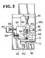
- the levers 91, 91 have a pair of downward fingers 93, 93 for normally contacting an upper surface of the intermeshed rows of coupling elements 12 under the resilient force of a spring 94 acting between the arm 89 and the chain guide 88. Therefore, when any one of the element-free spaces 13 between adjacent lengths of coupling elements 12 reaches the fingers 93, 93, the fingers 93, 93 are displaced downwardly into the element-free space 13 under the force of the spring 94. The fingers 93, 93 will then be lifted out of the space 13 by a fourth cylinder 95 which. depresses a rear end of the arm 89 against the resiliency of the spring 94.
- the fingers 93, 93 are normally urged toward each other by a tension spring 93a connected at opposite ends to the respective levers 91, 91, as shown in Figure 10.
- Another lever 96 is vertically pivotably mounted by a pivot pin 97 on a bracket 65a secured to the mount plate 65, the lever 96 being positioned above the arm 89.
- the lever 96 has a front wedge 98 directed downwardly between the fingers 93, 93.
- the lever 96 is operatively coupled by a pin 100 to a bracket 65b fixed to a piston rod of a fifth fluid cylinder 99, which will be actuated to move the wedge 98 into a lower position between the fingers 93, 93 or into an upper position above the fingers 93, 93.
- a detector plate 101 is positioned laterally of the rear end of the arm 89 for substantially horizontal movement about a pin 102, the detector plate 101 being normally urged by a spring 103 to move toward the arm 89.
- the detector plate 101 has a shoulder or step 104 facing upwardly and disposed adjacent to the arm 89 and an inclined cam surface 105 progressively projecting laterally in an overhanging relation to the lever 96.
- a detector rod 106 extends from the detector plate 101 away from the cam surface 105 and has an end normally engaging a sensor 107.
- the rear end of the arm 89 is raised until it clears the shoulder 104, whereupon the detector plate 101 is turned to the right ( Figure 9).
- the detector rod 106 now disengages from the sensor 107, which produces an electric signal indicative of the depression of the fingers 93, 93 into the space 13.
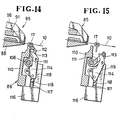
- the wedge 98 is lowered to spread the fingers 93, 93 against the bias of the tension spring 93a ( Figure 11) for thereby splitting the intermeshed rows of coupling elements 12 into disengaged rows from the trailing end of the space 13.
- the slider supply unit 86 is disposed below the downstream end of the chain splitter 85 and angularly movably supported on a horizontal shaft 108 mounted on a post 109 vertically disposed on the bed 30.
- a slider holder 110 is securely fitted over the shaft 108, and a clip 111 is rotatably mounted on the shaft 108 for holding the pull tab 19 of a slider 17 against the slider holder 110, the clip 111 having a through-hole 112.
- a lever 114 angularly movably mounted by a pin 115 on the slider holder 110 has a locking prong 113 for engaging in the hole 20 in the pull tab 19 through the hole 112 in the clip 111.
- the locking prong 113 is forced into the hole 20 in the pull tab 19 by a sixth fluid cylinder 116 having a piston rod 117 acting on the lever 114 through a steel ball 118.
- the locking prong 113 is normally urged to move in a direction out of the pull tab hole 20 under the resiliency of a tension spring 119 acting between the slider holder 110 and the lever 114.
- Sliders 17 are successively delivered from a chute 82 ( Figure 3) to the slider holder 110.
- the shaft 108 is angularly moved back and forth through about 90 degrees to move the slider holder 110 between substantially horizontal and vertical positions, the angular movement of the shaft 108 being effected by a pinion (not shown) fixed to the shaft 108 and meshing with a rack (not shown) actuatable by a fluid cylinder (not shown).
- the slider holder 110 receives one slider 17 at a time from the chute 82 with the shoulders 18 of the slider 17 directed upwardly as shown irf Figure 10 when the slider holder 110 is in the horizontal position ( Figure 8).
- the tape edge inserter 87 is disposed above the feed path 29 between the chain splitter 85 and the feed roller assembly 32, as shown in Figure 3.
- the tape edge inserter 87 comprises a substantially horizontal rod 121 secured to a piston rod 129 ( Figure 12) of a seventh fluid cylinder 120 mounted on the mount plate 65.
- the horizontal rod 121 extends substantially perpendicularly to the feed path 29, and is movable downwardly by the seventh fluid cylinder 120 for depressing engagement with the chain 10 ( Figure 13).
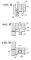
- the bottom stop applicator and chain cutter 28 generally comprises, as shown in Figure 16, a casing 122 mounted on the mount plate 65, and a punch 123 and a cutter 124 vertically movably disposed in the casing 122 and drivable by an eighth fluid cylinder 125 mounted on the mount plate 65.
- the punch 123 is positioned in another cutter 126 having cutter blades 127 one of which cuts off, upon depression, a bottom stop blank wire 147 supplied horizontally below the punch 123, as shown in Figure 17.
- a blank wire length as severed by the cutter blade 127 is formed into a bottom stop 21 by coaction of the lowering punch 123 and a wire bender 128 located therebelow, as shown in Figure 18.
- the formed bottom stop 21 is then applied to the leading end of the intermeshed rows of coupling elements 12 by the punch 123 which is continuously depressed, while at the same time the chain 10 is transversely cut off across the element-free space 13 adjacent to the leading end of the intermeshed rows of coupling elements 12.
- a vertical stop bar 130 is angularly movably mounted on an end of a lever 131 pivotably mounted by a pin 132 on the mount plate 65.
- the stop bar 130 has an upper end normally slidably held against a lower surface of the intermeshed rows of coupling elements 12, and a lower end normally engaging a sensor 133.
- the stop bar 130 is moved upwardly under the bias of a spring 144 acting on the lever 131 for projection into the space 13.
- the upper end of the stop bar 130 is slightly displaced downstream due to the movement of the chain 10, whereupon the lower end of the stop bar 130 disengages from the sensor 133 which issues a signal to de-energize the motor 67.
- a ninth fluid cylinder 145 is mounted on the mount plate 65 for acting on the lever 131 to lower the stop bar 130 out of the space 13 when the chain 10 is to be fed along again.
- the lever 131 has an adjustment bolt 146 for adjusting the interval which the stop bar 130 is vertically movable.
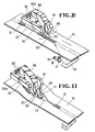
- FIG. 19 there is a substantially U-shaped element guide 138 pivotably mounted on a shaft 136 and including front and rear guide legs 137, 135 disposed forward and rearward, respectively, of the feed roller assembly 32.
- the front and rear guide legs 137, 135' have guide grooves 143, 134, respectively, opening downwardly and aligned with the feed path 29.
- the element guide 138 is normally urged to turn clockwise ( Figures 19 and 21) about the shaft 136 under the bias of a spring 139 acting on a rear end of the element guide 138.
- the bracket 50 on which the upper feed roller 48 is rotatably mounted has a vertical bolt 140 vertically aligned with the rear guide leg 135 for depressing the rear guide leg 135 when the upper feed roller 48 is lowered.
- the element guide 138 is turned clockwise under the resiliency of the spring 139 to cause the rear guide leg 135 to be lifted and the front guide leg 137 to be lowered.
- the bracket 53 on which the lower feed roller 45 is rotatably mounted has an upper element guide base 142 with an upwardly opening guide groove 141 aligned with the feed path 29.
- the guide groove 143 in the front guide leg 137 and the guide groove 141 in the element guide base 142 jointly define a guide slot ( Figure 21) for guiding the intermeshed rows of coupling elements 12 therethrough.
- the lower discharge roller 62 has a pair of axially spaced roller portions 62a, 62b of equal diameters which are vertically aligned with the upper rollers 61, 61, respectively. Since the levers 63, 63 are connected pivotably and loosely connected to the piston rod of the cylinder 66, the upper rollers 61, 61 are vertically movably away from the respective roller portions 62a, 62b of the lower roller 62 so as to define a gap 83 between one of the upper rollers 61 and the lower portion 62b which is greater than a gap 84 between the other upper roller 61 and the lower portion 62a. The wider gap 83 allows the folded fly 14 of the slider fastener 22 to smoothly pass between the upper roller 61 and the lower roller portions 62b.
- the fifth cylinder 99 ( Figure 8) is actuated to retract its piston rod, whereupon the wedge 98 is lowered to spread the fingers 93, 93 apart to open the space 13 and split open the leading end of the rows of coupling elements 12, as shown in Figure 11.
- the slider supply unit 86 is turned counterclockwise to position the slider 17 in the space 13 ( Figure 8). Retracting movement of the piston rod of the cylinder 99 causes the rear end of the lever 96 to engage the cam surface 105 and to urge the detector plate 101 to rotate against the bias of the spring 103 until the detector rod 106 engages the sensor 107, as shown in Figure 9.
- the fourth cylinder 95 is actuated to extend its piston rod, whereupon the arm 89 is rotated counterclockwise ( Figure 8) about the pin 90 against the bias of the spring 94 to thereby move the fingers 93, 93 upwardly away from the element-free space 13.
- the confronting inner edges of the stringer tapes 11, 11 are now inserted into the slider 17 through side slots therein.
- the rod 121 of the tape edge inserter 87 is lowered to depress the chain 10 so that the tape edges which may have engaged an upper slider surface will enter the slider 17, as illustrated in Figures 12 and 13.
- the rack 80 ( Figure 7) is then actuated by the third fluid cylinder 81 to turn the lower discharge roller 62 through a certain angular interval against the braking force effected by the brake mechanism 39.
- the tower-feed roller 49 is also turned by the chain 55 in synchronism with the lower discharge roller 62.
- the chain 10 is advanced slightly to cause the rows of coupling elements 12 to enter the slider 17 through the open shoulders 18, 18, respectively, whereupon the slider 17 is placed on the rows of coupling elements 12.
- the brake mechanism 39 is inactivated, and the sixth fluid actuator 116 is inactivated to move the locking prong 113 away from the slider holder 110 for thereby releasing the slider 17, as shown in Figure 15.
- the upper feed roller 48 is raised by the first fluid cylinder 23, and the clutch disk 73 is engaged with the clutch plate 71 with the result that the lower discharge roller 62 is driven by the motor 32 through the drive mechanism 68 ( Figure 7) to feed the chain 10 with the slider 17 mounted thereon.
- the leading end of the -rows of coupling elements 12 is engaged by the stop bar 130, the lower discharge roller 62 is stopped. At this time, the slider 17 on the chain 10 has moved past the rear guide leg 135 which has been lifted.
- the feed roller assembly 32 engages and drives the rows of coupling elements 12 so that the chain 10 can be fed along reliably regardless of the fly 14 sewn to one of the tapes 11. Since the chain 10 is kept under tension by the brake mechanism 39 when the slider 17 is to be mounted, the tape edges as they are kept taut are depressed by the rod 121 and reliably brought into the slider 17.
- the element guide 138 can accurately guide the rows of coupling elements 12 at all times alternately with the guide legs 135, 137 while allowing the slider 17 to pass therethrough.
- the discharge roller assembly 33 can discharge the completed slide fastener 22 reliably without causing any jam since the fly 14 can smoothly move through the wider gap 83 between the upper roller 61 and the lower roller portion 62b.
Claims (15)
Applications Claiming Priority (4)
| Application Number | Priority Date | Filing Date | Title |
|---|---|---|---|
| JP58188753A JPS6080401A (ja) | 1983-10-07 | 1983-10-07 | フライ付き連続スライドフアスナ−チエ−ンへのスライダ−挿通装置 |
| JP188753/83 | 1983-10-07 | ||
| JP194496/83 | 1983-10-18 | ||
| JP58194496A JPS6085704A (ja) | 1983-10-18 | 1983-10-18 | フライ付きスライドフアスナ−成形機におけるフアスナ−チエ−ン案内装置 |
Publications (3)
| Publication Number | Publication Date |
|---|---|
| EP0141280A2 EP0141280A2 (de) | 1985-05-15 |
| EP0141280A3 EP0141280A3 (en) | 1985-10-30 |
| EP0141280B1 true EP0141280B1 (de) | 1988-07-06 |
Family
ID=26505128
Family Applications (1)
| Application Number | Title | Priority Date | Filing Date |
|---|---|---|---|
| EP84111829A Expired EP0141280B1 (de) | 1983-10-07 | 1984-10-03 | Vorrichtung zum Herstellen von Reissverschlüssen mit Deckbändern |
Country Status (11)
| Country | Link |
|---|---|
| EP (1) | EP0141280B1 (de) |
| KR (1) | KR860000519B1 (de) |
| AU (1) | AU557957B2 (de) |
| BR (1) | BR8405128A (de) |
| CA (1) | CA1231227A (de) |
| DE (1) | DE3472526D1 (de) |
| ES (1) | ES536893A0 (de) |
| FI (1) | FI77144C (de) |
| GB (1) | GB2147945B (de) |
| HK (1) | HK21189A (de) |
| SG (1) | SG80988G (de) |
Families Citing this family (3)
| Publication number | Priority date | Publication date | Assignee | Title |
|---|---|---|---|---|
| JPH074294B2 (ja) * | 1986-06-25 | 1995-01-25 | ワイケイケイ株式会社 | スライダ−保持装置 |
| JPH0675522B2 (ja) * | 1987-04-25 | 1994-09-28 | 吉田工業株式会社 | スライドファスナーの仕上げ装置 |
| CN114474224B (zh) * | 2021-12-31 | 2024-02-02 | 泰安中科生产力促进有限公司 | 一种环境空气监测采样滤膜智能裁剪设备 |
Family Cites Families (2)
| Publication number | Priority date | Publication date | Assignee | Title |
|---|---|---|---|---|
| US3570104A (en) * | 1969-09-18 | 1971-03-16 | Scovill Manufacturing Co | Method and apparatus for making a continuous series of fly pieces |
| US4236292A (en) * | 1978-05-26 | 1980-12-02 | Textron Inc. | Method of positioning, gapping and applying stop to slide fastener |
-
1984
- 1984-09-26 CA CA000464014A patent/CA1231227A/en not_active Expired
- 1984-09-27 AU AU33580/84A patent/AU557957B2/en not_active Expired
- 1984-10-01 FI FI843854A patent/FI77144C/fi not_active IP Right Cessation
- 1984-10-03 EP EP84111829A patent/EP0141280B1/de not_active Expired
- 1984-10-03 DE DE8484111829T patent/DE3472526D1/de not_active Expired
- 1984-10-05 BR BR8405128A patent/BR8405128A/pt not_active IP Right Cessation
- 1984-10-05 GB GB08425229A patent/GB2147945B/en not_active Expired
- 1984-10-05 ES ES536893A patent/ES536893A0/es active Granted
- 1984-10-06 KR KR1019840006187A patent/KR860000519B1/ko not_active IP Right Cessation
-
1988
- 1988-11-30 SG SG809/88A patent/SG80988G/en unknown
-
1989
- 1989-03-09 HK HK211/89A patent/HK21189A/xx not_active IP Right Cessation
Also Published As
| Publication number | Publication date |
|---|---|
| EP0141280A3 (en) | 1985-10-30 |
| EP0141280A2 (de) | 1985-05-15 |
| KR860000519B1 (ko) | 1986-05-08 |
| SG80988G (en) | 1989-04-21 |
| AU3358084A (en) | 1985-04-18 |
| FI843854A0 (fi) | 1984-10-01 |
| DE3472526D1 (en) | 1988-08-11 |
| GB2147945B (en) | 1987-01-07 |
| GB2147945A (en) | 1985-05-22 |
| CA1231227A (en) | 1988-01-12 |
| ES8506435A1 (es) | 1985-08-01 |
| BR8405128A (pt) | 1985-08-27 |
| KR850003320A (ko) | 1985-06-17 |
| AU557957B2 (en) | 1987-01-15 |
| ES536893A0 (es) | 1985-08-01 |
| GB8425229D0 (en) | 1984-11-14 |
| HK21189A (en) | 1989-03-17 |
| FI77144C (fi) | 1989-02-10 |
| FI77144B (fi) | 1988-10-31 |
| FI843854L (fi) | 1985-04-08 |
Similar Documents
| Publication | Publication Date | Title |
|---|---|---|
| CN100551292C (zh) | 拉链的连续末道加工装置 | |
| US3504418A (en) | Means for automatically feeding and controlling a device for applying top stops to slider fasteners | |
| US4598454A (en) | Apparatus for manufacturing slide fasteners with flies | |
| EP0141280B1 (de) | Vorrichtung zum Herstellen von Reissverschlüssen mit Deckbändern | |
| US4441438A (en) | Apparatus for manufacturing a continuous slide fastener stringer chain with element-free space portions | |
| US4433478A (en) | Method of and apparatus for attaching bottom stops to a slide fastener chain | |
| CA1312004C (en) | Elongate article processing apparatus with an improved discharge device | |
| US5114057A (en) | Apparatus for feeding slide fastener chain with folding of attached fabric strips | |
| US4606100A (en) | Element guide in apparatus for manufacturing slide fasteners with flies | |
| EP0089002B1 (de) | Verfahren und Vorrichtung zum automatischen Anbringen von oberen Stoppteilen auf einer mit Lücken versehenen Reissverschlusskette mit darauf angeordneten Schiebern | |
| EP0586839B1 (de) | Vorrichtung zum Zuführen einer Reissverschlusskette mit dem daran befestigten Stoffband | |
| EP0406666B1 (de) | Verfahren und Vorrichtung um einen Reissverschluss an einem Hosenschlitz festzunähen | |
| US4443923A (en) | Method of and apparatus for manufacturing a continuous slide fastener stringer chain with element-free space portions | |
| US4651603A (en) | Method of and apparatus for cutting off separable slide fastener chain | |
| EP0288213B1 (de) | Maschine zum Handhaben eines länglichen Artikels mit einer Entladevorrichtung | |
| CA1260248A (en) | Apparatus for finishing slide fastener chain with reinforcing strip | |
| US4206544A (en) | Apparatus for removing coupling element residuals | |
| JPH0128567B2 (de) | ||
| US4856695A (en) | Method of and apparatus for feeding slide fastener chain with fly strips |
Legal Events
| Date | Code | Title | Description |
|---|---|---|---|
| PUAI | Public reference made under article 153(3) epc to a published international application that has entered the european phase |
Free format text: ORIGINAL CODE: 0009012 |
|
| AK | Designated contracting states |
Designated state(s): BE CH DE FR IT LI NL SE |
|
| PUAL | Search report despatched |
Free format text: ORIGINAL CODE: 0009013 |
|
| AK | Designated contracting states |
Designated state(s): BE CH DE FR IT LI NL SE |
|
| 17P | Request for examination filed |
Effective date: 19860122 |
|
| 17Q | First examination report despatched |
Effective date: 19870413 |
|
| GRAA | (expected) grant |
Free format text: ORIGINAL CODE: 0009210 |
|
| AK | Designated contracting states |
Kind code of ref document: B1 Designated state(s): BE CH DE FR IT LI NL SE |
|
| ITF | It: translation for a ep patent filed |
Owner name: JACOBACCI & PERANI S.P.A. |
|
| REF | Corresponds to: |
Ref document number: 3472526 Country of ref document: DE Date of ref document: 19880811 |
|
| ET | Fr: translation filed | ||
| PLBE | No opposition filed within time limit |
Free format text: ORIGINAL CODE: 0009261 |
|
| STAA | Information on the status of an ep patent application or granted ep patent |
Free format text: STATUS: NO OPPOSITION FILED WITHIN TIME LIMIT |
|
| 26N | No opposition filed | ||
| ITTA | It: last paid annual fee | ||
| PGFP | Annual fee paid to national office [announced via postgrant information from national office to epo] |
Ref country code: CH Payment date: 19941013 Year of fee payment: 11 |
|
| PGFP | Annual fee paid to national office [announced via postgrant information from national office to epo] |
Ref country code: SE Payment date: 19941031 Year of fee payment: 11 Ref country code: NL Payment date: 19941031 Year of fee payment: 11 Ref country code: DE Payment date: 19941031 Year of fee payment: 11 |
|
| REG | Reference to a national code |
Ref country code: CH Ref legal event code: PFA Free format text: YKK CORPORATION |
|
| ITPR | It: changes in ownership of a european patent |
Owner name: CAMBIO RAGIONE SOCIALE;YKK CORPORATION |
|
| REG | Reference to a national code |
Ref country code: FR Ref legal event code: CD |
|
| EAL | Se: european patent in force in sweden |
Ref document number: 84111829.2 |
|
| PG25 | Lapsed in a contracting state [announced via postgrant information from national office to epo] |
Ref country code: SE Effective date: 19951004 |
|
| PG25 | Lapsed in a contracting state [announced via postgrant information from national office to epo] |
Ref country code: LI Effective date: 19951031 Ref country code: CH Effective date: 19951031 |
|
| PG25 | Lapsed in a contracting state [announced via postgrant information from national office to epo] |
Ref country code: NL Effective date: 19960501 |
|
| REG | Reference to a national code |
Ref country code: CH Ref legal event code: PL |
|
| EUG | Se: european patent has lapsed |
Ref document number: 84111829.2 |
|
| NLV4 | Nl: lapsed or anulled due to non-payment of the annual fee |
Effective date: 19960501 |
|
| PG25 | Lapsed in a contracting state [announced via postgrant information from national office to epo] |
Ref country code: DE Effective date: 19960801 |
|
| PGFP | Annual fee paid to national office [announced via postgrant information from national office to epo] |
Ref country code: FR Payment date: 20021008 Year of fee payment: 19 |
|
| PGFP | Annual fee paid to national office [announced via postgrant information from national office to epo] |
Ref country code: BE Payment date: 20021219 Year of fee payment: 19 |
|
| PG25 | Lapsed in a contracting state [announced via postgrant information from national office to epo] |
Ref country code: BE Free format text: LAPSE BECAUSE OF NON-PAYMENT OF DUE FEES Effective date: 20031031 |
|
| BERE | Be: lapsed |
Owner name: *YKK CORP. Effective date: 20031031 |
|
| PG25 | Lapsed in a contracting state [announced via postgrant information from national office to epo] |
Ref country code: FR Free format text: LAPSE BECAUSE OF NON-PAYMENT OF DUE FEES Effective date: 20040630 |
|
| REG | Reference to a national code |
Ref country code: FR Ref legal event code: ST |