EP0141018B1 - Turret mounting for an automatic gun - Google Patents
Turret mounting for an automatic gun Download PDFInfo
- Publication number
- EP0141018B1 EP0141018B1 EP84106798A EP84106798A EP0141018B1 EP 0141018 B1 EP0141018 B1 EP 0141018B1 EP 84106798 A EP84106798 A EP 84106798A EP 84106798 A EP84106798 A EP 84106798A EP 0141018 B1 EP0141018 B1 EP 0141018B1
- Authority
- EP
- European Patent Office
- Prior art keywords
- firearm
- turret
- mount
- guide
- slide
- Prior art date
- Legal status (The legal status is an assumption and is not a legal conclusion. Google has not performed a legal analysis and makes no representation as to the accuracy of the status listed.)
- Expired
Links
- 238000010304 firing Methods 0.000 claims description 22
- 239000003380 propellant Substances 0.000 claims description 7
- 238000000034 method Methods 0.000 claims description 4
- 230000008878 coupling Effects 0.000 claims description 3
- 238000010168 coupling process Methods 0.000 claims description 3
- 238000005859 coupling reaction Methods 0.000 claims description 3
- 238000003780 insertion Methods 0.000 claims 1
- 230000037431 insertion Effects 0.000 claims 1
- 238000013016 damping Methods 0.000 description 2
- 238000009434 installation Methods 0.000 description 2
- 101100293261 Mus musculus Naa15 gene Proteins 0.000 description 1
- 238000011161 development Methods 0.000 description 1
- 230000018109 developmental process Effects 0.000 description 1
- 239000000428 dust Substances 0.000 description 1
- 230000002349 favourable effect Effects 0.000 description 1
- 239000004519 grease Substances 0.000 description 1
- 230000003287 optical effect Effects 0.000 description 1
Images


Classifications
-
- F—MECHANICAL ENGINEERING; LIGHTING; HEATING; WEAPONS; BLASTING
- F41—WEAPONS
- F41A—FUNCTIONAL FEATURES OR DETAILS COMMON TO BOTH SMALLARMS AND ORDNANCE, e.g. CANNONS; MOUNTINGS FOR SMALLARMS OR ORDNANCE
- F41A9/00—Feeding or loading of ammunition; Magazines; Guiding means for the extracting of cartridges
- F41A9/54—Cartridge guides, stops or positioners, e.g. for cartridge extraction
-
- F—MECHANICAL ENGINEERING; LIGHTING; HEATING; WEAPONS; BLASTING
- F41—WEAPONS
- F41A—FUNCTIONAL FEATURES OR DETAILS COMMON TO BOTH SMALLARMS AND ORDNANCE, e.g. CANNONS; MOUNTINGS FOR SMALLARMS OR ORDNANCE
- F41A27/00—Gun mountings permitting traversing or elevating movement, e.g. gun carriages
- F41A27/06—Mechanical systems
- F41A27/08—Bearings, e.g. trunnions; Brakes or blocking arrangements
- F41A27/10—Bearings for supporting a pivoting gun in a wall, e.g. a turret wall
Definitions
- the invention relates to a turret mount for automatic firearms according to the features in the preamble of claim 1.
- DE-C-1 124 852 is known according to the preamble of claim 1 a mounting of two automatic firearms, in particular machine guns, which in a turret of an armored car is offset to the rear relative to a further, centrally arranged tubular weapon, around the axes of separately mounted roller blinds vertically pivoted, are attached to a respective holding part.
- the holding part is equipped with channels for laterally ejecting the empty cartridge cases and cartridge belt parts.
- US-A-3 134 302 discloses a machine gun with a muzzle-coated mount next to the main weapon.
- the machine gun known from this is rigidly installed next to the main gun barrel.
- the machine gun is mounted for longitudinal movement in a carriage, which is connected to the lower part of the carriage, only to absorb the recoil movements.
- This adjustable lower part is firmly attached to the cradle of the gun barrel, not shown.
- the longitudinal displaceability of the weapon is therefore limited only to the short spring travel of the recoil damping spring.
- the known turret grease thus contains no further slides and slide guide elements.
- US-A-2 415 153 discloses a mount for a firearm on the side wall in the cockpit opening of an open light aircraft.
- a rail is fastened in the front area of the side drop side, in which a base or support element is arranged displaceably.
- the base rotatably supports a forked yoke in which the weapon can be tilted vertically and laterally.
- This weapon mount with the function of a gimbal serves the sole purpose of bringing the weapon into a target or firing position that is favorable for the pilot or shooter when the aircraft is in any flight position.
- the invention has for its object to improve the turret mount for automatic firearms according to the type mentioned in the preamble of claim 1 in such a way that the space required for pivoting at least one within one or more pivotable roller shutter (s) about a common elevation axis (s) attached automatic firearm, preferably a machine gun, is reduced inside the turret without the discharge channels for belt and ammunition or the belt feed lines of your own or another barrel weapon being obstructed and inserting the ammunition belts, changing the barrel and installing and removing the firearm within the tower is.
- this solution means that only a very small swivel radius is required within the turret, which means that the space surrounding the firearm within the roller cover is also optimal for the feed of the belts or Discharge channels of the propellant charge sleeves and belt parts of one or more tubular weapons arranged on an elevation axis can be used.
- the retractability of the firearm in an index position that is always the same for inserting the ammunition belts, for changing the barrel and for installing and removing the firearm also creates space in the tower for, for example, optical devices, height adjustment gear, the rotating ring bearing of the tower, etc.
- the guide elements are designed as a rod that can be retracted with the firearm and are guided in an anti-glare slide guide, so that a sleeve deflecting duct leads directly to the outside in the shortest possible way before the slide guide and a belt link ejection channel that can be partially swung away leads through a cover plate to the outside below the slide guide .
- a sleeve deflecting duct leads directly to the outside in the shortest possible way before the slide guide
- a belt link ejection channel that can be partially swung away leads through a cover plate to the outside below the slide guide .
- the upper part of the belt ejection channel located on the firearm can be pivoted away, in the retracted position of the firearm it is possible to change the tube by swiveling the tube down be carried out from the weapon holder.
- the firearm in addition to its own belt feed line, in particular space for a further barrel weapon, for example a machine gun, arranged parallel to the barrel axis on the same elevation axis. Due to the possibility of adjusting the slide guide and a bolt that is positively fastened to the slide, the firearm can assume a precise right-angled position with respect to the elevation axis.
- the guide elements are designed as T-rails, which are adjustably connected to the roller screen as a lower mount in a horizontal and vertical position.
- an upper mount which is fastened with the firearm and provided with spring elements, can be withdrawn from a firing position into a loading or changing position of the firearm.
- This mounting allows a fixed arrangement of a belt link ejection channel leading to the right on the roller cover and a downward sleeve discharge shaft on the lower mount.
- the arrangement of a baffle in the sleeve discharge chute makes it possible for the empty propellant charge sleeves to pass directly to the outside through the side cover plate of the roller screen and the sleeve discharge chute at the same time in a cranked arrangement as a sleeve discharge chute passing under the firearm on the left parallel to the firearm on the same elevation axis arranged further barrel weapon can be used to save space.
- the arrangement of a vertically pivotable firearm, each equipped with its own roller blind, on the elevation axis of a further tube weapon advantageously allows the possibility of direct articulation of the aperture of the first firearm through the aperture of the second tube weapon.
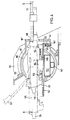
- the roller cover 3 is connected by the bearing 5 so as to be vertically pivotable to a horizontally rotatable tower 21 (not shown).
- two guide elements 17 designed as rods are slidably arranged in two guide bores 36 running in the axis-parallel direction of the firearm 18, which are connected on one side to a slide 16 at the rear end.
- the firearm 18 is connected to the carriage 16 by a releasable bolt 14.
- the slide guide 20 receives two further rods 29 arranged axially parallel to the firearm 18. These rods 29 are equipped with springs 32, 33, which are supported one behind the other on the slide guide 20, for absorbing the recoil and forward forces of the firearm 18, the rods 29 being connected to the slide 16 in the front firing position 19 via two bayonet couplings 28.
- the flap 27 To load the firearm 18, the flap 27 must be opened laterally. In the firing position 19, the flap 27 would abut the belt feed line 8 and the feed line, not shown, of a second barrel weapon 23, for example.
- the firearm 18 can be retracted from a taken index position 25 into a rear position 24 by rotating a mechanism (not shown) by 90 ° .
- the flap for inserting the ammunition belts can be swung open in an opening area 40.
- the tube 31 can be changed by swiveling it down to the tube change position 26, and after the bolt 14 has been removed from the slide 16, the firearm 18 can be pulled completely out of the mount.
- the firearm 18 is mounted in a gas-tight manner in a front attachment 7 in the front area by a ball ring 15 in the firing direction.
- a ball ring 15 is also guided in the rear position 24.
- the diaphragm attachment 7 is screwed onto the roller diaphragm 3 and protrudes from the opening of the diaphragm surface 1, which leaves the diaphragm seal 2 free.
- the roller screen 3 is supported on one side within the tower 21 on the left side in the tower wall 6 by the bearings 5 and the cover plate 12. This enables simple mounting of the roller screen 3 by inserting it into the opening of the screen mounting, so that the screen attachment 7 can then be attached to the roller screen 3.
- the firearm 18 is adjustable on the table 34 due to the displaceability of the slide guide 20 in both directions 35 of the elevation axis 4.
- the firearm 18 is rotated around the bullet ring 15.
- a compensation of a possible oblique position of the firearm 18 with respect to the elevation axis 4 of the roller screen 3 can be achieved by the bolt 14, for example by an adjustable thread.
- the empty cartridge casings can be derived in the shortest possible way directly horizontally from the firearm 18 through the cover plate 12 mounted on the long side in the tower 21 outwards in the direction 11 in front of the slide guide 20.
- a section 38 of the belt ejection channel 13 starting at the firearm 18 is arranged so as to be pivotable away about an axis 39 lying parallel to the weapon.
- the ammunition belts are first guided upwards in the direction 9 through the belt feed line 8 and then into the firearm 18 from above.
- FIGS. 4, 5 and 6 illustrates within a roller cover 103 an arrangement on the right-hand side in the firing direction of an automatic firearm 118, preferably a machine gun, the firearm 118 together with a spring-loaded upper mount 144 on a lower mount connected to the roller cover 103 145, from a front shooting position 119 into a rear position 124 for loading, for changing the barrel and the firearm 118, is retractable.
- the upper mount 144 is connected to the firearm 118 via the bolts 153, 154.
- the roller screen 103 can be swiveled vertically about the elevation axis 104 and is equipped with a screen seal 102 against rainwater and dust, a relatively short screen attachment 107 protruding from the screen surface 101 in the weft direction from the roller screen 103.
- the roller screen 103 is mounted on the right-hand outer tower wall 106 and on the left-hand side on the hood of the tower 121 about the elevation axis 104 in the bearing 105.
- the roller shutter 103 is articulated by a shutter 130, for example a machine gun, mounted in a common roller bearing 105.
- the lower mount 145 essentially consists of two T-rails 147, which are designed as guide elements 117 and are arranged axially parallel to the firearm 118 and are connected to one another via a base plate 150, on which the upper mount 144 is locked in the front firing position 119 by means of a fixation 146.
- the firearm 118 fastened in this way like the firearm 18 (FIG. 1), requires an extremely small swiveling space in the interior of the tower 121 due to the far advanced arrangement within the roller screen 103, 3 (FIG. 1). This arrangement allows the tube to be raised 31 (Fig. 1) and 131 from minus 15 ° to plus 55 °.
- the firearm 118 with the upper mount 144 can be retracted after loosening the fixation 146 in the rear position 124, for inserting the ammunition belts, for changing the barrel 131 and the firearm 118 on the lower mount 145.
- the ammunition belts which can be removed from the belt feed line 108 can be inserted into the firearm 118 when the flap 127 is open at the top, as seen on the left in the firing direction.
- the tube change of the tube 131 can also be carried out on the left side of the firearm 118, as seen in the firing direction, in a manner not shown.
- the firearm 118 In position 124, the firearm 118 can be pulled completely out of the guide of the lower mount 145 with the upper mount 144 to the rear. After a loading process, tube change or weapon change, the firearm 118 is automatically locked in the front firing position 119 by the fixation 146.
- the lower mount 145 is connected to the shortened diaphragm attachment 107 with respect to the elevation axis 104 via a horizontally and vertically adjustable bearing 151.
- the bearing 151 consists of a lower bearing half which is rotatably mounted about a vertical axis 142 in the diaphragm attachment 107 and of an upper bearing half which is fastened to the front end of the lower mount 145 and receives the lower bearing half in a horizontally lying axis 141.
- the advanced installation position of the firearm 118 allows the belt feed line 108 to be arranged on the upper inner edge of the roller cover 103 and a sleeve discharge shaft 110 of the firearm 118 downward into the sleeve discharge shaft 152 of a further tube weapon 123.
- the sleeve discharge shaft 152 passes under the firearm 118, a further shaft 143 of the second pipe also below the sleeve discharge shaft 152 weapon 123 leads through cover plate 112 to the right into the open.
- the belt link ejection channel 113 of the firearm 118 also opens out through the cover plate 112.
- the empty propellant charge cases of the firearm 118 are passed from above through the case discharge shaft 110 passing through the T-rails 147 into the case discharge shaft 152, which runs several times horizontally and at an incline, the case discharge shaft 110 at the junction with the case discharge shaft 152 having a direction of discharge of the empty charge case influencing baffle plate 148 is provided, through which the propellant charge sleeves can be deflected such that they can be ejected directly in the direction 111 through the outlet opening 149 into the open.
- This emission is not affected by an unfavorable position of the vehicle, for example an inclined position.
- the roller cover 103 is pushed into the roller bearing 105 from the right-hand side during assembly and the cover attachment 107 is then screwed on.
Landscapes
- Engineering & Computer Science (AREA)
- General Engineering & Computer Science (AREA)
- Toys (AREA)
- Aiming, Guidance, Guns With A Light Source, Armor, Camouflage, And Targets (AREA)
- Filling Or Emptying Of Bunkers, Hoppers, And Tanks (AREA)
Description
Die Erfindung betrifft eine Turmlafette für automatische Feuerwaffen nach den Merkmalen im Oberbegriff des Patentanspruches 1.The invention relates to a turret mount for automatic firearms according to the features in the preamble of claim 1.
Aus der DE-C-1 124 852 ist gemäß dem Oberbegriff des Anspruches 1 eine Lafettierung von zwei automatischen Feuerwaffen, insbesondere Maschinengewehren bekannt, die in einem Turm eines Panzerwagens gegenüber einer weiteren, mittig angeordneten Rohrwaffe nach hinten versetzt, um die Achsen separat gelagerter Walzenblenden vertikal schwenkbar, an einem jeweiligen Halteteil befestigt sind. Des Halteteil ist mit Kanälen zum seitlichen Ausstoßen der leeren Patronenhülsen und Patronengurtteile ausgerüstet. Für die vertikale Schwenkbewegung ist jedoch innerhalb des Turmes insbesondere bei diesen fest lafettierten Maschinengewehren, ein großer Schwenkbereich erforderlich, weil das hinter der Schwenkachse liegende rückwärtige Ende, bei einer maximalen Rohrerhöhung, tief in den Panzerturm und in den Bereich unterhalb des Turmlagers hineinragt. Dieser Raumbedarf, zum Schwenken der Feuerwaffe im Turm, wird bei Maschinengewehren deshalb benötigt, weil zum Einlegen neuer Munitionsgurte eine aufschwenkbare Klappe, am rückwärtigen Ende zugänglich, geöffnet werden muß. Die Einbaulage des Maschinengewehres in der Blende gestattet darüber hinaus keinen Rohrwechsel ohne Abnahme des Maschinengewehres aus der Halterung bzw. ohne dessen Demontage.From DE-C-1 124 852 is known according to the preamble of claim 1 a mounting of two automatic firearms, in particular machine guns, which in a turret of an armored car is offset to the rear relative to a further, centrally arranged tubular weapon, around the axes of separately mounted roller blinds vertically pivoted, are attached to a respective holding part. The holding part is equipped with channels for laterally ejecting the empty cartridge cases and cartridge belt parts. For the vertical swivel movement, however, a large swivel area is required inside the turret, especially with these fixed-mount machine guns, because the rear end behind the swivel axis, with a maximum pipe elevation, projects deep into the tank turret and into the area below the turret bearing. This space requirement, for swiveling the firearm in the turret, is required for machine guns because a swiveling flap, accessible at the rear end, must be opened to insert new ammunition belts. The installation position of the machine gun in the faceplate also does not allow the barrel to be changed without removing the machine gun from the holder or without disassembling it.
Aus der DE-C-2 126 294 ist eine in einem Geschützturm mittig angeordnete Maschinenkanone mit einer getrennten Hülsen- und Gurtablenkung und einer zusätzlichen Gurtzuführung bekannt, wobei die Maschinenkanone und die Zuführ- und Abführkanäle ebenfalls in einer Walzenblende gelagert sind. In dieser Anordnung ist jedoch die Maschinenkanone ebenfalls fest angeordnet und die Gurtglieder werden über eine relativ lange Ableitstrecke durch profilierte Kanäle vorwiegend waagerecht ins Freie geführt.From DE-C-2 126 294 a machine cannon arranged in the center of a turret with a separate sleeve and belt deflection and an additional belt feeder is known, the machine cannon and the feed and discharge channels also being mounted in a roller screen. In this arrangement, however, the machine cannon is also arranged in a fixed manner and the belt members are mainly led horizontally into the open over a relatively long discharge path through profiled channels.
Weiterhin ist aus der US-A-3 134 302 ein neben der Hauptwaffe blendenlafettiertes Maschinengewehr bekannt. Das hieraus bekannte Maschinengewehr ist jedoch starr neben dem Hauptgeschützrohr eingebaut. Ausschließlich zur Aufnahme der Rückstoßbewegungen ist das Maschinengewehr längsverschieblich in einem Schlitten gelagert, der mit dem Lafettenunterteil verbunden ist. Dieses justierbare Unterteil ist fest an der Wiege des nicht dargestellten Geschützrohres befestigt. Die Längsverschiebbarkeit der Waffe beschränkt sich also lediglich auf den kurzen Federweg der Rückstoß-Dämpfungsfeder. Die bekannte Turmiafette enthält somit neben den längsverschiebbaren Führungsmitteln zur Rückstoßdämpfung keine weiteren Schlitten und Schlittenführungselemente.Furthermore, US-A-3 134 302 discloses a machine gun with a muzzle-coated mount next to the main weapon. The machine gun known from this, however, is rigidly installed next to the main gun barrel. The machine gun is mounted for longitudinal movement in a carriage, which is connected to the lower part of the carriage, only to absorb the recoil movements. This adjustable lower part is firmly attached to the cradle of the gun barrel, not shown. The longitudinal displaceability of the weapon is therefore limited only to the short spring travel of the recoil damping spring. In addition to the longitudinally displaceable guide means for damping recoil, the known turret grease thus contains no further slides and slide guide elements.
In der US-A-2 415 153 wird eine Halterung für eine Feuerwaffe auf der seitlichen Bordwand in der Cockpit-Öffnung eines offenen Kleinflugzeuges offenbart. Hierbei ist im vorderen Bereich der seitlichen Bordwand eine Schiene befestigt, in der ein Sockel oder Tragelement verschiebbar angeordnet ist. Der Sockel trägt drehbar gelagert ein gegabeltes Joch, in dem die Waffe vertikal und lateral kippbar befestigt ist. Diese Waffenlafettierung mit der Funktion einer kardanischen Aufhängung dient einzig und allein dem Zweck, die Waffe bei beliebiger Fluglage des Flugzeuges in eine für den Piloten bzw. Schützen günstige Ziel- bzw. Schießposition zu bringen.US-A-2 415 153 discloses a mount for a firearm on the side wall in the cockpit opening of an open light aircraft. In this case, a rail is fastened in the front area of the side drop side, in which a base or support element is arranged displaceably. The base rotatably supports a forked yoke in which the weapon can be tilted vertically and laterally. This weapon mount with the function of a gimbal serves the sole purpose of bringing the weapon into a target or firing position that is favorable for the pilot or shooter when the aircraft is in any flight position.
Der Erfindung liegt die Aufgabe zugrunde, die Turmlafettierung für automatische Feuerwaffen nach der im Oberbegriff des Patentanspruchs 1 genannten Art dahingehend zu verbessern, daß der zum Schwenken notwendige Raumbedarf wenigstens einer innerhalb einer oder mehrerer um eine gemeinsame Elevationsachse schwenkbaren(r) Walzenblende(n) befestigten automatischen Feuerwaffe, vorzugsweise eines Maschinengewehres, im Turminnern verringert wird, ohne daß die Ableitkanäle für Gurt und Munition oder die Gurtzuleitungen der eigenen oder einer weiteren Rohrwaffe behindert werden und ein Einlegen der Munitionsgurte, ein Rohrwechsel und Ein- und Ausbau der Feuerwaffe innerhalb des Turmes möglich ist.The invention has for its object to improve the turret mount for automatic firearms according to the type mentioned in the preamble of claim 1 in such a way that the space required for pivoting at least one within one or more pivotable roller shutter (s) about a common elevation axis (s) attached automatic firearm, preferably a machine gun, is reduced inside the turret without the discharge channels for belt and ammunition or the belt feed lines of your own or another barrel weapon being obstructed and inserting the ammunition belts, changing the barrel and installing and removing the firearm within the tower is.
Gelöst wird diese Aufgabe durch die im Patentanspruch 1 angegebene Erfindung.This object is achieved by the invention specified in claim 1.
Durch diese Lösung wird aufgrund der weit vorgeschobenen vorderen Schießposition der automatischen Feuerwaffe, in der ausschließlich nur das Schießen erfolgt, nur ein sehr geringer Schwenkradius innerhalb des Turmes benötigt, wodurch der die Feuerwaffe innerhalb der Walzenblende umgebende Raum darüber hinaus optimal für die Zuleitung der Gurte bzw. Ableitkanäle der Treibladungshülsen und Gurtteile einer oder mehrerer auf einer Elevationsachse angeordneter Rohrwaffen ausgenutzt werden kann. Durch die Zurückziehmöglichkeit der Feuerwaffe in einer stets gleichen zum Einlegen der Munitionsgurte, zum Rohrwechsel und zum Ein- und Ausbau der Feuerwaffe vorgesehenen Indexposition wird zusätzlich im Turm Raum für beispielsweise optische Geräte, Höhenrichtgetriebe, das Drehringlager des Turmes etc. geschaffen.Due to the advanced forward firing position of the automatic firearm, in which only firing takes place, this solution means that only a very small swivel radius is required within the turret, which means that the space surrounding the firearm within the roller cover is also optimal for the feed of the belts or Discharge channels of the propellant charge sleeves and belt parts of one or more tubular weapons arranged on an elevation axis can be used. The retractability of the firearm in an index position that is always the same for inserting the ammunition belts, for changing the barrel and for installing and removing the firearm also creates space in the tower for, for example, optical devices, height adjustment gear, the rotating ring bearing of the tower, etc.
Vorteilhafte Ausgestaltungen und Weiterbildungen gehen aus den Unteransprüchen hervor.Advantageous refinements and developments emerge from the subclaims.
Gemäß einer Besonderheit der Erfindung sind die Führungselemente als mit der Feuerwaffe zurückziehbare Stange ausgebildet und in einer blendenfesten Schlittenführung geführt, so daß vor der Schlittenführung ein Hülsenableitschacht direkt auf kürzestem Weg ins Freie führt und unterhalb der Schlittenführung ein teilweise wegschwenkbarer Gurtgliedauswurfkanal durch eine Abdeckplatte ins Freie führt. Dadurch, daß der obere an der Feuerwaffe befindliche Teil des Gurtauswurfkanals wegschwenkbar ist, kann in zurückgezogener Stellung der Feuerwaffe ein Rohrwechsel durch Herabschwenken des Rohres aus der Waffenhalterung durchgeführt werden. Dadurch wird, in Schußrichtung gesehen, rechtsseitig der Feuerwaffe, neben der eigenen Gurtzuleitung, insbesondere Raum für eine weitere parallel zur Waffenrohrachse auf der gleichen Elevationsachse angeordneten Rohrwaffe, beispielsweise eine Maschinenkanone, geschaffen. Durch die Justiermöglichkeit der Schlittenführung und eines am Schlitten formschlüssig befestigten Bolzens kann die Feuerwaffe eine genaue rechtwinklige Lage in Bezug auf die Elevationsachse einnehmen.According to a special feature of the invention, the guide elements are designed as a rod that can be retracted with the firearm and are guided in an anti-glare slide guide, so that a sleeve deflecting duct leads directly to the outside in the shortest possible way before the slide guide and a belt link ejection channel that can be partially swung away leads through a cover plate to the outside below the slide guide . Characterized in that the upper part of the belt ejection channel located on the firearm can be pivoted away, in the retracted position of the firearm it is possible to change the tube by swiveling the tube down be carried out from the weapon holder. As a result, as seen in the firing direction, on the right-hand side of the firearm, in addition to its own belt feed line, in particular space for a further barrel weapon, for example a machine gun, arranged parallel to the barrel axis on the same elevation axis. Due to the possibility of adjusting the slide guide and a bolt that is positively fastened to the slide, the firearm can assume a precise right-angled position with respect to the elevation axis.
Nach einer weiteren Besonderheit sind die Führungselemente als T-Schienen ausgebildet, die als Unterlafette in horizontaler und vertikaler Lage einstellbar mit der Walzenblende verbunden sind. Auf den Führungselementen ist komplett eine mit der Feuerwaffe befestigte und mit Federelementen versehene Oberlafette aus einer Schießposition in eine Lade- bzw. Wechselposition der Feuerwaffe zurückziehbar. Diese Lafettierung gestattet eine feste Anordnung eines nach rechts führenden Gurtgliedauswurfkanals an der Walzenblende und eines nach unten führenden Hülsenableitschachtes an der Unterlafette. Durch die Anordnung eines Prallbleches in dem Hülsenableitschacht ist es möglich, daß die leeren Treibladungshülsen unmittelbar durch die seitliche Abdeckplatte der Walzenblende nach rechts ins Freie gelangen und der Hülsenableitschacht gleichzeitig in abgekröpfter Anordnung als unter der Feuerwaffe hindurchgehender Hülsenableitschacht einer linksseitig parallel zur Feuerwaffe auf der gleichen Elevationsachse angeordneten weiteren Rohrwaffe raumsparend eingesetz werden kann. Die Anordnung einer jeweils mit einer eigenen Walzenblende ausgerüsteten, vertikal schwenkbaren Feuerwaffe auf der Elevationsachse einer weiteren Rohrwaffe, gestattet vorteilhaft die Möglichkeit einer unmittelbaren Anlenkung der Blende der ersten Feuerwaffe durch die Blende der zweiten Rohrwaffe.According to a further special feature, the guide elements are designed as T-rails, which are adjustably connected to the roller screen as a lower mount in a horizontal and vertical position. On the guide elements, an upper mount, which is fastened with the firearm and provided with spring elements, can be withdrawn from a firing position into a loading or changing position of the firearm. This mounting allows a fixed arrangement of a belt link ejection channel leading to the right on the roller cover and a downward sleeve discharge shaft on the lower mount. The arrangement of a baffle in the sleeve discharge chute makes it possible for the empty propellant charge sleeves to pass directly to the outside through the side cover plate of the roller screen and the sleeve discharge chute at the same time in a cranked arrangement as a sleeve discharge chute passing under the firearm on the left parallel to the firearm on the same elevation axis arranged further barrel weapon can be used to save space. The arrangement of a vertically pivotable firearm, each equipped with its own roller blind, on the elevation axis of a further tube weapon advantageously allows the possibility of direct articulation of the aperture of the first firearm through the aperture of the second tube weapon.
Die Erfindung wird nachstehend anhand der in den Zeichnungen unter weitgehendem Verzicht auf erfindungsunwesentliche Einzelheiten dargestellten bevorzugten Ausführungsbeispiele näher erläutert.The invention is explained in more detail below with reference to the preferred exemplary embodiments shown in the drawings, largely without the details that are not essential to the invention.
Es zeigt :
- Fig. 1 in einer Schnittdarstellung entlang der in Fig. 2 gekennzeichneten Linie I-I ein linksseitig in einer Walzenblende gelagertes Maschinengewehr ;
- Fig. 2 in einem Halbschnitt entlang der in Fig. 1 angegebenen Linie 11-11 das gleiche Maschinengewehr mit Anordnung der Lafettierung und Lagerung an der linken Außenwand der Walzenblende ;
- Fig. 3 in einer Schnittdarstellung entlang der in Fig. 2 gekennzeichneten Linie 111-111 die Befestigung der Lafettierung an der Walzenblende sowie den Gurtzuführ- und Auswurfkanal und den Hülsenablenkschacht ;
- Fig. 4 in einer Schnittdarstellung entlang der Linie IV-IV der
Figur 5 ein auf einer feststehenden Unterlafette angeordnetes zurückziehbares Maschinengewehr ; - Fig. 5 im Halbschnitt entlang der in Fig. 4 gekennzeichneten Linie V-V das Maschinengewehr mit Lagerungen der Walzenblende im Turm sowie die Anordnung des Gurtgliedzuführ- und Auswurfkanals ;
- Fig. 6 in einer Schnittdarstellung entlang der in
Figur 5 gekennzeichneten Linie VI-VI neben der eigenen die Anordnung eines Hüisenableitschachtes und eines Gurtgliedauswurfkanals einer weiteren Rohrwaffe.
- 1 shows a sectional view along the line II marked in FIG. 2, a machine gun mounted on the left in a roller screen;
- Fig. 2 in a half section along the line 11-11 shown in Figure 1, the same machine gun with arrangement of the mount and storage on the left outer wall of the roller blind.
- Fig. 3 in a sectional view along the line 111-111 marked in Fig. 2, the attachment of the mount to the roller cover as well as the belt feed and ejection channel and the sleeve deflection shaft;
- 4 shows a sectional view along the line IV-IV of FIG. 5, a retractable machine gun arranged on a fixed lower mount;
- . Fig. 5 taken along line VV in Figure 4 is marked in half section the machine gun with bearings of the roll shutter in the tower as well as the arrangement of the Gurtgliedzuführ- and Auswur f channel;
- Fig. 6 in a sectional view along the line VI-VI marked in Figure 5 in addition to its own the arrangement of a Hüisenablitschachtes and a belt member ejection channel of another gun.
Bei der in den Figuren 1 bis 3 dargestellten Ausführungsform ist eine automatische Feuerwaffe 18, vorzugsweise ein Maschinengewehr, linksseitig in Schußrichtung gesehen, innerhalb einer Walzenblende 3 lafettiert. Die Walzenblende 3 ist durch die Lagerung 5 vertikal schwenkbar mit einem nicht weiter dargestellten horizontal drehbaren Turm 21 verbunden. Innerhalb der Walzenblende 3 ist ein fest mit ihr verbundener Tisch 34 angeordnet, auf dem zur Justierung in seitlicher Richtung 35 verschiebbar eine Schlittenführung 20 über bekannte Befestigungsmittel 37 angeschlossen ist. In der Schlittenführung 20 sind in zwei in achsparalleler Richtung der Feuerwaffe 18 verlaufenden Führungsbohrungen 36 zwei als Stangen ausgebildete Führungselemente 17 verschiebbar angeordnet, die einseitig am hinteren Ende mit einem Schlitten 16 verbunden sind. Durch einen lösbaren Bolzen 14 ist die Feuerwaffe 18 mit dem Schlitten 16 verbunden. Die Schlittenführung 20 nimmt zwei weitere achsparallel zur Feuerwaffe 18 angeordnete Stangen 29 auf. Diese Stangen 29 sind mit hintereinander sich entgegengesetzt an der Schlittenführung 20 abstützenden Federn 32, 33 zur Aufnahme der Rückstoß-und Vorlaufkräfte der Feuerwaffe 18 ausgerüstet, wobei die Stangen 29 in der vorderen Schußposition 19 über zwei Bajonettkupplungen 28 mit dem Schlitten 16 verbunden sind.In the embodiment shown in FIGS. 1 to 3, an
Zum Beladen der Feuerwaffe 18 muß die Klappe 27 seitlich geöffnet werden. In Schußposition 19 würde die Klappe 27 gegen die Gurtzuleitung 8 und gegen die nicht dargestellte Zuleitung einer beispielsweise zweiten Rohrwaffe 23 stoßen. Um dennoch die Feuerwaffe 18 einwandfrei laden zu können, ist nach Lösen der formschlüssig mit dem Schlitten 16 verbundenen Bajonettkupplung 28, durch Drehung eines nicht näher dargestellten Mechanismus um 90°, die Feuerwaffe 18, aus einer eingenommenen Indexposition 25, in eine hintere Position 24 zurückziehbar. In dieser Position 24 ist die Klappe zum Einlegen der Munitionsgurte in einem Öffnungsbereich 40 aufschwenkbar. In dieser Position 24 kann ein Wechsel des Rohres 31 durch Herunterschwenken in Rohrwechselposition 26 erfolgen, und nach Herausnahme des Bolzens 14 aus dem Schlitten 16 ist die Feuerwaffe 18 ganz aus der Lafettierung herausziehbar.To load the
Neben der Halterung 14 ist die Feuerwaffe 18 im vorderen Bereich durch einen Kugelring 15 in Schußrichtung frei beweglich in einem Blendenvorsatz 7 gasdicht gelagert. Durch innerhalb des Blendenvorsatzes 7 angeordnete Führungen 22 ist der Kugelring 15 auch in der hinteren Position 24 geführt. Der Blendenvorsatz 7 ist an der Walzenblende 3 angeschraubt und ragt aus der Öffnung der Blendenoberfläche 1, die die Blendenabdichtung 2 frei läßt, heraus. Die Walzenblende 3 ist innerhalb des Turmes 21 auf der linken Seite in der Turmwand 6 durch die Lager 5 und die Abdeckplatte 12 einseitig abgestützt gelagert. Dadurch ist eine einfache Montage der Walzenblende 3 durch Einschub in die Öffnung der Blendenlagerung möglich, so daß der Blendenvorsatz 7 anschließend an der Walzenblende 3 befestigt werden kann. Die Feuerwaffe 18 ist durch die Verschiebbarkeit der Schlittenführung 20 in beide Richtungen 35 der Elevationsachse 4 auf dem Tisch 34 justierbar. Die Feuerwaffe 18 wird dabei um den Kugelring 15 gedreht. Ein Ausgleich einer eventuellen Schräglage der Feuerwaffe 18 gegenüber der Elevationsachse 4 der Walzenblende 3 kann durch den Bolzen 14 erreicht werden, beispielsweise durch ein justierbares Gewinde.In addition to the
Die Justierung einer gleichen Stellung der Feuerwaffe 18 auf der Elevationsachse 4 gegenüber einer zweiten Rohrwaffe 23, ist in einer nicht näher dargestellten Form durch die Anlenkung der Blende 30, z. B. von einer Maschinenkanone, möglich.The adjustment of the same position of the
Innerhalb der Walzenblende 3 sind vor der Schlittenführung 20 die leeren Patronenhülsen über die Hülsenableitung 10 auf kürzestem Weg direkt horizontal von der Feuerwaffe 18 durch die im Turm 21 längsseitig gelagerte Abdeckplatte 12 hindurch nach außen in Richtung 11 ableitbar.Within the
Damit der Rückziehvorgang der Feuerwaffe 18 nicht durch den unterhalb der Feuerwaffe 18 : befindlichen Gurtgliedauswurfkanal 13 behindert wird, ist ein an der Feuerwaffe 18 beginnender Abschnitt 38 des Gurtauswurfkanals 13 um eine waffenachsparallel liegende Achse 39 wegschwenkbar angeordnet. In vorderer Schießposition 19 werden die Munitionsgurte zunächst in Richtung 9 durch die Gurtzuleitung 8 nach oben und dann von obenher in die Feuerwaffe 18 geleitet.So that the retraction process of the
Die in den Figuren 4, 5 und 6 dargestellte Ausführungsform verdeutlicht innerhalb einer Walzenblende 103 eine rechtsseitige in Schußrichtung gesehene Anordnung einer automatischen Feuerwaffe 118, vorzugsweise eines Maschinengewehrs, wobei die Feuerwaffe 118 gemeinsam mit einer gefederten Oberlafette 144, auf einer mit der Walzenblende 103 verbundenen Unterlafette 145, aus einer vorderen Schießposition 119 in eine hintere Position 124 zum Laden, zum Wechsel des Rohres und der Feuerwaffe 118, zurückziehbar ist. Die Oberlafette 144 ist dabei über die Bolzen 153, 154 mit der Feuerwaffe 118 verbunden.The embodiment shown in FIGS. 4, 5 and 6 illustrates within a
Die Walzenblende 103 ist ähnlich der Walzenblende 3 (Fig. 1) um die Elevationsachse 104 vertikal schwenkbar und ist gegen Regenwasser und Staub mit einer Blendenabdichtung 102 ausgerüstet, wobei aus der Blendenoberfläche 101 ein verhältnismäßig kurzer Blendenvorsatz 107 in Schußrichtung aus der Walzenblende 103 herausragt. Die Walzenblende 103 ist an der rechtsseitigen äußeren Turmwand 106 und linksseitig an der Haube des Turmes 121 schwenkbar um die Elevationsachse 104 in der Lagerung 105 gelagert. Bei der Anordnung einer weiteren automatischen Rohrwaffe 123 wird die Walzenblende 103 von einer in einer gemeinsamen Rollenlagerung 105 gelagerten Blende 130, beispielsweise einer Maschinenkanone, angelenkt.The
Die Unterlafette 145 besteht im wesentlichen aus zwei als Führungselemente 117 ausgebildeten achsparallel zur Feuerwaffe 118 angeordneten und über eine Grundplatte 150 miteinander verbundenen T-Schienen 147, auf welchen in der vorderen Schießposition 119 die Oberlafette 144 über eine Fixierung 146 arretiert ist. Die derartig befestigte Feuerwaffe 118 benötigt, wie die Feuerwaffe 18 (Fig. 1), aufgrund der weit vorgeschobenen Anordnung innerhalb der Walzenblende 103, 3 (Fig. 1) einen äußerst kleinen Schwenkraum im Innenraum des Turmes 121. Diese Anordnung gestattet eine Erhöhung des Rohres 31 (Fig. 1) und 131 von minus 15° bis plus 55°.The
In der Indexstellung 125 ist die Feuerwaffe 118 mit der Oberlafette 144 nach Lösen der Fixierung 146 in die rückwärtige Position 124, zum Einlegen der Munitionsgurte, zum Wechsel des Rohres 131 und der Feuerwaffe 118 auf der Unterlafette 145 zurückziehbar. Die aus der Gurtzuleitung 108 entnehmbaren Munitionsgurte sind bei nach oben geöffneter Klappe 127, linksseitig in Schußrichtung gesehen, in die Feuerwaffe 118 einlegbar. Der Rohrwechsel des Rohres 131 kann ebenfalls in Schußrichtung gesehen auf der linken Seite der Feuerwaffe 118 in einer nicht dargestellten Weise durchgeführt werden. In der Position 124 kann die Feuerwaffe 118 komplett mit der Oberlafette 144 nach hinten aus der Führung der Unterlafette 145 herausgezogen werden. Nach einem Ladevorgang, Rohrwechsel oder Waffenwechsel wird die Feuerwaffe 118 in der vorderen Schießposition 119 durch die Fixierung 146 selbsttätig verriegelt.In
Zum Justieren ist die Unterlafette 145 gegenüber der Elevationsachse 104 über ein horizontal und vertikal einstellbares Lager 151 mit dem verkürzten Blendenvorsatz 107 verbunden. Das Lager 151 besteht aus einer um eine senkrechte Achse 142 im Blendenvorsatz 107 drehbar gelagerten unteren Lagerhälfte und aus einer am vorderen Ende der Unterlafette 145 befestigten, die untere Lagerhälfte in einer horizontal liegenden Achse 141 aufnehmenden oberen Lagerhälfte.For adjustment, the
Die vorgezogene Einbaulage der Feuerwaffe 118 gestattet eine Anordnung der Gurtzuleitung 108 an der oberen Innenkante der Walzenblende 103 und ein Hülsenableitschacht 110 der Feuerwaffe 118 nach unten in den Hülsenableitschacht 152 einer weiteren Rohrwaffe 123. Bei dieser Lafettierung führt der Hülsenableitschacht 152 unter der Feuerwaffe 118 hindurch, wobei unterhalb des Hülsenableitschachtes 152 ebenfalls noch ein weiterer Schacht 143 der zweiten Rohrwaffe 123 durch die Abdeckplatte 112 hindurch nach rechts ins Freie führt. Oberhalb des Hülsenableitschachtes 152 mündet durch die Abdeckplatte 112 hindurch der Gurtgliedauswurfkanal 113 der Feuerwaffe 118 ebenfalls nach außen. Die leeren Treibladungshülsen der Feuerwaffe 118 werden durch den zwischen den T-Schienen 147 hindurchgehenden Hülsenableitschacht 110 von oben her in den mehrfach horizontal und schräggeneigt verlaufenden Hülsenableitschacht 152 geleitet, wobei der Hülsenableitschacht 110 an der Einmündung in den Hülsenableitschacht 152 mit einem die Ableitrichtung der leeren Treibladungshülsen beeinflussenden Prallblech 148 versehen ist, durch das die Treibladungshülsen derartig ablenkbar sind, daß sie direkt in Richtung 111 durch die Austrittsöffnung 149 ins Freie ausstoßbar sind. Dieser Ausstoß wird auch nicht durch eine ungünstige Stellung des Fahrzeuges, beispielsweise eine Schräglage, beeinträchtigt.The advanced installation position of the
Ebenso vorteilhaft wie die linksseitige Montage der Walzenblende 3 (Fig. 1), wird die Walzenblende 103 bei der Montage von der rechten Seite in die Rollenlager 105 eingeschoben und der Blendenvorsatz 107 anschließend verschraubt.Just as advantageous as the left-hand assembly of the roller cover 3 (FIG. 1), the
Claims (10)
Applications Claiming Priority (2)
| Application Number | Priority Date | Filing Date | Title |
|---|---|---|---|
| DE3325924 | 1983-07-19 | ||
| DE19833325924 DE3325924A1 (en) | 1983-07-19 | 1983-07-19 | DIRECTIONAL FASTENING AT LEAST ONE AUTOMATIC TUBE ARM IN CONFINED INSTALLATION |
Publications (3)
| Publication Number | Publication Date |
|---|---|
| EP0141018A2 EP0141018A2 (en) | 1985-05-15 |
| EP0141018A3 EP0141018A3 (en) | 1986-02-05 |
| EP0141018B1 true EP0141018B1 (en) | 1988-01-20 |
Family
ID=6204302
Family Applications (1)
| Application Number | Title | Priority Date | Filing Date |
|---|---|---|---|
| EP84106798A Expired EP0141018B1 (en) | 1983-07-19 | 1984-06-14 | Turret mounting for an automatic gun |
Country Status (3)
| Country | Link |
|---|---|
| EP (1) | EP0141018B1 (en) |
| DE (2) | DE3325924A1 (en) |
| ES (1) | ES534418A0 (en) |
Cited By (1)
| Publication number | Priority date | Publication date | Assignee | Title |
|---|---|---|---|---|
| KR101244795B1 (en) * | 2008-07-23 | 2013-03-18 | 마이크로 모우션, 인코포레이티드 | Processing system with external memory access control |
Families Citing this family (3)
| Publication number | Priority date | Publication date | Assignee | Title |
|---|---|---|---|---|
| FR2835048B1 (en) * | 2002-01-22 | 2006-06-16 | Giat Ind Sa | TURRET FOR MILITARY VEHICLE |
| IL225229A (en) | 2013-03-14 | 2016-12-29 | Rafael Advanced Defense Systems Ltd | Spent cartridges router |
| US9328986B1 (en) | 2014-11-04 | 2016-05-03 | Oshkosh Corporation | Turret assembly |
Family Cites Families (11)
| Publication number | Priority date | Publication date | Assignee | Title |
|---|---|---|---|---|
| DE674344C (en) * | 1933-08-15 | 1939-03-29 | Berlin Suhler Waffen Und Fahrz | Return device for machine guns |
| US2415153A (en) * | 1934-05-01 | 1947-02-04 | Curtiss Aeroplane & Motor Co | Mount and spent ammunition retriever for flexibly mounted guns |
| US2243365A (en) * | 1939-11-24 | 1941-05-27 | Bell Aircraft Corp | Mounting device for machine guns |
| US2601457A (en) * | 1944-11-22 | 1952-06-24 | United Aircraft Corp | Gun adapter |
| GB786492A (en) * | 1954-08-24 | 1957-11-20 | Gloster Aircraft Company Ltd | Improvements in or relating to gun mountings |
| FR1277826A (en) * | 1960-01-20 | 1961-12-01 | Rheinmetall Gmbh | Ball head for automatic firearms |
| BE625709A (en) * | 1961-12-05 | |||
| US3854377A (en) * | 1972-05-20 | 1974-12-17 | Keller & Knappich Augsburg | Tank turret for automatic weapons |
| FR2198620A5 (en) * | 1972-09-06 | 1974-03-29 | Creusot Loire | |
| FR2371664A1 (en) * | 1976-11-19 | 1978-06-16 | Alsetex | Grenade launcher mounted on armoured vehicle - has rifle mounted in sleeve by swivelling joints and withdrawable inwards for loading |
| DE3150250A1 (en) * | 1981-12-18 | 1983-06-30 | INA Wälzlager Schaeffler KG, 8522 Herzogenaurach | ROLLER BEARING FOR THE SLIDING GUIDE OF A BULLET PIPE |
-
1983
- 1983-07-19 DE DE19833325924 patent/DE3325924A1/en not_active Withdrawn
-
1984
- 1984-06-14 DE DE8484106798T patent/DE3468940D1/en not_active Expired
- 1984-06-14 EP EP84106798A patent/EP0141018B1/en not_active Expired
- 1984-07-18 ES ES534418A patent/ES534418A0/en active Granted
Cited By (1)
| Publication number | Priority date | Publication date | Assignee | Title |
|---|---|---|---|---|
| KR101244795B1 (en) * | 2008-07-23 | 2013-03-18 | 마이크로 모우션, 인코포레이티드 | Processing system with external memory access control |
Also Published As
| Publication number | Publication date |
|---|---|
| ES8505100A1 (en) | 1985-05-01 |
| ES534418A0 (en) | 1985-05-01 |
| DE3325924A1 (en) | 1985-01-31 |
| EP0141018A3 (en) | 1986-02-05 |
| EP0141018A2 (en) | 1985-05-15 |
| DE3468940D1 (en) | 1988-02-25 |
Similar Documents
| Publication | Publication Date | Title |
|---|---|---|
| EP1061323B1 (en) | Armoured vehicle for the transport of soldiers | |
| DE2826136C3 (en) | Device for the transport of ammunition from an armored vehicle to a top-mounted gun fixed on a platform | |
| DE10258263B4 (en) | firing module | |
| DE3041866A1 (en) | DEVICE FOR TRANSPORTING AMMUNITION FROM AN AMMUNITION CONTAINER TO THE CLOSURE DEVICE OF A WEAPON | |
| EP0557751B1 (en) | Howitzer with pivotable loading arm and ammunition magazine of the endless-chain type | |
| EP0141018B1 (en) | Turret mounting for an automatic gun | |
| EP2494302B1 (en) | Catch device for ammunition casings and/or belt links | |
| DE3022410C2 (en) | Device for feeding projectile ammunition in an armored vehicle | |
| DE2501424A1 (en) | AMMUNITION HOLDER AND LOADING DEVICE FOR A LARGE-CALIBER FIREARM | |
| EP0011856B1 (en) | Device for locking a carrier which is rotatable about a horizontal axis and which supports a weapon, e.g. a quick-firing gun, which can be directed in elevation | |
| DE3701713C2 (en) | ||
| EP0640805A1 (en) | Ammunition feeding device for a cannon of an armoured vehicle | |
| EP1557634A1 (en) | Device for supporting a weapons platform | |
| DE19648348A1 (en) | Rifle chariots | |
| EP0428825A2 (en) | Loading tray for a muzzle loaded mortar | |
| DE1268023B (en) | Dense hollow drum as a support member of an automatic firearm in an armored turret of an armored vehicle | |
| EP0635695B1 (en) | Fighting vehicle, in particular howitzer, with ammunition magazines | |
| DE102004063882B4 (en) | Device for holding a weapon station | |
| EP0221935A1 (en) | Device for transferring ammunition cartridges from a container magazine to a turret magazine. | |
| EP4370859A1 (en) | Feeding device for loading and unloading a radially opening ammunition cup for an automatic loading system of a gun | |
| DE2852699C1 (en) | Device for the supply of ammunition from a magazine located below a rotatable platform to a crest gun mounted on the platform | |
| DE2543155B2 (en) | Large caliber weapon for high and low fire | |
| EP0491271A1 (en) | Weapon system with four barrels | |
| DE3124728A1 (en) | "DEVICE FOR PROMOTING AND LOADING LARGE-CALIBRATED, CARTRIDGED AMMUNITION" | |
| DE102024108024A1 (en) | Primer magazine changing device with swivel arm |
Legal Events
| Date | Code | Title | Description |
|---|---|---|---|
| PUAI | Public reference made under article 153(3) epc to a published international application that has entered the european phase |
Free format text: ORIGINAL CODE: 0009012 |
|
| AK | Designated contracting states |
Designated state(s): CH DE IT LI |
|
| PUAL | Search report despatched |
Free format text: ORIGINAL CODE: 0009013 |
|
| AK | Designated contracting states |
Designated state(s): CH DE IT LI |
|
| 17P | Request for examination filed |
Effective date: 19851211 |
|
| 17Q | First examination report despatched |
Effective date: 19860829 |
|
| D17Q | First examination report despatched (deleted) | ||
| ITF | It: translation for a ep patent filed | ||
| GRAA | (expected) grant |
Free format text: ORIGINAL CODE: 0009210 |
|
| AK | Designated contracting states |
Kind code of ref document: B1 Designated state(s): CH DE IT LI |
|
| REF | Corresponds to: |
Ref document number: 3468940 Country of ref document: DE Date of ref document: 19880225 |
|
| PLBE | No opposition filed within time limit |
Free format text: ORIGINAL CODE: 0009261 |
|
| STAA | Information on the status of an ep patent application or granted ep patent |
Free format text: STATUS: NO OPPOSITION FILED WITHIN TIME LIMIT |
|
| 26N | No opposition filed | ||
| ITTA | It: last paid annual fee | ||
| PGFP | Annual fee paid to national office [announced via postgrant information from national office to epo] |
Ref country code: CH Payment date: 19970522 Year of fee payment: 14 |
|
| PGFP | Annual fee paid to national office [announced via postgrant information from national office to epo] |
Ref country code: DE Payment date: 19970530 Year of fee payment: 14 |
|
| PG25 | Lapsed in a contracting state [announced via postgrant information from national office to epo] |
Ref country code: LI Free format text: LAPSE BECAUSE OF NON-PAYMENT OF DUE FEES Effective date: 19980630 Ref country code: CH Free format text: LAPSE BECAUSE OF NON-PAYMENT OF DUE FEES Effective date: 19980630 |
|
| REG | Reference to a national code |
Ref country code: CH Ref legal event code: PL |
|
| PG25 | Lapsed in a contracting state [announced via postgrant information from national office to epo] |
Ref country code: DE Free format text: LAPSE BECAUSE OF NON-PAYMENT OF DUE FEES Effective date: 19990401 |