EP0140511B1 - Method and apparatus for removing excess material from sand cores - Google Patents
Method and apparatus for removing excess material from sand cores Download PDFInfo
- Publication number
- EP0140511B1 EP0140511B1 EP19840305627 EP84305627A EP0140511B1 EP 0140511 B1 EP0140511 B1 EP 0140511B1 EP 19840305627 EP19840305627 EP 19840305627 EP 84305627 A EP84305627 A EP 84305627A EP 0140511 B1 EP0140511 B1 EP 0140511B1
- Authority
- EP
- European Patent Office
- Prior art keywords
- particles
- cores
- conduit
- stream
- nozzle
- Prior art date
- Legal status (The legal status is an assumption and is not a legal conclusion. Google has not performed a legal analysis and makes no representation as to the accuracy of the status listed.)
- Expired
Links
Images


Classifications
-
- B—PERFORMING OPERATIONS; TRANSPORTING
- B22—CASTING; POWDER METALLURGY
- B22C—FOUNDRY MOULDING
- B22C9/00—Moulds or cores; Moulding processes
- B22C9/18—Finishing
Landscapes
- Engineering & Computer Science (AREA)
- Mechanical Engineering (AREA)
- Cleaning In General (AREA)
- Injection Moulding Of Plastics Or The Like (AREA)
- Casting Devices For Molds (AREA)
Description
- This invention relates generally to apparatus for finishing and cleaning molded articles by directing particulate material against the rough moulded article. Impeller systems for directing metal shot against cast metal articles for cleaning the articles are well known.
- The present invention relates more specifically to the finish cleaning of molded sand cores which are made by molding a mixture of sand and a binder, to form a core that may be of complex shape having holes, projections, notches, and other irregularly shaped areas. Such articles are far more delicate than the articles which have heretofore been finished by blasting with an impact media, often metal particles moving at high velocities. Accordingly, prior art blasting apparatus and methods have not been adaptable to the problem of automated cleaning of molded sand cores, and the present rubbing by hand methods for cleaning cores are unacceptable because they are time consuming and expensive.
- It is an object of the present invention, therefore, to provide an improved method and apparatus for removing flash and other excess material from said cores by directing a fluidized media of impact particles against the sand cores.
- US-A-2929120 discloses apparatus for removing flash and other excess material from sand cores in accordance with the prior art portion of claim 1. This prior apparatus uses particles of sand carried in a stream of air to engage the sand cores to be cleaned and finished. As compared therewith the present invention, as characterised in the characterising portion of claim 1, uses a stream containing a large volume of relatively soft cleaning particles which have a gentle but effective cleaning action on the lightweight sand cores. The particular entraining means of the present invention enables a relatively high volume of the soft cleaning particles to be entrained in the relatively low pressure stream of conveying air so as to provide the necessary gentle cleaning action on the lightweight sand cores.
- Thus relatively soft impact particles are showered against the cores in a relatively gentle manner so as to remove flash and other excess material without damaging the cores. The preferred apparatus consists of a conveyor on which the relatively light-weight sand cores are supported so that the opposite sides of the cores can be reached by streams of impact particles. A plurality of nozzles are positioned both above and below the conveyor and relatively low pressure air is directed through the nozzles in the direction of the sand cores on the conveyors. Large volumes of relatively soft impact particles without any sharp points or edges, such as small pieces of plastic, are entrained in the air so that they will be directed against the sand cores. The flash and other excess material is relatively loosely adhered or attached to the main body of the core and as a result, when these loosely adhered pieces are impacted by the moving particles, they are dislodged from the main body of the core. However, when these relatively soft slow moving particles engage the sand core, the particles do not damage or disrupt the surface of the main body of the core.
- Accordingly, when the sand cores that are on the moving conveyor are exposed to the action of the fluidized impact media for a relatively short time, the flash and other excess-material is quickly removed from the cores. As a result, the apparatus can be operated continuously to automatically clean and finish a large number of sand cores in a short time.
- The use of the apparatus of this invention is advantageous in that it provides for the rapid and thorough cleaning of complex parts by subjecting these parts to showers of particles moving against the parts from different directions so as to finish both internal and external surfaces in the part.
- Further objects, features and advantages of this invention will become apparent from a consideration of the following description and the appended claims, when taken in connection with the accompanying drawings in which:
- Fig. 1 is an end view of the core de-finning apparatus of this invention;
- Fig. 2 is a reduced side elevational view of the apparatus of this invention, with some parts broken away for the purpose of clarity;
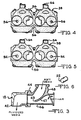
- Fig. 3 is a sectional view of one of the nozzles in the apparatus of this invention;
- Fig. 4 is a fragmentary top view of a sand core prior to cleaning;
- Fig. 5 is a top view of the sand core shown in Fig. 4, after cleaning; and
- Fig. 6 is a perspective view of an impact particle useable in the method and apparatus of this invention.
- With reference to the drawing, the apparatus of this invention, indicated generally at 10, is shown in Figs. 1 and 2 as including a main frame 12 on which is mounted a
housing 14 and aconveyor assembly 16 which is operable to move sand cores to be cleaned through thehousing 14. A piuratity ofnozzles 18 are mounted in thehousing 14 at positions above theconveyor assembly 16 and a plurality of thesame nozzles 18 mounted below theconveyor 16. Thenozzles 18 are supplied with air by a blower orturbine 20 and aparticalized media 22 is fed to thenozzles 18 from asupply hopper 24 located above thenozzles 18. Anelevator assembly 26, of conventional type, operates to transfer usedparticles 22 from the bottom of the apparatus and deliver these particles to thehopper 24 for re-use. - The
conveyor assembly 16 is illustrated as including a plurality of endless strands 28 (Fig. 1), similar to ropes or cables, trained about pulley orsheave assemblies pulley assembly 30 includes a shaft 34 which is driven by amotor drive assembly 36 so as to move thestrands 28 that extend horizontally between thepulley assemblies horizontal strands 28 and are moved by the strands into thehousing 14 to positions between the upwardly and downwardly directed nozzles assemblies 18. During movement of thecores 38 into and out of thehousing 14, they move throughrubber curtains 40 which tend to confine theparticles 22 from thenozzles 18 to thehousing 14. - As shown in Fig. 3, each of the
nozzles 18 consists of a nozzle head 42 rotatably mounted on aninjector body 44 which is connected to aconduit 46 through which air is supplied from theblower 20 and aconduit 48 through which theparticles 22 are supplied. - An
inclined septum 47 directs the particles inconduit 48 toward the air stream emanating fromconduit 46 at thelower edge 49 of theseptum 47. Since the air stream inconduit 46 is created by theblower 20, in contrast to a compressor, it is at a low superatmospheric pressure, namely, below 2 psi. (0.14 bore). As a result, the stream entrains large volumes of theparticles 22 falling off theedge 49 in the form of a curtain. This forms a low pressure stream issuing from nozzle head 42 that contains a dense accumulation ofparticles 22 directed toward sand cores to be cleaned. It is to be understood that the nozzle head 42 can be remote from the injector--body 44 and be connected thereto by a suitable passage. - The result is a relatively soft flow of
particles 22 from each nozzle head 42 that provides for a shower of theparticles 22 on both the top and bottom sides of thecores 38 supported on thestrands 28 in thehousing 14. A variety of different relativelysoft particles 22 that do not have sharp edges or corners, such as walnut shells, corn cobs and similar non-ferrous media, can be used inapparatus 10. Particles that are as hard as conventional steel shot used for blast cleaning are too hard and cause erosion of a sand core. However,particles 22 formed of plastic and generally cylindrical in shape and processed so as to have rounded edges, as illustrated in Fig. 6, are preferred from the standpoints of effectiveness, cost, cleanliness and lack of surface erosion on the core. - The
particles 22 are preferably formed of an easily obtained plastic, such as polyethylene or polypropylene, and are relatively small .in size, having a diameter of about 0.07 inches (1.8 mm) and a length of about 0.10 inches (2.54 mm) or less. - A rough molded
sand core 38 is shown in Fig. 4. The core is of a relatively complex shape having notches 50,openings 52,projections 54, and other irregularly shaped surfaces on which excess material, a mixture of sand and the binder, adhere as indicated at 56. These excess adheringportions 56 are sometimes referred to as "flash" and must be removed from the main body 58 of thesand core 38 in order to make thecore 38 useable for its intended purpose in a molding process. - As shown in Fig. 5, when the
core 38 has been subjected to the action of theapparatus 10, all of theexcess material 56 has been removed so that thecore 38 can now be used without further processing. In the operation of theapparatus 10, thecores 38 are placed on theconveyor 16 as shown in Fig. 2 so that they travel on theconveyor 16 through theenclosure 14 and are subjected to the fluidizedmedia 22 that is directed from both above and below onto the surfaces of thesand core 38. The open construction of theconveyor 16 enables thorough showering of thecore 38 from both above and below. After thesand cores 38 emerge from thehousing 14, they are readily useable in molding operations. - From the above description, it is seen that the method and apparatus of this invention provides for the relatively gentle application of soft impact particles against the somewhat vulnerable body 58 of the
sand core 38 so as to provide for the complete removal of all of theexcess materials 56 on the body 58 without danger of damage to the body 58.
Claims (7)
Applications Claiming Priority (2)
| Application Number | Priority Date | Filing Date | Title |
|---|---|---|---|
| US52926083A | 1983-09-06 | 1983-09-06 | |
| US529260 | 1983-09-06 |
Publications (2)
| Publication Number | Publication Date |
|---|---|
| EP0140511A1 EP0140511A1 (en) | 1985-05-08 |
| EP0140511B1 true EP0140511B1 (en) | 1987-11-04 |
Family
ID=24109161
Family Applications (1)
| Application Number | Title | Priority Date | Filing Date |
|---|---|---|---|
| EP19840305627 Expired EP0140511B1 (en) | 1983-09-06 | 1984-08-17 | Method and apparatus for removing excess material from sand cores |
Country Status (5)
| Country | Link |
|---|---|
| EP (1) | EP0140511B1 (en) |
| JP (1) | JPS6072638A (en) |
| AU (1) | AU574382B2 (en) |
| CA (1) | CA1214916A (en) |
| DE (1) | DE3467105D1 (en) |
Cited By (1)
| Publication number | Priority date | Publication date | Assignee | Title |
|---|---|---|---|---|
| DE10225666B4 (en) * | 2001-06-11 | 2004-10-28 | General Motors Corp., Detroit | Casting engine blocks |
Families Citing this family (3)
| Publication number | Priority date | Publication date | Assignee | Title |
|---|---|---|---|---|
| DE102016114826A1 (en) * | 2016-08-10 | 2018-02-15 | Knorr-Bremse Systeme für Nutzfahrzeuge GmbH | brake carrier |
| WO2019051521A1 (en) * | 2017-09-18 | 2019-03-21 | Fill Gesellschaft M.B.H. | Method for deburring casting cores and casting moulds |
| AT522989B1 (en) * | 2019-10-03 | 2021-12-15 | Fill Gmbh | surface treatment process |
Family Cites Families (5)
| Publication number | Priority date | Publication date | Assignee | Title |
|---|---|---|---|---|
| US2929120A (en) * | 1957-12-04 | 1960-03-22 | Gen Motors Corp | Method of definning sand cores |
| JPS49108692A (en) * | 1973-02-19 | 1974-10-16 | ||
| JPS5630057A (en) * | 1979-08-15 | 1981-03-26 | Mazda Motor Corp | Deburring method for core |
| DE3201284A1 (en) * | 1982-01-18 | 1983-08-04 | Carl Kurt Walther Gmbh & Co Kg, 5600 Wuppertal | METHOD FOR DEBURRING AND SURFACE COVERING OF CLOSED CASTING CORES |
| JPS58205646A (en) * | 1982-05-24 | 1983-11-30 | Sintokogio Ltd | Removing method of core fins |
-
1984
- 1984-08-17 DE DE8484305627T patent/DE3467105D1/en not_active Expired
- 1984-08-17 CA CA000461283A patent/CA1214916A/en not_active Expired
- 1984-08-17 EP EP19840305627 patent/EP0140511B1/en not_active Expired
- 1984-08-31 AU AU32632/84A patent/AU574382B2/en not_active Ceased
- 1984-09-04 JP JP18526884A patent/JPS6072638A/en active Pending
Cited By (1)
| Publication number | Priority date | Publication date | Assignee | Title |
|---|---|---|---|---|
| DE10225666B4 (en) * | 2001-06-11 | 2004-10-28 | General Motors Corp., Detroit | Casting engine blocks |
Also Published As
| Publication number | Publication date |
|---|---|
| AU574382B2 (en) | 1988-07-07 |
| JPS6072638A (en) | 1985-04-24 |
| AU3263284A (en) | 1985-03-14 |
| EP0140511A1 (en) | 1985-05-08 |
| DE3467105D1 (en) | 1987-12-10 |
| CA1214916A (en) | 1986-12-09 |
Similar Documents
| Publication | Publication Date | Title |
|---|---|---|
| US2996846A (en) | Method and means for deflashing or trimming molded rubber parts | |
| CN210678349U (en) | Steel construction through type shot-blasting machine | |
| KR930003042B1 (en) | Apparatus for processing workpiece with sandblasting | |
| EP0140511B1 (en) | Method and apparatus for removing excess material from sand cores | |
| US4659391A (en) | Method and apparatus for removing excess material from sand cores | |
| KR101928700B1 (en) | Shot Blast System with Continuance Belt Conveyor Type | |
| US4001976A (en) | Apparatus for cleaning casting | |
| JP3758919B2 (en) | Sorting conveyor | |
| JPH07116570A (en) | Cleaning device for powder coating booth | |
| US3794705A (en) | Method for removal of fluidized bed particles from extruded polymeric products processed therein | |
| US20180117735A1 (en) | Apparatus and process for surface treating interior of a workpiece | |
| CN112192452B (en) | Vibration conveying groove through type continuous shakeout shot blasting machine capable of simultaneously performing up-and-down shot blasting | |
| JP3179338B2 (en) | Blast processing equipment | |
| KR102209978B1 (en) | Shot Blasting Machine For Plate | |
| JP3013053B2 (en) | Blast equipment | |
| JPH01289666A (en) | Blasting device | |
| US4780993A (en) | Method and apparatus for surface treating a workpiece | |
| JP2620666B2 (en) | IC mold cleaning device | |
| JPH0677898B2 (en) | Equipment for continuous blasting and air blowing on the object to be blasted | |
| JP2004017030A (en) | Apparatus for removing dirt on box, and box washing system with the apparatus | |
| USRE25554E (en) | Method and means for deflashinc or trimming molder rubber parts | |
| JP2003291067A (en) | Air blast processing device and air blasting method | |
| JPH03196973A (en) | Dry blasting device | |
| KR100544878B1 (en) | Device for collecting shot ball in descaler | |
| JP4500143B2 (en) | Ice blasting device using ice blast |
Legal Events
| Date | Code | Title | Description |
|---|---|---|---|
| PUAI | Public reference made under article 153(3) epc to a published international application that has entered the european phase |
Free format text: ORIGINAL CODE: 0009012 |
|
| AK | Designated contracting states |
Designated state(s): DE FR GB IT |
|
| 17P | Request for examination filed |
Effective date: 19851107 |
|
| 17Q | First examination report despatched |
Effective date: 19860530 |
|
| RAP1 | Party data changed (applicant data changed or rights of an application transferred) |
Owner name: B & U CORPORATION |
|
| ITF | It: translation for a ep patent filed |
Owner name: BARZANO' E ZANARDO ROMA S.P.A. |
|
| GRAA | (expected) grant |
Free format text: ORIGINAL CODE: 0009210 |
|
| AK | Designated contracting states |
Kind code of ref document: B1 Designated state(s): DE FR GB IT |
|
| REF | Corresponds to: |
Ref document number: 3467105 Country of ref document: DE Date of ref document: 19871210 |
|
| ET | Fr: translation filed | ||
| PLBE | No opposition filed within time limit |
Free format text: ORIGINAL CODE: 0009261 |
|
| STAA | Information on the status of an ep patent application or granted ep patent |
Free format text: STATUS: NO OPPOSITION FILED WITHIN TIME LIMIT |
|
| 26N | No opposition filed | ||
| ITTA | It: last paid annual fee | ||
| PGFP | Annual fee paid to national office [announced via postgrant information from national office to epo] |
Ref country code: FR Payment date: 19960715 Year of fee payment: 13 |
|
| PGFP | Annual fee paid to national office [announced via postgrant information from national office to epo] |
Ref country code: DE Payment date: 19960716 Year of fee payment: 13 |
|
| PGFP | Annual fee paid to national office [announced via postgrant information from national office to epo] |
Ref country code: GB Payment date: 19960724 Year of fee payment: 13 |
|
| PG25 | Lapsed in a contracting state [announced via postgrant information from national office to epo] |
Ref country code: GB Free format text: LAPSE BECAUSE OF NON-PAYMENT OF DUE FEES Effective date: 19970817 |
|
| GBPC | Gb: european patent ceased through non-payment of renewal fee |
Effective date: 19970817 |
|
| PG25 | Lapsed in a contracting state [announced via postgrant information from national office to epo] |
Ref country code: FR Free format text: LAPSE BECAUSE OF NON-PAYMENT OF DUE FEES Effective date: 19980430 |
|
| PG25 | Lapsed in a contracting state [announced via postgrant information from national office to epo] |
Ref country code: DE Free format text: LAPSE BECAUSE OF NON-PAYMENT OF DUE FEES Effective date: 19980501 |
|
| REG | Reference to a national code |
Ref country code: FR Ref legal event code: ST |