EP0139524A2 - Dispositif pour le bombage des feuilles de verre - Google Patents
Dispositif pour le bombage des feuilles de verre Download PDFInfo
- Publication number
- EP0139524A2 EP0139524A2 EP84307134A EP84307134A EP0139524A2 EP 0139524 A2 EP0139524 A2 EP 0139524A2 EP 84307134 A EP84307134 A EP 84307134A EP 84307134 A EP84307134 A EP 84307134A EP 0139524 A2 EP0139524 A2 EP 0139524A2
- Authority
- EP
- European Patent Office
- Prior art keywords
- holder
- bending
- glass
- assembly
- conveyor
- Prior art date
- Legal status (The legal status is an assumption and is not a legal conclusion. Google has not performed a legal analysis and makes no representation as to the accuracy of the status listed.)
- Granted
Links
Images


Classifications
-
- C—CHEMISTRY; METALLURGY
- C03—GLASS; MINERAL OR SLAG WOOL
- C03B—MANUFACTURE, SHAPING, OR SUPPLEMENTARY PROCESSES
- C03B23/00—Re-forming shaped glass
- C03B23/02—Re-forming glass sheets
- C03B23/023—Re-forming glass sheets by bending
-
- C—CHEMISTRY; METALLURGY
- C03—GLASS; MINERAL OR SLAG WOOL
- C03B—MANUFACTURE, SHAPING, OR SUPPLEMENTARY PROCESSES
- C03B23/00—Re-forming shaped glass
- C03B23/02—Re-forming glass sheets
- C03B23/023—Re-forming glass sheets by bending
- C03B23/03—Re-forming glass sheets by bending by press-bending between shaping moulds
- C03B23/0305—Press-bending accelerated by applying mechanical forces, e.g. inertia, weights or local forces
-
- C—CHEMISTRY; METALLURGY
- C03—GLASS; MINERAL OR SLAG WOOL
- C03B—MANUFACTURE, SHAPING, OR SUPPLEMENTARY PROCESSES
- C03B23/00—Re-forming shaped glass
- C03B23/02—Re-forming glass sheets
- C03B23/023—Re-forming glass sheets by bending
- C03B23/035—Re-forming glass sheets by bending using a gas cushion or by changing gas pressure, e.g. by applying vacuum or blowing for supporting the glass while bending
- C03B23/0352—Re-forming glass sheets by bending using a gas cushion or by changing gas pressure, e.g. by applying vacuum or blowing for supporting the glass while bending by suction or blowing out for providing the deformation force to bend the glass sheet
Definitions
- This invention relates to apparatus for bending and tempering sheet glass.
- Bent and tempered glass is used extensively for vehicle side and rear windows to provide good resistance to breakage as well as an aesthetically appealing shape that complements the design of the vehicle.
- sheet glass In order to perform the bending and tempering, sheet glass must be heated to its deformation point of about 1200° to 1300°F. and then bent to the required shape before being rapidly cooled by an air spray in order to temper the glass. Tempering greatly increases the mechanical strength of the glass and its resistance to breakage as well as causing the glass to break into small relatively dull pieces pieces when broken instead of into large sharp slivers as is the case with untempered glass.
- Sheet glass is also bent and tempered by heating of planar glass sheets, while supported on bending molds including movable sections.
- the sections of the mold Prior to softening of the glass during heating, the sections of the mold are oriented to accommodate for the glass sheet planarity.
- the mold sections move relative to each other under the force of gravity acting on the sheet and the mold sections in order to provide bending of the sheet prior to rapid cooling thereof which provides its tempering.
- Thin glass i.e. on the order of 1/8" cannot be bent by this apparatus since it does not have sufficient weight to actuate the pivoting of the mold sections until the glass becomes so soft that it overbends.
- U.S. Patent Nos. 3,269,822; 3,278,287; 3,307,930 and 3,365,285 disclose this type of bending and tempering apparatus.
- Heating of glass sheets prior to bending and tempering thereof has also been performed on fluid support beds as the glass is conveyed through a furnace.
- the support bed is inclined slightly with respect to the horizontal so that gravity engages an edge of the glass with a movable frame that provides the impetus for glass movement along the bed.
- Vacuum forming of heated glass sheets is disclosed by U.S. Patent No. 3,778,244 wherein the sheet glass is first heated during conveyance along a roller hearth conveyor. After heating, a lifter with a curved downwardly facing surface has a vacuum applied thereto about the surface to shape the glass. After shaping against the curved surface of the lifter, the vacuum is terminated to drop the glass onto a mold for conveyance to a waiting operator who removes the glass from the mold. Further vacuum forming of the glass to a curved surface of the mold is also disclosed.
- United States Patent to Hagedorn et al 4,305,746 discloses an apparatus for bending glass sheets including a plurality of shaping pads mounted within the outline of a shaping ring in combination with configurated conveyor rolls for preliminarily bending a heat-softened glass sheet prior to final bending.
- United States Patent to Hagedorn et al 4,312,661 discloses an apparatus for bending glass sheets including an articulated press member having pivotal end sections for imparting complex shapes to glass sheets.
- the end sections are pivoted in unison by a fluid actuated cylinder operatively connected to a rack and pinion assembly which, in turn, is connected to both end sections for effecting concurrent and equal pivotal movement thereof.
- An object of the present invention is to provide an improved apparatus for bending heated sheets of glass transported generally horizontally on a conveyor.
- the glass bending apparatus is particularly adaptable for use in bending heated glass sheets prior to quenching of the glass to provide tempering thereof but also can be utilized to bend glass which is then annealed.
- Another object of the present invention is to provide an improved apparatus capable of bending thin glass sheets i.e. on the order of 1/8" thick at relatively high production rates while providing accurate control of the shape to which the glass is bent.
- Yet still another object of the present invention is to provide an apparatus for bending heated sheets of glass transported generally horizontally on the conveyor at a bending station which includes a holder assembly having a holder with a curved surface for receiving glass sheets from the conveyor and wherein the bending member is mounted on the holder assembly for movement relative to the holder and is adapted to engage the heated glass sheets received by the holder to provide bending thereof to the curved shape of the holder surface.
- the invention comprises a glass sheet bending station including a conveyor for conveying glass sheets generally horizontally and a holder assembly including a holder having a curved surface for receiving heated glass sheets from the conveyor.
- a bending member is mounted on the holder assembly for movement relative to the holder and is adapted to engage a heated glass sheet received by the holder to provide bending thereof to the curved shape of the holder surface.
- the bending member is mounted for pivotal movement under the influence of gravity upwardly towards the holder surface.
- the bending member moves between a storage position located above the curved surface of the holder and a work position in which the bending member engages the heated glass sheet.
- the bending member is attached to a frame assembly which is mounted for movement independent of and relative to the holder assembly.
- At least one counterbalance member is attached to the frame assembly and is pivotally connected to the holder assembly to pivot about a first axis.
- the bending member is mounted on the counterbalance member for movement therewith.
- the counterbalance member pivots about the first axis to move the bending member from a position above the curved surface to a position below the curved surface upon relative movement between the frame asembly and the holder assembly.
- the bending member facilitates deep bending of the glass sheets in that a higher bending force can be applied by the bending member as the glass sheet is held by the holder at its downwardly curved face thereof. Because a higher bending force can be used, the bending temperature may be reduced, thereby resulting in less distortion during the bending process.
- the bending member may be aligned relative to the holder assembly outside of the furnace environment for maintenance purposes without compromising the accuracy of their relative positions.
- the conveyor or its rolls need not be modified to accommodate the bending member.
- the vacuum holder is positioned at the glass sheet bending station adjacent the conveyor rolls.
- the vacuum holder has a downwardly facing curved surface with restricted openings spaced thereover.
- the vacuum is drawn within the restricted openings to receive the heated sheet of glass from the conveyor and support the glass above the conveyor. Upwardly blown gas cooperates with the vacuum drawn through the holder in order to provide lifting of the glass sheet off the conveyor into engagement with the curved surface of the holder.
- the vacuum drawn at the holder surface is controlled so that it can be decreased after pickup to prevent deformation of the lifted sheet of glass. Gas under slight pressure can also be supplied to the holder to blow the lifted sheet of glass downwardly away from the holder onto a mold ring.
- a first portion of the sheet of glass is partially formed to the curved shape of the holder.
- a second portion of the sheet of glass is prevented from drooping downwardly by the upwardly blown gas.
- the bending member bends the second portion of the sheet of glass to the curved shape of the molded surface. Subsequent bending of the sheet of glass on the mold ring allows forming thereof to the required curvature which may be the same as or greater than the curvature of the curved holder.
- a glass bending station indicated generally at 10 incorporates apparatus constructed _in accordance with the present invention.
- the bending station 10 includes a furnace in which sheet glass is heated.
- the furnace includes a housing having an . upper housing portion generally indicated at 12 comprising housing members 14 and 16.
- the upper housing portion 12 includes a pair of side members 18 which extend downwardly from the members 14 and 16 to cooperate with an upwardly opening U-shaped lower housing portion (not shown) to define a heating chamber.
- the housing member 16 has. T-shaped retainers and heater elements secured thereby for heating the sheet glass.
- the furnace also includes a roller hearth conveyor generally indicated at 20.
- the rollers or rolls 22 of the conveyor 20 transport sheets of glass G in a horizontal orientation for heating within the heating chamber of the furnace.
- the station 10 also includes a holder assembly, generally indicated at 24, including a holder 26 which has a lower curved surface 28 of a downwardly convex shape.
- a holder assembly generally indicated at 24, including a holder 26 which has a lower curved surface 28 of a downwardly convex shape.
- openings in the surface 28 communicate with the plenum of the assembly 24 in which a vacuum may be drawn by a vacuum generator, generally indicated at 30.
- a vacuum generator generally of the type to which this invention relates is shown in the United States Patent to McMaster 4,222,763.
- Vertical rods 39 support the vacuum generator 30 at a fixed location within the heating- chamber relative to the holder assembly 24.
- the vertical rods 39 are received within holes 41 which extend through the members 14 and 16.
- the holes 41 allow vertical movement of the vacuur generator 30 in a downward direction for maintenance purposes.
- An actuator which mounts the holder assembly 24 for vertical movement upwardly and downwardly, includes vertical rods 32 which, for the sake of simplicity, are omitted from FIGURES 3 through 10.
- the lower ends of the vertical rods are threaded to locking nuts 34 for mounting the vertical rods 32 on brackets 36 mounted on opposite sides of the holder 26.
- Holes formed in the upper portion 12 receive intermediate portions of the rods 32 to allow vertical movement thereof as shown in United States Patent to McMaster et al 4,282,026, the entire disclosure of which is incorporated hereby by reference.
- the vacuum generator 30 is connected to and in communication with the holder 26 by a pair of relatively movable, telescoping collar members 38.
- One of the collar members 38 is fixedly attached to a bottom portion of the vacuum generator 30 which, in turn, is fixed relative to the holder assembly 24.
- the other of the collar members 38 is fixedly secured at a top portion of the holder 26 to move therewith to insure that the holder 26 is in communication with the vacuum generator 30 as the holder 26 moves relative to the vacuum generator 30 in an upwardly or downwardly vertical direction.
- Apparatus constructed in accordance with this invention also includes a U-shaped frame assembly 40 which is mounted for vertical movement upwardly and downwardly independently of and relative to the holder assembly 24.
- An actuator for the frame assembly 40 is generally of the type as that used for actuating the holder assembly 24 as previously mentioned.
- the actuator of the frame assembly 40 includes vertical rods 42 which support the frame assembly 40 for movement therewith below the housing members 14 and 16. Holes 44 which extend through the members 14 and 16 receive intermediate portions of the rods 42 to allow vertical movement thereof.
- the frame assembly 40 includes a pair of J-shaped bracket members 46 mounted on opposite sides of the frame assembly 40 as shown in FIGURE 2.
- the bracket members 46 support a press bar assembly, generally indicated at 48.
- the assembly 48 includes a bending member 50 as best shown in FIGURE 2 which is mounted between a pair of spaced mounting plates 52 by bolts 54 jL
- the bending member preferably comprises a stainless steel bar covered with a braided ceramic fiber sleeving to prevent marring of the glass sheet G.
- Each of the plates 52 are integrally connected to a counterweight or counterbalance 56 which urges the entire press bar assembly 48 downwardly under the force of gravity.
- each of the counterweights 56 is pivotally connected to a first link assembly 58 at a pivot 60.
- Each of the link assemblies 58 includes a T-shaped member 62, the top portion of which is held by its J-shaped bracket 46 and the lower portion of which is threadedly received within one end of an intermediate link 64 and secured thereto by a locking nut 66. Relative rotation between the link member 62 and the intermediate link 64 varies the effective length of the link member 62.
- the opposite end of the intermediate link 64 is received and retained within a lower link 66 at one end thereof and which is pivotally connected at its opposite end to the counterweight 56 at the pivot 60.
- Each of the counterweights 56 is also pivotally connected to a second link assembly 70 at a pivot 73 which is disposed between the pivot 60 and the bending member 50.
- Each of the link assemblies 70 is also pivotally connected to the holder 26 at a pivot 72. Stop members 74 mounted on opposite sides of the holder 26 limit downward movement of the link assembly 70 under the weight of the counterbalances 56 upon relative movement between the frame assembly 40 and the holder assembly 24.
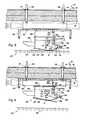
- the holder assembly 24 is in its uppermost position as shown in FIGURE 1 and wherein the press bar assembly 48 is in its up or home position.
- both the holder assembly 24 and the press bar assembly 48 move in unison to a pick-up position immediately adjacent the glass sheet G.
- the holder assembly 24 lifts the sheet of glass G while the press bar assembly 48 moves in unison with the holder assembly 24 as shown in FIGURE 4.
- the frame assembly 40 then moves downwardly relative to the holder assembly 24 to thereby allow each counterbalance 56 to rotate downwardly about the pivots 72 until the link assemblies 70 engage the stops 74, at which point the bending member 50 is located below the glass sheet G.
- a curved mold 76 is then moved under the holder 26 as shown in FIGURE 9 and the holder 26 is moved downwardly toward the mold 76 to decrease the distance between the lower surface 28 of the holder 26 and the mold 76. Thereafter, the partially bent sheet of glass G is dropped downwardly by termination of the vacuum drawn at the surface 28. Gravity then causes the sheet of glass to sag to the shape of the mold ring 76. The ends of the glass sheet G are thus effectively bent upwardly by the downward sagging of the central portion of the glass sheet G as shown in FIGURE 10.
- the bending member 50 facilitates deep bending of the glass sheets in that a higher bending force can be applied by the bending member 50 as the glass sheet is held by the holder 26 at its downwardly curved face thereof. Because a higher bending ,force can be used, the bending temperature may be reduced, thereby resulting in less distortion during the bending process.
- the bending member 50 may be aligned relative to the holder assembly 24 outside of the furnace environment for maintenance purposes without compromising the accuracy of their relative positions.
- the conveyor 20 or its rolls 22, need not be modified to accommodate the bending member 50.
Landscapes
- Chemical & Material Sciences (AREA)
- Engineering & Computer Science (AREA)
- Materials Engineering (AREA)
- Organic Chemistry (AREA)
- Re-Forming, After-Treatment, Cutting And Transporting Of Glass Products (AREA)
- Glass Compositions (AREA)
- Medicines Containing Material From Animals Or Micro-Organisms (AREA)
- Saccharide Compounds (AREA)
- Laminated Bodies (AREA)
- Wrapping Of Specific Fragile Articles (AREA)
Priority Applications (1)
| Application Number | Priority Date | Filing Date | Title |
|---|---|---|---|
| AT84307134T ATE41407T1 (de) | 1983-10-20 | 1984-10-17 | Vorrichtung zum biegen von glasscheiben. |
Applications Claiming Priority (2)
| Application Number | Priority Date | Filing Date | Title |
|---|---|---|---|
| US543916 | 1983-10-20 | ||
| US06/543,916 US4514208A (en) | 1983-10-20 | 1983-10-20 | Apparatus for bending glass sheets |
Publications (3)
| Publication Number | Publication Date |
|---|---|
| EP0139524A2 true EP0139524A2 (fr) | 1985-05-02 |
| EP0139524A3 EP0139524A3 (en) | 1986-03-19 |
| EP0139524B1 EP0139524B1 (fr) | 1989-03-15 |
Family
ID=24170045
Family Applications (1)
| Application Number | Title | Priority Date | Filing Date |
|---|---|---|---|
| EP84307134A Expired EP0139524B1 (fr) | 1983-10-20 | 1984-10-17 | Dispositif pour le bombage des feuilles de verre |
Country Status (14)
| Country | Link |
|---|---|
| US (1) | US4514208A (fr) |
| EP (1) | EP0139524B1 (fr) |
| JP (1) | JPS60108329A (fr) |
| KR (1) | KR910003090B1 (fr) |
| AT (1) | ATE41407T1 (fr) |
| AU (1) | AU567370B2 (fr) |
| BR (1) | BR8405196A (fr) |
| CA (1) | CA1207533A (fr) |
| DE (1) | DE3477186D1 (fr) |
| ES (1) | ES536897A0 (fr) |
| FI (1) | FI77009C (fr) |
| IE (1) | IE56187B1 (fr) |
| NZ (1) | NZ209607A (fr) |
| ZA (1) | ZA847383B (fr) |
Cited By (8)
| Publication number | Priority date | Publication date | Assignee | Title |
|---|---|---|---|---|
| DE3527558A1 (de) * | 1985-08-01 | 1987-02-05 | Ver Glaswerke Gmbh | Verfahren und vorrichtungen zum biegen einer glasscheibe |
| FR2599357A1 (fr) * | 1986-06-02 | 1987-12-04 | Saint Gobain Vitrage | Procede pour bomber des feuilles de verre avec un faible rayon de courbure |
| FR2601668A1 (fr) * | 1986-07-16 | 1988-01-22 | Saint Gobain Vitrage | Perfectionnement au bombage de plaques de verre |
| FR2601667A1 (fr) * | 1986-07-16 | 1988-01-22 | Saint Gobain Vitrage | Positionnement des plaques de verre en vue de leur bombage |
| EP0298426A2 (fr) * | 1987-07-07 | 1989-01-11 | Asahi Glass Company Ltd. | Appareil de bombage de feuilles en verre |
| EP0389323A1 (fr) * | 1989-03-22 | 1990-09-26 | Selas S.A. | Installation pour incurver et tremper une feuille de verre |
| EP0613864A1 (fr) * | 1993-03-03 | 1994-09-07 | Pilkington Glass Limited | Bombage de feuille de verre |
| EP3102546A4 (fr) * | 2014-02-06 | 2017-08-23 | Glasstech, Inc. | Formage de feuilles de verre en trois étapes avec courbure transversale |
Families Citing this family (7)
| Publication number | Priority date | Publication date | Assignee | Title |
|---|---|---|---|---|
| JPS6345138A (ja) * | 1986-08-08 | 1988-02-26 | Asahi Glass Co Ltd | ガラス板の曲げ加工方法 |
| FR2618138B1 (fr) * | 1987-07-15 | 1989-12-01 | Saint Gobain Vitrage | Bombage de plaques de verre |
| US4892574A (en) * | 1988-07-11 | 1990-01-09 | Vitro Flex, S.A. | Apparatus for the horizontal bending and tempering of glass sheets |
| JP3139788B2 (ja) * | 1991-09-04 | 2001-03-05 | 日本板硝子株式会社 | 板ガラスの曲げ成形装置及び曲げ成形方法 |
| US7216511B2 (en) * | 2002-11-12 | 2007-05-15 | Hhh Tempering Systems, Inc. | Furnace apparatus and method for tempering low emissivity glass |
| US9809485B2 (en) | 2015-11-02 | 2017-11-07 | Glasstech, Inc. | Lift device for a glass processing system |
| WO2018137931A1 (fr) | 2017-01-30 | 2018-08-02 | Saint-Gobain Glass France | Procédé pour cintrer une plaque de verre |
Citations (3)
| Publication number | Priority date | Publication date | Assignee | Title |
|---|---|---|---|---|
| US3116993A (en) * | 1959-02-04 | 1964-01-07 | Pittsburgh Plate Glass Co | Glass bending |
| US4229200A (en) * | 1979-06-01 | 1980-10-21 | Ppg Industries, Inc. | Drop forming glass sheets with auxiliary shaping means |
| US4305746A (en) * | 1980-05-01 | 1981-12-15 | Libbey-Owens-Ford Company | Method of and apparatus for bending glass sheets |
Family Cites Families (2)
| Publication number | Priority date | Publication date | Assignee | Title |
|---|---|---|---|---|
| US4277276A (en) * | 1980-03-17 | 1981-07-07 | Ppg Industries, Inc. | Method and apparatus for shaping glass sheets using deformable vacuum mold |
| US4501603A (en) * | 1983-03-30 | 1985-02-26 | Ppg Industries, Inc. | Method and apparatus for shaping glass sheets to complicated shapes |
-
1983
- 1983-10-20 US US06/543,916 patent/US4514208A/en not_active Expired - Lifetime
-
1984
- 1984-09-17 CA CA000463277A patent/CA1207533A/fr not_active Expired
- 1984-09-19 IE IE2384/84A patent/IE56187B1/xx unknown
- 1984-09-19 ZA ZA847383A patent/ZA847383B/xx unknown
- 1984-09-20 NZ NZ209607A patent/NZ209607A/en unknown
- 1984-09-26 AU AU33609/84A patent/AU567370B2/en not_active Ceased
- 1984-10-15 BR BR8405196A patent/BR8405196A/pt not_active IP Right Cessation
- 1984-10-16 JP JP59217205A patent/JPS60108329A/ja active Granted
- 1984-10-17 DE DE8484307134T patent/DE3477186D1/de not_active Expired
- 1984-10-17 EP EP84307134A patent/EP0139524B1/fr not_active Expired
- 1984-10-17 AT AT84307134T patent/ATE41407T1/de not_active IP Right Cessation
- 1984-10-18 KR KR1019840006493A patent/KR910003090B1/ko active IP Right Grant
- 1984-10-19 ES ES536897A patent/ES536897A0/es active Granted
- 1984-10-19 FI FI844134A patent/FI77009C/fi not_active IP Right Cessation
Patent Citations (3)
| Publication number | Priority date | Publication date | Assignee | Title |
|---|---|---|---|---|
| US3116993A (en) * | 1959-02-04 | 1964-01-07 | Pittsburgh Plate Glass Co | Glass bending |
| US4229200A (en) * | 1979-06-01 | 1980-10-21 | Ppg Industries, Inc. | Drop forming glass sheets with auxiliary shaping means |
| US4305746A (en) * | 1980-05-01 | 1981-12-15 | Libbey-Owens-Ford Company | Method of and apparatus for bending glass sheets |
Cited By (17)
| Publication number | Priority date | Publication date | Assignee | Title |
|---|---|---|---|---|
| EP0211755A1 (fr) * | 1985-08-01 | 1987-02-25 | Saint Gobain Vitrage International | Forme de bombage avec parties latérales roulant sur la feuille de verre |
| DE3527558A1 (de) * | 1985-08-01 | 1987-02-05 | Ver Glaswerke Gmbh | Verfahren und vorrichtungen zum biegen einer glasscheibe |
| FR2599357A1 (fr) * | 1986-06-02 | 1987-12-04 | Saint Gobain Vitrage | Procede pour bomber des feuilles de verre avec un faible rayon de courbure |
| FR2601668A1 (fr) * | 1986-07-16 | 1988-01-22 | Saint Gobain Vitrage | Perfectionnement au bombage de plaques de verre |
| FR2601667A1 (fr) * | 1986-07-16 | 1988-01-22 | Saint Gobain Vitrage | Positionnement des plaques de verre en vue de leur bombage |
| EP0255422A1 (fr) * | 1986-07-16 | 1988-02-03 | Saint-Gobain Vitrage International | Perfectionnement au bombage de plaques de verre |
| EP0256905A1 (fr) * | 1986-07-16 | 1988-02-24 | Saint-Gobain Vitrage International | Positionnement des plaques de verre en vue de leur bombage |
| EP0298426A3 (en) * | 1987-07-07 | 1990-09-26 | Asahi Glass Company Ltd. | Glass sheet bending apparatus |
| EP0298426A2 (fr) * | 1987-07-07 | 1989-01-11 | Asahi Glass Company Ltd. | Appareil de bombage de feuilles en verre |
| EP0389323A1 (fr) * | 1989-03-22 | 1990-09-26 | Selas S.A. | Installation pour incurver et tremper une feuille de verre |
| FR2644775A1 (fr) * | 1989-03-22 | 1990-09-28 | Selas Sa | Installation pour incurver et tremper une feuille de verre |
| US4976763A (en) * | 1989-03-22 | 1990-12-11 | Selas S.A. | Installation for curving and tempering a sheet of glass |
| EP0613864A1 (fr) * | 1993-03-03 | 1994-09-07 | Pilkington Glass Limited | Bombage de feuille de verre |
| US5437703A (en) * | 1993-03-03 | 1995-08-01 | Pilkington Glass Limited | Bending glass sheets |
| TR28100A (tr) * | 1993-03-03 | 1996-01-02 | Pilkington Glass Ltd | Cam tabakalarin bükülmesi. |
| EP3102546A4 (fr) * | 2014-02-06 | 2017-08-23 | Glasstech, Inc. | Formage de feuilles de verre en trois étapes avec courbure transversale |
| US10246364B2 (en) | 2014-02-06 | 2019-04-02 | Glasstech, Inc. | Method for three stage forming a hot glass sheet with transverse curvature |
Also Published As
| Publication number | Publication date |
|---|---|
| NZ209607A (en) | 1986-06-11 |
| AU567370B2 (en) | 1987-11-19 |
| ES8600173A1 (es) | 1985-09-16 |
| KR910003090B1 (ko) | 1991-05-18 |
| FI844134L (fi) | 1985-04-21 |
| IE56187B1 (en) | 1991-05-08 |
| CA1207533A (fr) | 1986-07-15 |
| US4514208A (en) | 1985-04-30 |
| AU3360984A (en) | 1985-04-26 |
| EP0139524B1 (fr) | 1989-03-15 |
| KR850003361A (ko) | 1985-06-17 |
| FI844134A0 (fi) | 1984-10-19 |
| DE3477186D1 (en) | 1989-04-20 |
| BR8405196A (pt) | 1985-08-27 |
| EP0139524A3 (en) | 1986-03-19 |
| FI77009C (fi) | 1989-01-10 |
| IE842384L (en) | 1985-04-20 |
| FI77009B (fi) | 1988-09-30 |
| ATE41407T1 (de) | 1989-04-15 |
| JPS60108329A (ja) | 1985-06-13 |
| ES536897A0 (es) | 1985-09-16 |
| ZA847383B (en) | 1985-04-24 |
| JPS6319449B2 (fr) | 1988-04-22 |
Similar Documents
| Publication | Publication Date | Title |
|---|---|---|
| US4282026A (en) | Apparatus for bending and tempering glass | |
| US4437871A (en) | Apparatus and method for bending glass sheets | |
| US4514208A (en) | Apparatus for bending glass sheets | |
| EP0005306B1 (fr) | Appareil et procédé pour cintrer du verre | |
| EP0003391B1 (fr) | Appareil pour le cintrage et la trempe du verre | |
| EP0183418B1 (fr) | Procédé et appareil de formage de feuilles de verre | |
| US4265650A (en) | Method of bending glass sheets in unison to complicated shapes | |
| EP0885851B1 (fr) | Procédé et appareil de bombage de feuilles de verre | |
| US4979977A (en) | Bending iron having member to effect reverse bend and method of using same | |
| US4297118A (en) | Controlling overheating of vacuum mold used to shape glass sheets | |
| US4361432A (en) | Apparatus and method for removing a glass sheet from a carrier | |
| US4285715A (en) | Cycle of mold movement while press bending glass sheets | |
| CA1152327A (fr) | Appareil pour le formage des feuilles de verre au moyen d'un moule diformable, a depression, et methode connexe | |
| JPH0834629A (ja) | ガラス板の曲げ焼もどし方法及び装置 | |
| US4437872A (en) | Apparatus for bending and tempering glass sheets | |
| US4252552A (en) | Shaping glass sheets using molds of different shapes | |
| US4221580A (en) | Glass sheet vacuum molding apparatus with uniform release means | |
| JPS6141854B2 (fr) | ||
| US4670036A (en) | Conveying, supporting and shaping glass sheets | |
| CA1283294C (fr) | Moule-presse a surface developpee | |
| US4368065A (en) | Method and apparatus to remove bent, tempered glass sheets from a cooling station | |
| US4364765A (en) | Apparatus and method for handling heated glass sheets | |
| US4430111A (en) | Method and apparatus to remove sharply bent, tempered glass sheets from a cooling station | |
| EP0003392B1 (fr) | Système de fixation par le vide et méthode d'application pour le cintrage de verre | |
| US4199341A (en) | Glass lift mechanism for and method of press bending glass sheets |
Legal Events
| Date | Code | Title | Description |
|---|---|---|---|
| PUAI | Public reference made under article 153(3) epc to a published international application that has entered the european phase |
Free format text: ORIGINAL CODE: 0009012 |
|
| AK | Designated contracting states |
Designated state(s): AT BE CH DE FR GB IT LI LU NL SE |
|
| PUAL | Search report despatched |
Free format text: ORIGINAL CODE: 0009013 |
|
| AK | Designated contracting states |
Kind code of ref document: A3 Designated state(s): AT BE CH DE FR GB IT LI LU NL SE |
|
| 17P | Request for examination filed |
Effective date: 19860819 |
|
| 17Q | First examination report despatched |
Effective date: 19870327 |
|
| GRAA | (expected) grant |
Free format text: ORIGINAL CODE: 0009210 |
|
| AK | Designated contracting states |
Kind code of ref document: B1 Designated state(s): AT BE CH DE FR GB IT LI LU NL SE |
|
| PG25 | Lapsed in a contracting state [announced via postgrant information from national office to epo] |
Ref country code: NL Effective date: 19890315 Ref country code: AT Effective date: 19890315 |
|
| REF | Corresponds to: |
Ref document number: 41407 Country of ref document: AT Date of ref document: 19890415 Kind code of ref document: T |
|
| REF | Corresponds to: |
Ref document number: 3477186 Country of ref document: DE Date of ref document: 19890420 |
|
| ET | Fr: translation filed | ||
| ITF | It: translation for a ep patent filed |
Owner name: STUDIO TORTA SOCIETA' SEMPLICE |
|
| NLV1 | Nl: lapsed or annulled due to failure to fulfill the requirements of art. 29p and 29m of the patents act | ||
| PG25 | Lapsed in a contracting state [announced via postgrant information from national office to epo] |
Ref country code: LU Free format text: LAPSE BECAUSE OF NON-PAYMENT OF DUE FEES Effective date: 19891031 |
|
| PLBE | No opposition filed within time limit |
Free format text: ORIGINAL CODE: 0009261 |
|
| STAA | Information on the status of an ep patent application or granted ep patent |
Free format text: STATUS: NO OPPOSITION FILED WITHIN TIME LIMIT |
|
| 26N | No opposition filed | ||
| PGFP | Annual fee paid to national office [announced via postgrant information from national office to epo] |
Ref country code: GB Payment date: 19901008 Year of fee payment: 7 |
|
| PGFP | Annual fee paid to national office [announced via postgrant information from national office to epo] |
Ref country code: SE Payment date: 19901012 Year of fee payment: 7 Ref country code: FR Payment date: 19901012 Year of fee payment: 7 |
|
| ITTA | It: last paid annual fee | ||
| PGFP | Annual fee paid to national office [announced via postgrant information from national office to epo] |
Ref country code: CH Payment date: 19901102 Year of fee payment: 7 |
|
| PGFP | Annual fee paid to national office [announced via postgrant information from national office to epo] |
Ref country code: LU Payment date: 19901106 Year of fee payment: 7 |
|
| PGFP | Annual fee paid to national office [announced via postgrant information from national office to epo] |
Ref country code: BE Payment date: 19901129 Year of fee payment: 7 |
|
| PGFP | Annual fee paid to national office [announced via postgrant information from national office to epo] |
Ref country code: DE Payment date: 19901130 Year of fee payment: 7 |
|
| EPTA | Lu: last paid annual fee | ||
| PG25 | Lapsed in a contracting state [announced via postgrant information from national office to epo] |
Ref country code: GB Effective date: 19911017 |
|
| PG25 | Lapsed in a contracting state [announced via postgrant information from national office to epo] |
Ref country code: SE Effective date: 19911018 |
|
| PG25 | Lapsed in a contracting state [announced via postgrant information from national office to epo] |
Ref country code: LI Effective date: 19911031 Ref country code: CH Effective date: 19911031 Ref country code: BE Effective date: 19911031 |
|
| BERE | Be: lapsed |
Owner name: GLASSTECH INC. Effective date: 19911031 |
|
| GBPC | Gb: european patent ceased through non-payment of renewal fee | ||
| PG25 | Lapsed in a contracting state [announced via postgrant information from national office to epo] |
Ref country code: FR Effective date: 19920630 |
|
| REG | Reference to a national code |
Ref country code: CH Ref legal event code: PL |
|
| PG25 | Lapsed in a contracting state [announced via postgrant information from national office to epo] |
Ref country code: DE Effective date: 19920701 |
|
| REG | Reference to a national code |
Ref country code: FR Ref legal event code: ST |
|
| EUG | Se: european patent has lapsed |
Ref document number: 84307134.1 Effective date: 19920510 |