EP0138489B1 - Apparat und Verfahren zur Behandlung von Zellen mit Strahlen - Google Patents
Apparat und Verfahren zur Behandlung von Zellen mit Strahlen Download PDFInfo
- Publication number
- EP0138489B1 EP0138489B1 EP84306667A EP84306667A EP0138489B1 EP 0138489 B1 EP0138489 B1 EP 0138489B1 EP 84306667 A EP84306667 A EP 84306667A EP 84306667 A EP84306667 A EP 84306667A EP 0138489 B1 EP0138489 B1 EP 0138489B1
- Authority
- EP
- European Patent Office
- Prior art keywords
- tube
- radiation source
- cells
- chamber
- cassette
- Prior art date
- Legal status (The legal status is an assumption and is not a legal conclusion. Google has not performed a legal analysis and makes no representation as to the accuracy of the status listed.)
- Expired
Links
- 230000005855 radiation Effects 0.000 title claims description 34
- 238000000034 method Methods 0.000 title claims description 12
- 210000004027 cell Anatomy 0.000 claims description 40
- 239000012530 fluid Substances 0.000 claims description 13
- 150000001875 compounds Chemical class 0.000 claims description 8
- 230000001678 irradiating effect Effects 0.000 claims description 7
- 238000007789 sealing Methods 0.000 claims description 7
- 210000000265 leukocyte Anatomy 0.000 claims description 5
- BUNGCZLFHHXKBX-UHFFFAOYSA-N 8-methoxypsoralen Natural products C1=CC(=O)OC2=C1C=C1CCOC1=C2OC BUNGCZLFHHXKBX-UHFFFAOYSA-N 0.000 claims description 4
- QXKHYNVANLEOEG-UHFFFAOYSA-N Methoxsalen Chemical compound C1=CC(=O)OC2=C1C=C1C=COC1=C2OC QXKHYNVANLEOEG-UHFFFAOYSA-N 0.000 claims description 4
- 229960004469 methoxsalen Drugs 0.000 claims description 4
- SQBBOVROCFXYBN-UHFFFAOYSA-N methoxypsoralen Natural products C1=C2OC(=O)C(OC)=CC2=CC2=C1OC=C2 SQBBOVROCFXYBN-UHFFFAOYSA-N 0.000 claims description 4
- 238000001228 spectrum Methods 0.000 claims description 3
- 238000002211 ultraviolet spectrum Methods 0.000 claims description 2
- 210000004369 blood Anatomy 0.000 description 24
- 239000008280 blood Substances 0.000 description 24
- 239000000463 material Substances 0.000 description 6
- ZCCUUQDIBDJBTK-UHFFFAOYSA-N psoralen Chemical compound C1=C2OC(=O)C=CC2=CC2=C1OC=C2 ZCCUUQDIBDJBTK-UHFFFAOYSA-N 0.000 description 6
- 230000000694 effects Effects 0.000 description 5
- 125000006850 spacer group Chemical group 0.000 description 5
- 238000001816 cooling Methods 0.000 description 4
- 230000008878 coupling Effects 0.000 description 4
- 238000010168 coupling process Methods 0.000 description 4
- 238000005859 coupling reaction Methods 0.000 description 4
- 238000007599 discharging Methods 0.000 description 4
- 210000004698 lymphocyte Anatomy 0.000 description 4
- 230000035899 viability Effects 0.000 description 4
- YMWUJEATGCHHMB-UHFFFAOYSA-N Dichloromethane Chemical compound ClCCl YMWUJEATGCHHMB-UHFFFAOYSA-N 0.000 description 3
- 239000000835 fiber Substances 0.000 description 3
- 239000001963 growth medium Substances 0.000 description 3
- 239000000243 solution Substances 0.000 description 3
- 239000002904 solvent Substances 0.000 description 3
- 238000003466 welding Methods 0.000 description 3
- VXGRJERITKFWPL-UHFFFAOYSA-N 4',5'-Dihydropsoralen Natural products C1=C2OC(=O)C=CC2=CC2=C1OCC2 VXGRJERITKFWPL-UHFFFAOYSA-N 0.000 description 2
- 239000004593 Epoxy Substances 0.000 description 2
- NIXOWILDQLNWCW-UHFFFAOYSA-N acrylic acid group Chemical group C(C=C)(=O)O NIXOWILDQLNWCW-UHFFFAOYSA-N 0.000 description 2
- 230000002411 adverse Effects 0.000 description 2
- 230000017531 blood circulation Effects 0.000 description 2
- 230000001413 cellular effect Effects 0.000 description 2
- LOKCTEFSRHRXRJ-UHFFFAOYSA-I dipotassium trisodium dihydrogen phosphate hydrogen phosphate dichloride Chemical compound P(=O)(O)(O)[O-].[K+].P(=O)(O)([O-])[O-].[Na+].[Na+].[Cl-].[K+].[Cl-].[Na+] LOKCTEFSRHRXRJ-UHFFFAOYSA-I 0.000 description 2
- 210000003743 erythrocyte Anatomy 0.000 description 2
- 239000002953 phosphate buffered saline Substances 0.000 description 2
- 230000037452 priming Effects 0.000 description 2
- 230000008569 process Effects 0.000 description 2
- 238000012546 transfer Methods 0.000 description 2
- 108091003079 Bovine Serum Albumin Proteins 0.000 description 1
- 229920002284 Cellulose triacetate Polymers 0.000 description 1
- HTTJABKRGRZYRN-UHFFFAOYSA-N Heparin Chemical compound OC1C(NC(=O)C)C(O)OC(COS(O)(=O)=O)C1OC1C(OS(O)(=O)=O)C(O)C(OC2C(C(OS(O)(=O)=O)C(OC3C(C(O)C(O)C(O3)C(O)=O)OS(O)(=O)=O)C(CO)O2)NS(O)(=O)=O)C(C(O)=O)O1 HTTJABKRGRZYRN-UHFFFAOYSA-N 0.000 description 1
- 239000006146 Roswell Park Memorial Institute medium Substances 0.000 description 1
- 241001342522 Vampyrum spectrum Species 0.000 description 1
- NNLVGZFZQQXQNW-ADJNRHBOSA-N [(2r,3r,4s,5r,6s)-4,5-diacetyloxy-3-[(2s,3r,4s,5r,6r)-3,4,5-triacetyloxy-6-(acetyloxymethyl)oxan-2-yl]oxy-6-[(2r,3r,4s,5r,6s)-4,5,6-triacetyloxy-2-(acetyloxymethyl)oxan-3-yl]oxyoxan-2-yl]methyl acetate Chemical compound O([C@@H]1O[C@@H]([C@H]([C@H](OC(C)=O)[C@H]1OC(C)=O)O[C@H]1[C@@H]([C@@H](OC(C)=O)[C@H](OC(C)=O)[C@@H](COC(C)=O)O1)OC(C)=O)COC(=O)C)[C@@H]1[C@@H](COC(C)=O)O[C@@H](OC(C)=O)[C@H](OC(C)=O)[C@H]1OC(C)=O NNLVGZFZQQXQNW-ADJNRHBOSA-N 0.000 description 1
- 238000010521 absorption reaction Methods 0.000 description 1
- WYTGDNHDOZPMIW-RCBQFDQVSA-N alstonine Natural products C1=CC2=C3C=CC=CC3=NC2=C2N1C[C@H]1[C@H](C)OC=C(C(=O)OC)[C@H]1C2 WYTGDNHDOZPMIW-RCBQFDQVSA-N 0.000 description 1
- 230000004075 alteration Effects 0.000 description 1
- 230000015572 biosynthetic process Effects 0.000 description 1
- 210000000601 blood cell Anatomy 0.000 description 1
- 239000001045 blue dye Substances 0.000 description 1
- HGAZMNJKRQFZKS-UHFFFAOYSA-N chloroethene;ethenyl acetate Chemical compound ClC=C.CC(=O)OC=C HGAZMNJKRQFZKS-UHFFFAOYSA-N 0.000 description 1
- 230000004087 circulation Effects 0.000 description 1
- 238000004891 communication Methods 0.000 description 1
- 238000010276 construction Methods 0.000 description 1
- 238000007796 conventional method Methods 0.000 description 1
- 230000003247 decreasing effect Effects 0.000 description 1
- 201000010099 disease Diseases 0.000 description 1
- 208000037265 diseases, disorders, signs and symptoms Diseases 0.000 description 1
- 229920006332 epoxy adhesive Polymers 0.000 description 1
- 239000012894 fetal calf serum Substances 0.000 description 1
- 230000009760 functional impairment Effects 0.000 description 1
- 239000011521 glass Substances 0.000 description 1
- 238000010438 heat treatment Methods 0.000 description 1
- 229960002897 heparin Drugs 0.000 description 1
- 229920000669 heparin Polymers 0.000 description 1
- 238000005286 illumination Methods 0.000 description 1
- 238000000338 in vitro Methods 0.000 description 1
- 230000005764 inhibitory process Effects 0.000 description 1
- 230000003993 interaction Effects 0.000 description 1
- 239000012528 membrane Substances 0.000 description 1
- 230000002503 metabolic effect Effects 0.000 description 1
- 238000000465 moulding Methods 0.000 description 1
- 150000007523 nucleic acids Chemical class 0.000 description 1
- 102000039446 nucleic acids Human genes 0.000 description 1
- 108020004707 nucleic acids Proteins 0.000 description 1
- 210000000056 organ Anatomy 0.000 description 1
- 238000012261 overproduction Methods 0.000 description 1
- 239000004033 plastic Substances 0.000 description 1
- 229920003023 plastic Polymers 0.000 description 1
- 239000004417 polycarbonate Substances 0.000 description 1
- 229920000515 polycarbonate Polymers 0.000 description 1
- 230000003134 recirculating effect Effects 0.000 description 1
- 238000012360 testing method Methods 0.000 description 1
- 239000003104 tissue culture media Substances 0.000 description 1
- 238000012549 training Methods 0.000 description 1
- 239000012780 transparent material Substances 0.000 description 1
Images


Classifications
-
- A—HUMAN NECESSITIES
- A61—MEDICAL OR VETERINARY SCIENCE; HYGIENE
- A61M—DEVICES FOR INTRODUCING MEDIA INTO, OR ONTO, THE BODY; DEVICES FOR TRANSDUCING BODY MEDIA OR FOR TAKING MEDIA FROM THE BODY; DEVICES FOR PRODUCING OR ENDING SLEEP OR STUPOR
- A61M1/00—Suction or pumping devices for medical purposes; Devices for carrying-off, for treatment of, or for carrying-over, body-liquids; Drainage systems
- A61M1/36—Other treatment of blood in a by-pass of the natural circulatory system, e.g. temperature adaptation, irradiation ; Extra-corporeal blood circuits
- A61M1/3681—Other treatment of blood in a by-pass of the natural circulatory system, e.g. temperature adaptation, irradiation ; Extra-corporeal blood circuits by irradiation
-
- A—HUMAN NECESSITIES
- A61—MEDICAL OR VETERINARY SCIENCE; HYGIENE
- A61M—DEVICES FOR INTRODUCING MEDIA INTO, OR ONTO, THE BODY; DEVICES FOR TRANSDUCING BODY MEDIA OR FOR TAKING MEDIA FROM THE BODY; DEVICES FOR PRODUCING OR ENDING SLEEP OR STUPOR
- A61M1/00—Suction or pumping devices for medical purposes; Devices for carrying-off, for treatment of, or for carrying-over, body-liquids; Drainage systems
- A61M1/36—Other treatment of blood in a by-pass of the natural circulatory system, e.g. temperature adaptation, irradiation ; Extra-corporeal blood circuits
- A61M1/3621—Extra-corporeal blood circuits
- A61M1/3622—Extra-corporeal blood circuits with a cassette forming partially or totally the blood circuit
- A61M1/36226—Constructional details of cassettes, e.g. specific details on material or shape
- A61M1/362262—Details of incorporated reservoirs
-
- A—HUMAN NECESSITIES
- A61—MEDICAL OR VETERINARY SCIENCE; HYGIENE
- A61M—DEVICES FOR INTRODUCING MEDIA INTO, OR ONTO, THE BODY; DEVICES FOR TRANSDUCING BODY MEDIA OR FOR TAKING MEDIA FROM THE BODY; DEVICES FOR PRODUCING OR ENDING SLEEP OR STUPOR
- A61M1/00—Suction or pumping devices for medical purposes; Devices for carrying-off, for treatment of, or for carrying-over, body-liquids; Drainage systems
- A61M1/36—Other treatment of blood in a by-pass of the natural circulatory system, e.g. temperature adaptation, irradiation ; Extra-corporeal blood circuits
- A61M1/3681—Other treatment of blood in a by-pass of the natural circulatory system, e.g. temperature adaptation, irradiation ; Extra-corporeal blood circuits by irradiation
- A61M1/3683—Other treatment of blood in a by-pass of the natural circulatory system, e.g. temperature adaptation, irradiation ; Extra-corporeal blood circuits by irradiation using photoactive agents
Definitions
- This invention relates to the field of treating cells with radiation and specifically relates to the extracorporeal treatment of blood cells with U.V. radiation.
- lymphocytes a number of human disease states may be characterized by the overproduction of certain types of leukocytes, including lymphocytes, in comparison to other populations of cells which normally comprise whole blood. Excessive lymphocyte populations result in numerous adverse effects to the patients including the functional impairment of bodily organs eventually resulting in fatality.
- US-A-4,321,919 to Edelson describes a method for treating whole blood whereby such populations may be decreased.
- the method comprises treating the whole blood with dissolved psoralen of a type capable of forming photoadducts with DNA in the presence of U.V.A. radiation in the range of about 320 to 400 nanometers.
- the covalent bonding that results between the psoralen and the lymphocyte nucleic acid results in lymphocyte metabolic inhibition of the thusly treated cells. These cells are then returned to the patient.
- the present invention be simple to produce, and be capable of use by persons having a minimal level of training.
- the sample is passed around a plurality of fibers which optically relay the radiation from the radiation source.
- these devices require that the fiber optics function very poorly so that the radiation is "lost" through the walls of the fibers, thereby irradiating the cells.
- such systems are characterized by inefficient energy coupling thereby requiring very large and expensive radiation sources.
- the fluorescent black light source typically of tubular shape, is coaxially mounted in a tube of larger diameter, the ends of said outer tube being sealed with the radiation source.
- the outer tube is also provided with an inlet for receiving the cells to be irradiated and an outlet for discharging irradiated cells.
- a second outer tube of even larger diameter is coaxially mounted on the previously described device, its ends also in sealing communication with the first outer tube.
- the second tube further comprises inlet and outlet means for receiving and discharging respectively cells to be irradiated.
- the chamber formed by the inner tube in sealing arrangement with the radiation source serves as a cooling chamber for reducing the heating effects of the bulb.
- a plurality of the previously described tubes are arranged to form a cassette which is preferably disposable.
- Flow takes place serially through each of the described tubular arrangements, preferably in a serpentine manner, whereby each tubular apparatus is preferably held vertically and the predominant blood flow therethrough is in a vertical fashion whereby air bubbles and the like are efficaciously flushed out.
- the embodiment further provides for an inlet and outlet of blood at one end of the cassette and specifically, provides for the blood inlet to be ideally positioned at the bottom most portion of the first tubular apparatus.
- the blood outlet advantageously communicates with the top of the last most cylindrical irradiating apparatus.
- body cells to be treated by irradiation with the aforedescribed device are removed from the body and passed through the chamber surrounding the radiation source.
- the cells may then be returned to the body.
- the present invention comprises a method for irradiating biological cells without reintroducing the cells into the same body from which they have been removed, as defined in Claim 5.
- Such treatment may also involve contacting the cells to be irradiated with a compound, such as those available in the psoralen class, which is activated by radiation from the light source.
- Activated as used herein means that the compound has substantially no effect prior to irradiation, and following irradiation affects the treated cells in a distinguishable and detectable manner.
- a distinguishable and detectable manner may include, for instance, the disruption of membrane integrity and the alteration of DNA within the cell, resulting in the substantial loss of effectiveness or viability of the thusly treated cell.
- U.V. activated compounds in the psoralen class are known, 8-methoxy psoralen is the compound of choice.
- An effective radiation for this compound, and many psoralens in general, is the ultraviolet spectrum in the range of approximately 320 to 400 nanometers.
- a light source which provides such a spectrum is the Sylvania F8TS/BLB 8W Black Light T5 Blue Bulb.
- Substantial equivalents are also available from other manufacturers such as General Electric. These bulbs traditionally come in the small "fluorescent" type tube arrangement for which suitable electrical sockets and power supplies are readily available.
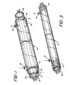
- a light source 10 is shown with tubes 11 and 13 coaxially mounted thereon.
- the inner tube 11 is preferably provided with spacer rings 16 mounted on the end thereof in order to maintain coaxial alignment with tube 10.
- Permanent sealing connection may be made by application of a suitable sealing or cementing material such as the class of epoxy adhesives or solvents such as methylene chloride, particularly useful for "welding" various classes of plastics together.
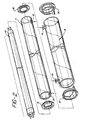
- the inner tube is provided with orifices 12 permitting the free flow of convection currents through the chamber thereby cooling the light source 10.
- any suitable means such as forced air and the like.
- inner tube 11 is made from a substantially U.V. transparent material such as acrylic, cellulose triacetate or a suitable rigid PVC. Based on cost and availability, as well as U.V. transparency, acrylic tends to be the most preferred material and accordingly, is ideally employed in the best embodiment.
- a substantially U.V. transparent material such as acrylic, cellulose triacetate or a suitable rigid PVC. Based on cost and availability, as well as U.V. transparency, acrylic tends to be the most preferred material and accordingly, is ideally employed in the best embodiment.
- an outer tube 13 is coaxially mounted onto the inner tube 11 advantageously by means of spacers 15.
- the mounting with the spacers 15 is accomplished in a sealing fashion typically by the application of a suitable solvent for chemically "welding" the outer tube 13, the spacer 15, and the inner tube 11 together.
- Outer tube 13 has further mounted thereon inlet and outlet 14 for receiving and discharging respectively the fluid sample to be irradiated.
- these inlets 14 are Luer type connectors.
- spacers 15 have a protruding "finger” type projection which is preferably disposed on the opposite wall from the inlet 14 and outlet 14. Such a projection advantageously reduces stagnant fluid volumes which would otherwise accumulate in that location.
- a projection may take the form of virtually any shape and, if desired, may be eliminated all together.
- Fig. 3 depicts another embodiment of the instant invention wherein a single chamber, formed by the tube 11 in coaxial orientation with bulb 10 with the ends thereof sealed with a suitable material such as epoxy 17, is used.
- a suitable material such as epoxy 17, is used.
- Tube 11 is outfitted with inlet and outlets 14 for receiving and discharging the fluid sample.
- Orientation of flow within the chamber is not important and may be in either direction, however, if a plurality of devices of either the type shown in Fig. 1 or Fig. 3 are employed such as shown in Fig. 4, they are preferably aligned in a vertical fashion and flow is arranged to proceed from bottom to top. Even if a single device is employed, this is the preferred flow arrangement for eliminating air bubbles which might otherwise become trapped in an alternative arrangement.
- Fig. 4 shows the most preferred embodiment referred to herein as a cassette.
- the cassette employs a plurality of irradiating chambers 20 each of which is substantially similar in structure to the embodiment shown in Fig. 1.
- the ideal arrangement has six such irradiating chambers 20, however, more or less such chambers may be employed, subject only to the constraints of practical construction and ease of handling. It will be readily understood, of course, that increasing the number of irradiation tubes and forcing the blood to flow through each of them, accordingly increases the amount of irradiation to the fluid flowing therethrough.
- blood is communicated to the irradiating chamber 20 through inlet 21 which may be either a Luer lock or simply an inlet pipe to which a tubing set may be attached by any suitable means such as solvent welding and the like.
- the fluid to be irradiated then flows in a generally upward direction and then downwardly through cross connecting means 22 which may comprise a flexible or inflexible tubing connecting chamber outlet 23 to chamber inlet 24 of the next irradiation chamber.
- cross connecting means 22 may comprise a flexible or inflexible tubing connecting chamber outlet 23 to chamber inlet 24 of the next irradiation chamber.
- the reverse directions may be also employed, as the flow of the fluid through the irradiation chamber 20 is equally effected by the illumination from lamps 25 irregardless of flow.
- the fluid reaches outlet 23 of the last irradiation chamber 20 and is emitted from the cassette through the cassette outlet 27.
- this outlet is shown to be at the same side as the cassette inlet 21 via outlet connecting tubing 28.
- the cassette outlet 27 may be in a form similar to cassette inlet 21 directly at the last chamber outlet 23.
- Each irradiation chamber 20 has tabs 29 holding the irradiation lamp 25 in place within the irradiation chamber. The openings between tabs in combination with inner wall 26 allow the formation of an air space surrounding the lamp 25 which freely communicates with the atmosphere thereby providing cooling in much the same manner as obtained from the interior cooling chamber formed by tube 11 in Fig. 2.
- Figure 5 depicts the preferred embodiment of the blood treatment center 30 which employs the cassette of Figure 4 in sliding drawer 37.
- the flow of heparin or other clot preventing solution through pump 31 via a tubing set (not shown) and the flow of blood through pump 32 from centifuge 33 is controlled by clamps 36A, B and C in turn controlled by control panel 39.
- the centrifuge 33 is a continuous flow type whereby the operator, by viewing through port 34, determines when a leukocyte rich portion of whole blood is obtained. All solutions are collected in bags (not shown) which hang beside internal access panels 38. After treatment, treated and nontreated blood portions are hung on drip stand 35 and reinfused into the patient.
- a device as that depicted in Fig. 3, having ends sealed with a combination O ring and epoxy material was employed with a Sylvania F8T5/BLB Lamp.
- a simple recirculating system was constructed comprising a flexible bag for holding the blood and communicating with inlet located at the bottom of the vertically arranged device. The blood was permitted to flow around the lamp, up through the chamber out the exit orifice whereupon it was returned to the bag. Connections were by means of a flexible tube (Tygon tubing) which was run through a roller bearing type pump. Circuit volume was 150 ml of diluted fresh human blood containing 62 ng/ml of 8-methoxy psoralen.
- the erythrocyte concentration was 6.7x10 8 per ml and the leukocyte concentration was 1.4x10 6 per mi.
- the priming volume of the device was 25 ml with a blood film thickness of 1.8 mm (0.070 inches) i.e. the distance between the bulb and the inner surface of the surrounding jacket or tube was 1.8 mm (0.07 inches). Blood flow rate was maintained at 50 ml per minute.
- a pretreatment sample was taken prior to any U.V. exposure and then one sample was run through a circuit such as that described having one device therein and the sample irradiated with 63 joules per ml.
- Fig. 1 Three devices similar to that shown in Fig. 1 were arranged vertically and connected in serial fashion. Connections were made from the output to a Fenwall 350 cc transfer pack with the inlet thereof running through a blood pump and into the first device's inlet. The blood pump maintained flow at 50 ml per minute.
- the radiation source was a Sylvania F8T5/BLB lamp. Surrounding the lamp was an inner, U.V. transparent tube having a 2.2 cm (7/8") outer diameter. The outer polycarbonate tubing had a 2.54 cm (1") outer diameter.
- the test circuit was primed for 20 minutes with phosphate buffered saline (PBS) and then drained.
- PBS phosphate buffered saline
- the blood was permitted to circulate through the system for 20 minutes at 50 ml per minute without the lamps being turned on.
- a pretreatment sample (To) was taken.
- the lamps were turned on and the blood circulated for 1 hour and 25 minutes at which time sample T i was taken. Thereafter, the transfer pack was removed from the circuit the venous and arterial lines were connected together and the blood solution allowed to circulate for another 1 hour 20 minutes at which time sample T 2 was obtained.
- the effective surface area per cell was calculated to be 163 cm 2 , the effective length 23.5 cm, the priming volume per cell 28 ml, the blood film thickness approximately 1.6 millimeters and the average power per cell 5.5 milliwatts per cm 2.
- Sample T 1 represented cells irradiated with 94 joules per ml and T 2 represented cells irradiated with 190 joules per ml.
- the cells were maintained in vitro by addition of growth medium at a 1:1 proportion of cells to growth medium.
- Growth medium contained fetal calf serum 30% and 70% RPMI, a well-known tissue culture media.
- the thickness of the chamber containing the fluid sample, the flow rate of the sample therethrough, lamp power output and cellular concentrations will be advantageously designed in order to afford the desired application of energy to the fluid sample in order to obtain the effects required. Accordingly, the present invention also contemplates the use of any type of radiation source and is not to be limited to the broad band U.V. spectrum employed in the examples.
Landscapes
- Health & Medical Sciences (AREA)
- Heart & Thoracic Surgery (AREA)
- Vascular Medicine (AREA)
- Life Sciences & Earth Sciences (AREA)
- Engineering & Computer Science (AREA)
- Anesthesiology (AREA)
- Biomedical Technology (AREA)
- Hematology (AREA)
- Cardiology (AREA)
- Animal Behavior & Ethology (AREA)
- General Health & Medical Sciences (AREA)
- Public Health (AREA)
- Veterinary Medicine (AREA)
- External Artificial Organs (AREA)
- Radiation-Therapy Devices (AREA)
- Apparatus Associated With Microorganisms And Enzymes (AREA)
Claims (12)
Applications Claiming Priority (4)
| Application Number | Priority Date | Filing Date | Title |
|---|---|---|---|
| US53723183A | 1983-09-29 | 1983-09-29 | |
| US537231 | 1983-09-29 | ||
| US65060284A | 1984-09-17 | 1984-09-17 | |
| US650602 | 1984-09-17 |
Publications (2)
| Publication Number | Publication Date |
|---|---|
| EP0138489A1 EP0138489A1 (de) | 1985-04-24 |
| EP0138489B1 true EP0138489B1 (de) | 1987-12-23 |
Family
ID=27065421
Family Applications (1)
| Application Number | Title | Priority Date | Filing Date |
|---|---|---|---|
| EP84306667A Expired EP0138489B1 (de) | 1983-09-29 | 1984-09-28 | Apparat und Verfahren zur Behandlung von Zellen mit Strahlen |
Country Status (5)
| Country | Link |
|---|---|
| EP (1) | EP0138489B1 (de) |
| JP (1) | JPS60142862A (de) |
| AU (1) | AU566710B2 (de) |
| CA (1) | CA1253115A (de) |
| DE (1) | DE3468172D1 (de) |
Cited By (1)
| Publication number | Priority date | Publication date | Assignee | Title |
|---|---|---|---|---|
| RU2144385C1 (ru) * | 1997-05-13 | 2000-01-20 | Островский Владислав Казимирович | Способ повышения иммунных свойств переливаемой аутокрови |
Families Citing this family (19)
| Publication number | Priority date | Publication date | Assignee | Title |
|---|---|---|---|---|
| US4708715A (en) * | 1984-10-29 | 1987-11-24 | Mcneilab, Inc. | Light array assembly for photoactivation patient treatment system |
| US4681568A (en) | 1984-10-29 | 1987-07-21 | Mcneilab, Inc. | Valve apparatus for photoactivation patient treatment system |
| DE3650139T2 (de) * | 1985-07-05 | 1995-03-09 | Hutchinson Fred Cancer Res | Verfahren zum reduzieren der immunogenizität und zum induzieren immunologischer toleranz. |
| JPS62284656A (ja) * | 1986-06-03 | 1987-12-10 | 株式会社イーゼル | 血液の殺菌方法 |
| GB8630102D0 (en) * | 1986-12-17 | 1987-01-28 | Gunn A | Blood processing device |
| AU2616788A (en) * | 1987-11-06 | 1989-06-01 | Francis William Arnold | Device for use in the treatment of lymphocytes |
| GB8807380D0 (en) * | 1988-03-29 | 1988-05-05 | Gunn A | Blood processing apparatus |
| MY108087A (en) * | 1989-07-12 | 1996-08-15 | Randy L Stinson | Apparatus and method for irradiating cells. |
| US5150705A (en) * | 1989-07-12 | 1992-09-29 | Stinson Randy L | Apparatus and method for irradiating cells |
| ZA919934B (en) * | 1990-12-20 | 1992-09-30 | Baxter Int | Systems and methods for eradicating contaminants using photoactive materials in fluids like blood using discrete sources of radiation |
| CA2074830C (en) * | 1990-12-20 | 1999-03-02 | Daniel F. Bischof | Systems and methods for simultaneously removing free and entrained contaminants in fluid like blood using photoactive therapy and cellular separation techniques |
| CA2074806A1 (en) * | 1990-12-20 | 1992-06-21 | Ludwig Wolf Jr. | Systems for eradicating contaminants in fluids |
| AU646127B2 (en) * | 1990-12-20 | 1994-02-10 | Baxter International Inc. | Systems and methods eradicating contaminants in fluids |
| US5527704A (en) | 1994-12-06 | 1996-06-18 | Baxter International Inc. | Apparatus and method for inactivating viral contaminants in body fluids |
| EP1068300A1 (de) * | 1998-03-30 | 2001-01-17 | I.D.M. Immuno-Designed Molecules | Suppressive von monozyten ableitbare zellen, deren herstellungsverfahren und deren verwendung in pharmazeutischen erzeugnissen |
| US6219584B1 (en) * | 1999-07-09 | 2001-04-17 | Therakos, Inc. | Method and system for determining an effective amount of light energy to delivery to fluids having targets for the light energy |
| NL1015999C2 (nl) * | 2000-08-23 | 2002-02-26 | A J Van Liebergen Holding B V | Inrichting voor het verwarmen van bloed of andere fysiologische vloeistoffen. |
| RU2192893C2 (ru) * | 2000-11-21 | 2002-11-20 | Научный центр сердечно-сосудистой хирургии им. А.Н. Бакулева РАМН | Способ коррекции нарушений липидного состава плазмы |
| DE102010044805B4 (de) * | 2010-09-09 | 2017-03-23 | Heraeus Noblelight Gmbh | Reaktor zur Entkeimung oder Aufbereitung einer Flüssigkeit mittels UVC-Strahlung |
Family Cites Families (4)
| Publication number | Priority date | Publication date | Assignee | Title |
|---|---|---|---|---|
| US2074909A (en) * | 1936-11-16 | 1937-03-23 | Maximilian L Herzig | Activation device for the heliopyretic treatment of matter |
| FR2020234A1 (de) * | 1968-10-09 | 1970-07-10 | Atomenergi Ab | |
| FR2426473A1 (fr) * | 1978-05-26 | 1979-12-21 | Carraz Gilbert | Procede et dispositif de traitement de la leucemie par circulation extra-corporelle du sang |
| US4321919A (en) * | 1979-12-11 | 1982-03-30 | Leukocyte Research, Inc. | Method and system for externally treating human blood |
-
1984
- 1984-09-27 CA CA000464189A patent/CA1253115A/en not_active Expired
- 1984-09-28 EP EP84306667A patent/EP0138489B1/de not_active Expired
- 1984-09-28 DE DE8484306667T patent/DE3468172D1/de not_active Expired
- 1984-09-28 JP JP59202133A patent/JPS60142862A/ja active Granted
- 1984-09-28 AU AU33714/84A patent/AU566710B2/en not_active Expired
Cited By (1)
| Publication number | Priority date | Publication date | Assignee | Title |
|---|---|---|---|---|
| RU2144385C1 (ru) * | 1997-05-13 | 2000-01-20 | Островский Владислав Казимирович | Способ повышения иммунных свойств переливаемой аутокрови |
Also Published As
| Publication number | Publication date |
|---|---|
| JPH0547222B2 (de) | 1993-07-16 |
| DE3468172D1 (en) | 1988-02-04 |
| EP0138489A1 (de) | 1985-04-24 |
| CA1253115A (en) | 1989-04-25 |
| JPS60142862A (ja) | 1985-07-29 |
| AU3371484A (en) | 1985-04-18 |
| AU566710B2 (en) | 1987-10-29 |
Similar Documents
| Publication | Publication Date | Title |
|---|---|---|
| EP0138489B1 (de) | Apparat und Verfahren zur Behandlung von Zellen mit Strahlen | |
| JP2596929B2 (ja) | 光活性化患者治療系のための光源配列組立体 | |
| US4921473A (en) | Multicomponent fluid separation and irradiation system | |
| US4573960A (en) | Three phase irradiation treatment process | |
| US4578056A (en) | Patient photopheresis treatment apparatus and method | |
| ES2265869T3 (es) | Sistema para determinar una cantidad efectiva de energia para suministrarla a fluidos en fototerapia. | |
| US4692138A (en) | Pump block for interfacing irradiation chamber to photoactivation patient treatment system | |
| US5628727A (en) | Extracorporeal virioncidal apparatus | |
| US4737140A (en) | Irradiation chamber for photoactivation patient treatment system | |
| US4568328A (en) | Automated photophoresis blood portion control methods and apparatus | |
| EP0234713B1 (de) | Kombiniertes Gerät zum Wärmeaustausch und zur Entlüftung einer Flüssigkeit | |
| CA1288755C (en) | Valve apparatus for photoactivation patient treatment system | |
| EP0239255A1 (de) | Zerlegbare peristaltische Pumpe, für ein System zur Behandlung eines Patienten durch Photoaktivierung | |
| US8454839B2 (en) | Method for modifying the properties of a fluid by irradiation, and system for implementing same | |
| JP2016083370A (ja) | 単核細胞の採集のための方法とシステム | |
| JPH074424B2 (ja) | 光活性化患者治療装置のためのゼロ插入力ソケツト | |
| PL227190B1 (pl) | Urzadzenie do fotobiomodulacji krwi podczas krazenia pozaustrojowego | |
| EP1433492B1 (de) | Bestrahlungskammer | |
| JPH0757237B2 (ja) | 光活性化患者治療装置のための照射室 | |
| Cowper et al. | An improved apparatus for the maintenance of Schistosoma mansoni and Plasmodium knowlesi or other blood protozoa in a continuous flow medium | |
| UA5464U (uk) | Пристрій для екстракорпорального ультрафіолетового опромінення трансфузійних рідин | |
| HK1033101B (en) | System for determining an effective amount of energy to deliver to fluids in phototherapy |
Legal Events
| Date | Code | Title | Description |
|---|---|---|---|
| PUAI | Public reference made under article 153(3) epc to a published international application that has entered the european phase |
Free format text: ORIGINAL CODE: 0009012 |
|
| AK | Designated contracting states |
Designated state(s): BE DE FR GB IT |
|
| 17P | Request for examination filed |
Effective date: 19850927 |
|
| RAP1 | Party data changed (applicant data changed or rights of an application transferred) |
Owner name: MCNEILAB, INC. |
|
| 17Q | First examination report despatched |
Effective date: 19861015 |
|
| GRAA | (expected) grant |
Free format text: ORIGINAL CODE: 0009210 |
|
| AK | Designated contracting states |
Kind code of ref document: B1 Designated state(s): BE DE FR GB IT |
|
| REF | Corresponds to: |
Ref document number: 3468172 Country of ref document: DE Date of ref document: 19880204 |
|
| ET | Fr: translation filed | ||
| ITF | It: translation for a ep patent filed | ||
| PLBE | No opposition filed within time limit |
Free format text: ORIGINAL CODE: 0009261 |
|
| STAA | Information on the status of an ep patent application or granted ep patent |
Free format text: STATUS: NO OPPOSITION FILED WITHIN TIME LIMIT |
|
| 26N | No opposition filed | ||
| ITTA | It: last paid annual fee | ||
| PGFP | Annual fee paid to national office [announced via postgrant information from national office to epo] |
Ref country code: FR Payment date: 20010911 Year of fee payment: 18 |
|
| PGFP | Annual fee paid to national office [announced via postgrant information from national office to epo] |
Ref country code: GB Payment date: 20010926 Year of fee payment: 18 |
|
| PGFP | Annual fee paid to national office [announced via postgrant information from national office to epo] |
Ref country code: DE Payment date: 20011015 Year of fee payment: 18 |
|
| PGFP | Annual fee paid to national office [announced via postgrant information from national office to epo] |
Ref country code: BE Payment date: 20011116 Year of fee payment: 18 |
|
| REG | Reference to a national code |
Ref country code: GB Ref legal event code: IF02 |
|
| PG25 | Lapsed in a contracting state [announced via postgrant information from national office to epo] |
Ref country code: GB Free format text: LAPSE BECAUSE OF NON-PAYMENT OF DUE FEES Effective date: 20020928 |
|
| PG25 | Lapsed in a contracting state [announced via postgrant information from national office to epo] |
Ref country code: BE Free format text: LAPSE BECAUSE OF NON-PAYMENT OF DUE FEES Effective date: 20020930 |
|
| BERE | Be: lapsed |
Owner name: *MCNEILAB INC. Effective date: 20020930 |
|
| PG25 | Lapsed in a contracting state [announced via postgrant information from national office to epo] |
Ref country code: DE Free format text: LAPSE BECAUSE OF NON-PAYMENT OF DUE FEES Effective date: 20030401 |
|
| GBPC | Gb: european patent ceased through non-payment of renewal fee |
Effective date: 20020928 |
|
| PG25 | Lapsed in a contracting state [announced via postgrant information from national office to epo] |
Ref country code: FR Free format text: LAPSE BECAUSE OF NON-PAYMENT OF DUE FEES Effective date: 20030603 |
|
| REG | Reference to a national code |
Ref country code: FR Ref legal event code: ST |