EP0138366B1 - Frequency control for point-to-multipoint radio - Google Patents
Frequency control for point-to-multipoint radio Download PDFInfo
- Publication number
- EP0138366B1 EP0138366B1 EP84306112A EP84306112A EP0138366B1 EP 0138366 B1 EP0138366 B1 EP 0138366B1 EP 84306112 A EP84306112 A EP 84306112A EP 84306112 A EP84306112 A EP 84306112A EP 0138366 B1 EP0138366 B1 EP 0138366B1
- Authority
- EP
- European Patent Office
- Prior art keywords
- node
- frequency
- outstation
- signal
- error
- Prior art date
- Legal status (The legal status is an assumption and is not a legal conclusion. Google has not performed a legal analysis and makes no representation as to the accuracy of the status listed.)
- Expired
Links
Images

Classifications
-
- H—ELECTRICITY
- H04—ELECTRIC COMMUNICATION TECHNIQUE
- H04B—TRANSMISSION
- H04B7/00—Radio transmission systems, i.e. using radiation field
- H04B7/24—Radio transmission systems, i.e. using radiation field for communication between two or more posts
- H04B7/26—Radio transmission systems, i.e. using radiation field for communication between two or more posts at least one of which is mobile
- H04B7/2643—Radio transmission systems, i.e. using radiation field for communication between two or more posts at least one of which is mobile using time-division multiple access [TDMA]
-
- H—ELECTRICITY
- H04—ELECTRIC COMMUNICATION TECHNIQUE
- H04B—TRANSMISSION
- H04B1/00—Details of transmission systems, not covered by a single one of groups H04B3/00 - H04B13/00; Details of transmission systems not characterised by the medium used for transmission
- H04B1/38—Transceivers, i.e. devices in which transmitter and receiver form a structural unit and in which at least one part is used for functions of transmitting and receiving
- H04B1/40—Circuits
- H04B1/50—Circuits using different frequencies for the two directions of communication
Definitions
- This invention relates to a digital communication system in which a plurality of radio outstations communicate with a common node using two radio-frequencies, ie one for communication from the outstations to the node and the other for communication from the node to the outstations.
- a digital communication system in which a plurality of radio outstations communicate with a common node using two radio-frequencies, ie one for communication from the outstations to the node and the other for communication from the node to the outstations.
- radio transmission from the node to the outstations takes the form of a continuous signal but the information carried by the signal is divided into time slots intended for individual outstations.
- the receivers at the outstations pick-up the whole of the transmission from the node and each outstation selects its own information.
- the receivers at the outstations may lock onto the continuous signal and this enables them to achieve long term radio frequency stability.
- each outstation has a transmitter which for economic reasons may be less stable in frequency than that at the node and each in turn transmits a short burst to the node.
- the node's radio receiver has to cope with a sequence of signals of different origin.
- FSK frequency shift keying
- 2-FSK two keying states
- the node controls the frequency of the transmitters at the outstations by assessing the frequency error of each outstation and returning to each outstation a signal indicating its error; each outstation on receipt of error signals addressed to itself adjusts the frequency of its transmission so as to reduce the error.
- Preferably continuous frequency control is assigned to a local feed-back loop at each outstation and stability of the local loop is enhanced by adjusting its set point in accordance with the error signals from the node.
- the transmitters at the outstations are controlled from the node so that each remains close enough to a specified frequency for the system to operate satisfactorily.
- the frequency control just described leaves residual errors and the effect of these on data recovery is reduced by deriving an electrical signal proportional to the average incoming radio frequency during the marker-signal at the beginning of each burst and using said signal as the decision threshold for data recovery.
- This method assumes that the short term frequency stability is good enough for the whole of a burst (usually of a few tens of microseconds duration) to be at constant frequency.
- the signal derived during the marker-signal provides a threshold voltage which is a better basis for decision than a pre-set threshold.
- the system as a whole is shown in Figure 1. It comprises a plurality of outstations, each designated by the numeral "1", which communicate with a node 2. Only five outstations are shown but an operational system could include up to several hundred. Communication takes place on two frequencies, ie. one for transmission from the node 2 to all the outstations 1 and the other used by all the outstations 1 for transmission to the node 2. Communication from the node 2 to the outstations is continuous and therefore conventional techniques are used to lock the various receivers onto the radio frequency of the continuous transmission. Communication from the outstations 1 to the node 2 takes place in bursts and each burst originates from a different transmitter. It is, therefore, necessary to keep all the outstation transmitters on the same frequency or at least close enough for the system to function. Figures 2 and 3 describe a node and outstation which include frequency control according to the invention.
- the node shown in Figure 2 comprises an antenna 10, used simultaneously in both the send and receive modes.
- receive mode coupler 11 connects the antenna 10 to receiver 12.
- send mode coupler 11 connects transmitter 13 to antenna 10.
- Receiver 12 which includes conventional demodulation and regeneration stages, passes regenerated data to a microprocessor 19 on line 22.
- Receiver 12 also produces a DC signal indicative of the frequency received by antenna 10; in the case of a system using frequency modulated the output of the frequency discriminator is suitable. This signal passes on line 20 which bifurcates to maximum positive error detector 15 (with reference 17) and maximum negative error detector 16 (with reference 18). Error detectors 15 and 16 are connected to microprocessor 19 which also receives and sends the traffic on line 21.
- Microprocessor 19 is also connected to transmitter 13.
- Reception at the node comprises a series of bursts, ie. one from each outstation, and each burst commences with a marker signal. Communication follows each marker. The operation of the node during one burst of reception will now be described.
- the burst transmission is picked up by antenna 10 and passed, via coupler 11, to the receiver 12.
- the two keying states contribute equally so that the average corresponds to the centre frequency.
- the primary frequency standard in the system is constituted by the oscillator utilised by the node's receiver for frequency change. If everything is correctly adjusted the output of discriminator 14 will be zero volts. If the transmitter at the outstation has wandered from its correct setting the output will diverge from zero.
- the signal on line 20 can be regarded as an error signal.
- the error signal passes to both detectors 15 and 16 where it is compared with limit values held in references 17 and 18. If the positive error is too great an error signal is sent by detector 15 to microprocessor 19; if the negative error is too great an error signal is sent by detector 16. If the error is within the limits defined by the references 17 and 18 no signal is sent.
- the microprocessor 19 receives the error signals and also the demodulated data. From the sequence, the microprocessor 19 determines what outstation is sending and forwards the traffic over line 21. It stores any error signal, received from detectors 15 and 16, for onward transmission to the appropriate outstation.
- the detectors 15 and 16 check the frequency for each outstation and, as necessary, send error signals to all the outstations.
- the microprocessor 19 also receives the traffic for the outstations and it composes this traffic into packets, one for each outstation. It adds marker signals and the error signals to these packets and passes them, in suitable sequence, to the transmitter 13. This has the result that, although the node broadcasts continuously, the modulation comprises a series of packets, one for each outstation, wherein each packet begins with a marker signal and each includes the traffic and the error signal for its outstation.
- the outstation comprises an antenna 30, used in both send and receive modes.
- coupler 31 connects the antenna 31 to receiver 32.
- coupler 31 connects the transmitter 33 to the antenna 30.
- the output of the receiver 32 ie. demodulated signals, is connected to microprocessor 34 which is connected to send input and output traffic on line 42 and also to send error signals to counter 35 via lines 38 and 39.
- the microprocessor also sends transmission data to transmitter 33.
- Counter 35 is connected, via Iines 41a 41 e (six are shown but a larger number would be appropriate for an operative station), to A/D converter 36.
- Transmitter 33 includes a voltage controlled oscillator and the control voltage is obtained from A/D converter on line 40.
- the transmitter 33 receives data for transmission from microprocessor 34 on line 37.
- the outstation During a frame transmitted by the node the outstation counts and times the packets so that it .recognises its own packet. The operation of the outstation during its own packet will now be described.
- the receiver 32 After achieving synchronisation from the marker signal, the receiver 32 passes demodulated data to the microprocessor 34 which forwards the traffic on line 42.
- the microprocessor 34 also separates the error signal and passes it on lines 38 and 39 to counter 35.
- the error signal if any, generated by positive detector 15 of the node appears on line 38 and the error signal, if any, generated by negative detector 16 of the node appear on line 38.
- An error signal causes the counter 35 to change by one in the appropriate direction so that the A/D converter 36 receives a different control signal. This is turn is converted to a new control voltage on line 40 so that the transmitter 33 adjusts its operating frequency closer to the standard set by the node.
- this mode of operation limits the adjustment to a single step during any one frame. If there were a large error it would require several steps occurring over a succession of frames to correct it.
- the microprocessor 19 is programmed to issue a plurality of correction signals, extending over a plurality of frames to keep the rate of one signal per frame, on receipt of one error detection (from either detector 15 or 16). It will be appreciated that error detection occurs when an outstation transmitter wanders to the extremes of the detection range; it is desirable to reduce it, at least approximately, to the centre of the range and a plurality of correction signals will achieve this.
- the packets include check-sums. If checks at the destination indicate that the received data is corrupt it is preferred to inhibit the feed-back so the transmitter will remain on the same frequency until non-corrupt signals are received (and, of course, there is an error signal).
- lines 41 which correspond to large deviations from the specified frequency are connected to trigger an alarm, eg triggers may be connected to lines 41a and 41e.
- triggers may be connected to lines 41a and 41e.
- the range of correction available to the feed-back loop should exceed the anticipated range of error.
- the occurrence of a near extreme correction signal indicates function outside design range so an alarm to summon the attention of an engineer is appropriate.
- the alarms can be returned to the node via microprocessor and transmitter.
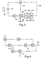
- Figure 4 shows, in greater detail than Figure 2, the arrangements for error detection at the node.
- the arrangement includes a preferred feature not incorporated in Figure 2.
- the arrangement shown in Figure 4 comprises an intermediate frequency amplifier 50 (which is part of the radio receiver 12 of ⁇ figure 2) connected to a frequency discriminator 51 (which is equivalent to discriminator 14 of Figure 2).
- the output of the frequency discriminator 51 splits into the feed-back loop (via low pass filter 53, sample-and-hold amplifier 54 and line 20 of Figure 2) and the traffic channel (line 58, low pass filter 52, regenerator 55 and line 22 of Figure 2).
- the arrangement also includes a monostable 56 between the IF amplifier 50 and the sample-and-hold amplifier 54.
- the output of the sample-and-hold amplifier is also connected to the regenerator 55.
- the incoming signal comprises a sequence of bursts, each from a different transmitter, and, because of residual errors in adjustment, each burst has a (slightly) different frequency.
- Each burst commences with preamble consisting of an alternation of "1" and "0", ie an alternation of the two keying frequencies.
- discriminator 51 receives the IF signal from the amplifier 50 and produces a baseband signal the mean D.C. voltage of which is proportional to the frequency of the input.
- the output of discriminator 51 is therefore a signal representing :-
- the data is recovered from this output in regenerator 55.
- the output of disciminator 51 also goes to smoothing circuit 53 which averages the signal thereby removing item (b) above.
- Monostable 56 is triggered by the presence of each new burst and it triggers sample-and-hold amplifier 54 towards the end of each preamble whereby the "hold” occurs when smoothing circuit 53 outputs a signal representative of the frequency of the transmitter. This signal is passed on line 20 (of Figure 2) to the feed-back loop described above and also, on line 57, to regenerator 55.
- Regenerator 55 makes 1/0 decisions depending upon whether or not the baseband input on line 58 is above or below the control value on line 57.
- Sample-and-hold amplifier 54 produces a signal which is a measure of effect (a) above, so that the decisions of the regenerator are based on (b)-(a). The operation of the invention will be further described with reference to the wave forms indicated in Figure 5.
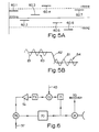
- Figure 5A illustrates the scatter of carrier frequencies due to the residual errors in the adjustment of the outstation transmitters and it is a frequency/time chart of carrier frequencies recieved by antenna 10.
- bursts 60.1, 60.2, 60.3, 60.5 and 60.7 have substantially different frequencies which differences are allowed to remain because all frequencies lie within the acceptable range. These differences appear at the output of the IF amplifier 50 and hence they affect the input to regenerator 55 which makes the task of regeneration more difficult.
- FIG. 5B which assumes the worst case and illustrates a burst 63 from an outstation transmitting at the upper band of acceptability followed by a burst 64 at the lower level.
- Trace 61 (which moderates certain features of a signal) is discontinuous because there are gaps between the bursts.
- Each burst begins with a marker preamble consisting of an alteration between the two keying frequencies so that the average frequency during the preamble is half way between the two keying frequencies.
- Trace 62 illustrates the control signal on line 52. Since this control signal is generated by sample-and-hold amplifier 54 it remains constant between sampling instants.
- the control signal has a high value so that regenerator 55 has a central level which facilitates its making correct 1/0 decisions.
- burst 64 arrives the control signal is too high.
- the gap between the bursts is detected by monostable 56 so that sample-and-hold amplifier 54 is triggered towards the end of the preamble. Therefore the trace 62 is readjusted to the centre value of trace 61. This means that the operational condition of regenerator 55 remains substantially unchanged in spite of the sudden change in the frequency of the traffic signal.
- the local frequency control loop in an outstation is illustrated in Figure 6 which indicates a preferred arrangement for transmitter 33 of Figure 3.
- the loop comprises a voltage controlled microwave oscillator 70 the output of which passes to antenna 30 via coupler 31.
- the loop also includes dielectric resonator discriminator 71 connected to adder 72 having as its second input, on line 40, the error signal from A/D converter 36.
- the other elements of the loop comprise low pass filter 73 (to remove the effect of any modulation), amplifier 74 (to give suitable loop gain) and adder 75.
- the second input to adder 75 is digital traffic on line 37.
- the output of adder 75 is connected as the control of oscillator 70.
- discriminator 71 produces an error signal which controls the frequency of oscillator 70.
- Traffic on line 37 is combined, by adder 75, with the error signal so that the oscillator 70 is controlled to produce a 2-FSK signal which is received at the node.
- the node checks the carrier frequency and returns correction signals to the outstation, and as described above, these give rise to a correction signal on line 40.
- Adder 72 combines the correction signal on line 40 with the loop signal. This adjusts the set-point of the local loop so that drift at the outstation is compensated by correction from the node.
- the system as a whole incorporates a hierarchy of measures to control or allow for instability of the transmitter at the outstations.
- the local loop at each outstation constitutes a control with the shortest response time.
- the local loop is fully capable of keeping the frequency constant for 1 ms so there is no change of frequency during a burst.
- Medium term requirements are provided by adjustment of the decision threshold which is carried out for every burst. Over a longer period of time drift at an outstation becomes unacceptably high, even with adjustment of the decision threshold, and the node changes the set point on line 40 to restore the transmitted frequency to the design value.
- the frequency control system described in this specification is intended for use in time division multi-access systems. Such systems usually have a frame period of 20 s to 200 ms, especially 100 s to 10 ms. From 2 to 2000 outstations, eg. 40 to 1000 outstations, can be accommodated in a single system although not all the outstations may be able to have simultaneous access. Burst lengths in the range 1 s to 1 ms are possible but length of 10 s to 200 s are more usual.
Landscapes
- Engineering & Computer Science (AREA)
- Computer Networks & Wireless Communication (AREA)
- Signal Processing (AREA)
- Mobile Radio Communication Systems (AREA)
- Channel Selection Circuits, Automatic Tuning Circuits (AREA)
- Radio Relay Systems (AREA)
- Digital Transmission Methods That Use Modulated Carrier Waves (AREA)
- Time-Division Multiplex Systems (AREA)
- Small-Scale Networks (AREA)
Priority Applications (1)
| Application Number | Priority Date | Filing Date | Title |
|---|---|---|---|
| AT84306112T ATE36104T1 (de) | 1983-09-07 | 1984-09-06 | Frequenzregelung fuer punkt-zu-mehrpunktfunkverbindung. |
Applications Claiming Priority (2)
| Application Number | Priority Date | Filing Date | Title |
|---|---|---|---|
| GB8323966 | 1983-09-07 | ||
| GB838323966A GB8323966D0 (en) | 1983-09-07 | 1983-09-07 | Frequency control for point-to-multipoint radio |
Publications (3)
| Publication Number | Publication Date |
|---|---|
| EP0138366A2 EP0138366A2 (en) | 1985-04-24 |
| EP0138366A3 EP0138366A3 (en) | 1985-06-19 |
| EP0138366B1 true EP0138366B1 (en) | 1988-07-27 |
Family
ID=10548427
Family Applications (1)
| Application Number | Title | Priority Date | Filing Date |
|---|---|---|---|
| EP84306112A Expired EP0138366B1 (en) | 1983-09-07 | 1984-09-06 | Frequency control for point-to-multipoint radio |
Country Status (7)
| Country | Link |
|---|---|
| US (1) | US4670889A (enExample) |
| EP (1) | EP0138366B1 (enExample) |
| JP (1) | JPS60150330A (enExample) |
| AT (1) | ATE36104T1 (enExample) |
| CA (1) | CA1232025A (enExample) |
| DE (1) | DE3473105D1 (enExample) |
| GB (1) | GB8323966D0 (enExample) |
Families Citing this family (18)
| Publication number | Priority date | Publication date | Assignee | Title |
|---|---|---|---|---|
| US4817197A (en) * | 1986-07-18 | 1989-03-28 | Nippon Telegraph And Telephone Corporation | Mobile communication apparatus |
| US5255291A (en) * | 1988-11-14 | 1993-10-19 | Stratacom, Inc. | Microprocessor based packet isochronous clocking transmission system and method |
| US5249305A (en) * | 1989-09-27 | 1993-09-28 | Motorola, Inc. | Radio frequency error detection and correction system |
| WO1991005410A1 (en) * | 1989-09-27 | 1991-04-18 | Motorola, Inc. | Method and apparatus for adjusting the frequency of a two-way radio |
| US5168575A (en) * | 1990-09-28 | 1992-12-01 | Motorola, Inc. | Demand driven wide-area radio system resource assignment method and apparatus |
| JP3269577B2 (ja) * | 1991-10-02 | 2002-03-25 | モトローラ・インコーポレイテッド | ビット誤り率検出方法 |
| US6006069A (en) * | 1994-11-28 | 1999-12-21 | Bosch Telecom Gmbh | Point-to-multipoint communications system |
| US6112056A (en) | 1995-06-07 | 2000-08-29 | Cisco Systems, Inc. | Low power, short range point-to-multipoint communications system |
| DE19613489C2 (de) * | 1996-04-04 | 2001-09-27 | Esw Extel Systems Wedel Ges Fu | Verfahren zur Übertragung von bidirektionalen Daten zwischen der Zentrale und den Teilnehmern eines Gefechtsübungszentrums |
| DE19705395C2 (de) * | 1997-02-13 | 1999-12-23 | Mikom Gmbh | Repeater |
| DE19737758A1 (de) * | 1997-08-29 | 1999-03-04 | Bosch Gmbh Robert | Verfahren zum Einstellen der Sendeträgerfrequenz in einer Teilnehmerstation eines Punkt-zu-Mehrpunkt Funkübertragungssystem |
| US6240276B1 (en) * | 1998-04-28 | 2001-05-29 | Ericsson Inc. | Compensating for errors in tuning frequency of a global positioning satellite (GPS) receiver |
| US6603958B1 (en) * | 2000-02-09 | 2003-08-05 | Nortel Networks Limited | Method and apparatus for a carrier frequency control in a wireless communication system |
| US6947748B2 (en) | 2000-12-15 | 2005-09-20 | Adaptix, Inc. | OFDMA with adaptive subcarrier-cluster configuration and selective loading |
| MXPA03005307A (es) * | 2000-12-15 | 2004-12-02 | Adaptix Inc | Comunicaciones de multiportadores con asignacion de subportadora con base en grupos. |
| KR100742580B1 (ko) * | 2002-10-30 | 2007-08-02 | 리서치 인 모션 리미티드 | 데이터 통신 서비스를 이용가능하게 하는 통신 네트워크를선택하는 방법 및 장치 |
| US7573851B2 (en) * | 2004-12-07 | 2009-08-11 | Adaptix, Inc. | Method and system for switching antenna and channel assignments in broadband wireless networks |
| KR101257066B1 (ko) * | 2005-09-06 | 2013-04-22 | 한국전자통신연구원 | 직교 주파수 분할 다중화 셀룰러 시스템에서 셀 간 간섭완화를 위한 하향 링크의 자원 분할, 할당 방법 및 송수신방법 |
Family Cites Families (10)
| Publication number | Priority date | Publication date | Assignee | Title |
|---|---|---|---|---|
| US3195047A (en) * | 1961-12-29 | 1965-07-13 | Bell Telephone Labor Inc | Frequency modulation communication system having automatic frequency deviation adjustng means |
| GB1074824A (en) * | 1965-03-05 | 1967-07-05 | British Broadcasting Corp | Improvements in and relating to the synchronising of periodic signals |
| BE754157A (fr) * | 1969-07-31 | 1971-02-01 | Siemens Ag | Montage pour la compensation de composantes parasites de tension continue lors de la demodulation de signaux de donnees binaires |
| US3654395A (en) * | 1969-10-15 | 1972-04-04 | Communications Satellite Corp | Synchronization of tdma space division satellite system |
| US4061979A (en) * | 1975-10-20 | 1977-12-06 | Digital Communications Corporation | Phase locked loop with pre-set and squelch |
| US4231114A (en) * | 1978-02-27 | 1980-10-28 | Motorola, Inc. | Synchronizing means for a two-way communication system |
| US4188582A (en) * | 1978-04-10 | 1980-02-12 | Motorola, Inc. | Simulcast transmission system having phase-locked remote transmitters |
| NL7810171A (nl) * | 1978-10-10 | 1980-04-14 | Philips Nv | Vaste post voor een systeem voor mobiele datacommuni- catie. |
| JPS57148432A (en) * | 1981-03-09 | 1982-09-13 | Nec Corp | Frequency synchronization system |
| US4520508A (en) * | 1982-12-21 | 1985-05-28 | General Instrument Corporation | Subscriber terminal for monitoring radio-frequency signal ingress into cable television systems |
-
1983
- 1983-09-07 GB GB838323966A patent/GB8323966D0/en active Pending
-
1984
- 1984-08-31 CA CA000462309A patent/CA1232025A/en not_active Expired
- 1984-09-05 US US06/647,487 patent/US4670889A/en not_active Expired - Lifetime
- 1984-09-06 AT AT84306112T patent/ATE36104T1/de not_active IP Right Cessation
- 1984-09-06 DE DE8484306112T patent/DE3473105D1/de not_active Expired
- 1984-09-06 EP EP84306112A patent/EP0138366B1/en not_active Expired
- 1984-09-07 JP JP59188764A patent/JPS60150330A/ja active Granted
Also Published As
| Publication number | Publication date |
|---|---|
| CA1232025A (en) | 1988-01-26 |
| EP0138366A2 (en) | 1985-04-24 |
| EP0138366A3 (en) | 1985-06-19 |
| GB8323966D0 (en) | 1983-10-12 |
| JPH0242255B2 (enExample) | 1990-09-21 |
| US4670889A (en) | 1987-06-02 |
| DE3473105D1 (en) | 1988-09-01 |
| ATE36104T1 (de) | 1988-08-15 |
| JPS60150330A (ja) | 1985-08-08 |
Similar Documents
| Publication | Publication Date | Title |
|---|---|---|
| EP0138366B1 (en) | Frequency control for point-to-multipoint radio | |
| US5390185A (en) | Transmission system for a combination of a main signal and an auxiliary signal | |
| US6031828A (en) | Radio communication system | |
| US4004224A (en) | Method for fade correction of communication transmission over directional radio paths | |
| US5066957A (en) | Hybrid modulation satellite communication system | |
| US4022988A (en) | Fault locating apparatus for digital transmission system | |
| CA1244153A (en) | Method of initially establishing burst acquisition in tdma satellite communications system and arrangement therefor | |
| EP0324420B1 (en) | Transponder frequency offset compensation with recurrently assigned unique words | |
| US3882456A (en) | Fault-detecting system for a multi-channel relay system | |
| CA1254313A (en) | Station of a tdma communication network capable of quickly changing communication traffic without causing an overlap between transmission bursts | |
| CA1125404A (en) | Method for generating a pseudo-signal in an error rate supervisory unit and circuit for carrying out the same | |
| US5497402A (en) | Automatic frequency control device for satellite communications ground system | |
| US4207521A (en) | System using carrier burst sequences for detecting interference signals occurring across channels of a radio link including a repeater | |
| CA2166229C (en) | Demodulator control system and a receiver capable of quickly acquiring a desired carrier wave | |
| US2798118A (en) | System for pulse-code modulation | |
| EP0935352B1 (en) | Mobile satellite communication method and system capable of carrying out carrier activation with reliability of a communication path secured | |
| JP3052518B2 (ja) | バースト信号復調装置の復調制御方法 | |
| EP0766895B1 (en) | Detection of a low level marshalling sequence | |
| USRE27202E (en) | Rf ampl | |
| JP3038877B2 (ja) | 自動周波数制御回路 | |
| CA1114904A (en) | Narrow band communication system | |
| EP0592041A1 (en) | Transmission system for a main signal and an auxiliary signal | |
| JPH01296746A (ja) | ディジタル信号の受信装置 | |
| JPS60120638A (ja) | デ−タ通信方式 | |
| JPH06334612A (ja) | 中間中継装置 |
Legal Events
| Date | Code | Title | Description |
|---|---|---|---|
| PUAI | Public reference made under article 153(3) epc to a published international application that has entered the european phase |
Free format text: ORIGINAL CODE: 0009012 |
|
| PUAL | Search report despatched |
Free format text: ORIGINAL CODE: 0009013 |
|
| AK | Designated contracting states |
Designated state(s): AT BE CH DE FR GB IT LI LU NL SE |
|
| AK | Designated contracting states |
Designated state(s): AT BE CH DE FR GB IT LI LU NL SE |
|
| 17P | Request for examination filed |
Effective date: 19850813 |
|
| 17Q | First examination report despatched |
Effective date: 19860827 |
|
| RAP1 | Party data changed (applicant data changed or rights of an application transferred) |
Owner name: BRITISH TELECOMMUNICATIONS PUBLIC LIMITED COMPANY |
|
| GRAA | (expected) grant |
Free format text: ORIGINAL CODE: 0009210 |
|
| AK | Designated contracting states |
Kind code of ref document: B1 Designated state(s): AT BE CH DE FR GB IT LI LU NL SE |
|
| REF | Corresponds to: |
Ref document number: 36104 Country of ref document: AT Date of ref document: 19880815 Kind code of ref document: T |
|
| ITF | It: translation for a ep patent filed | ||
| REF | Corresponds to: |
Ref document number: 3473105 Country of ref document: DE Date of ref document: 19880901 |
|
| ET | Fr: translation filed | ||
| PLBE | No opposition filed within time limit |
Free format text: ORIGINAL CODE: 0009261 |
|
| STAA | Information on the status of an ep patent application or granted ep patent |
Free format text: STATUS: NO OPPOSITION FILED WITHIN TIME LIMIT |
|
| 26N | No opposition filed | ||
| ITTA | It: last paid annual fee | ||
| EPTA | Lu: last paid annual fee | ||
| EAL | Se: european patent in force in sweden |
Ref document number: 84306112.8 |
|
| PGFP | Annual fee paid to national office [announced via postgrant information from national office to epo] |
Ref country code: AT Payment date: 19980813 Year of fee payment: 15 |
|
| PGFP | Annual fee paid to national office [announced via postgrant information from national office to epo] |
Ref country code: NL Payment date: 19980819 Year of fee payment: 15 |
|
| PGFP | Annual fee paid to national office [announced via postgrant information from national office to epo] |
Ref country code: CH Payment date: 19980827 Year of fee payment: 15 |
|
| PGFP | Annual fee paid to national office [announced via postgrant information from national office to epo] |
Ref country code: BE Payment date: 19980904 Year of fee payment: 15 |
|
| PGFP | Annual fee paid to national office [announced via postgrant information from national office to epo] |
Ref country code: LU Payment date: 19980908 Year of fee payment: 15 |
|
| PG25 | Lapsed in a contracting state [announced via postgrant information from national office to epo] |
Ref country code: LU Free format text: LAPSE BECAUSE OF NON-PAYMENT OF DUE FEES Effective date: 19990906 Ref country code: AT Free format text: LAPSE BECAUSE OF NON-PAYMENT OF DUE FEES Effective date: 19990906 |
|
| PG25 | Lapsed in a contracting state [announced via postgrant information from national office to epo] |
Ref country code: LI Free format text: LAPSE BECAUSE OF NON-PAYMENT OF DUE FEES Effective date: 19990930 Ref country code: CH Free format text: LAPSE BECAUSE OF NON-PAYMENT OF DUE FEES Effective date: 19990930 Ref country code: BE Free format text: LAPSE BECAUSE OF NON-PAYMENT OF DUE FEES Effective date: 19990930 |
|
| BERE | Be: lapsed |
Owner name: BRITISH TELECOMMUNICATIONS P.L.C. Effective date: 19990930 |
|
| PG25 | Lapsed in a contracting state [announced via postgrant information from national office to epo] |
Ref country code: NL Free format text: LAPSE BECAUSE OF NON-PAYMENT OF DUE FEES Effective date: 20000401 |
|
| REG | Reference to a national code |
Ref country code: CH Ref legal event code: PL |
|
| NLV4 | Nl: lapsed or anulled due to non-payment of the annual fee |
Effective date: 20000401 |
|
| PGFP | Annual fee paid to national office [announced via postgrant information from national office to epo] |
Ref country code: FR Payment date: 20010813 Year of fee payment: 18 |
|
| PGFP | Annual fee paid to national office [announced via postgrant information from national office to epo] |
Ref country code: SE Payment date: 20010817 Year of fee payment: 18 Ref country code: GB Payment date: 20010817 Year of fee payment: 18 |
|
| PGFP | Annual fee paid to national office [announced via postgrant information from national office to epo] |
Ref country code: DE Payment date: 20010820 Year of fee payment: 18 |
|
| REG | Reference to a national code |
Ref country code: GB Ref legal event code: IF02 |
|
| PG25 | Lapsed in a contracting state [announced via postgrant information from national office to epo] |
Ref country code: GB Free format text: LAPSE BECAUSE OF NON-PAYMENT OF DUE FEES Effective date: 20020906 |
|
| PG25 | Lapsed in a contracting state [announced via postgrant information from national office to epo] |
Ref country code: SE Free format text: LAPSE BECAUSE OF NON-PAYMENT OF DUE FEES Effective date: 20020907 |
|
| PG25 | Lapsed in a contracting state [announced via postgrant information from national office to epo] |
Ref country code: DE Free format text: LAPSE BECAUSE OF NON-PAYMENT OF DUE FEES Effective date: 20030401 |
|
| GBPC | Gb: european patent ceased through non-payment of renewal fee |
Effective date: 20020906 |
|
| EUG | Se: european patent has lapsed | ||
| PG25 | Lapsed in a contracting state [announced via postgrant information from national office to epo] |
Ref country code: FR Free format text: LAPSE BECAUSE OF NON-PAYMENT OF DUE FEES Effective date: 20030603 |
|
| REG | Reference to a national code |
Ref country code: FR Ref legal event code: ST |