EP0136624A2 - Tragvorrichtung für Kamera - Google Patents
Tragvorrichtung für Kamera Download PDFInfo
- Publication number
- EP0136624A2 EP0136624A2 EP84111189A EP84111189A EP0136624A2 EP 0136624 A2 EP0136624 A2 EP 0136624A2 EP 84111189 A EP84111189 A EP 84111189A EP 84111189 A EP84111189 A EP 84111189A EP 0136624 A2 EP0136624 A2 EP 0136624A2
- Authority
- EP
- European Patent Office
- Prior art keywords
- pipe
- clamp
- camera holder
- legs
- camera
- Prior art date
- Legal status (The legal status is an assumption and is not a legal conclusion. Google has not performed a legal analysis and makes no representation as to the accuracy of the status listed.)
- Withdrawn
Links
Images


Classifications
-
- G—PHYSICS
- G03—PHOTOGRAPHY; CINEMATOGRAPHY; ANALOGOUS TECHNIQUES USING WAVES OTHER THAN OPTICAL WAVES; ELECTROGRAPHY; HOLOGRAPHY
- G03B—APPARATUS OR ARRANGEMENTS FOR TAKING PHOTOGRAPHS OR FOR PROJECTING OR VIEWING THEM; APPARATUS OR ARRANGEMENTS EMPLOYING ANALOGOUS TECHNIQUES USING WAVES OTHER THAN OPTICAL WAVES; ACCESSORIES THEREFOR
- G03B17/00—Details of cameras or camera bodies; Accessories therefor
- G03B17/56—Accessories
-
- F—MECHANICAL ENGINEERING; LIGHTING; HEATING; WEAPONS; BLASTING
- F16—ENGINEERING ELEMENTS AND UNITS; GENERAL MEASURES FOR PRODUCING AND MAINTAINING EFFECTIVE FUNCTIONING OF MACHINES OR INSTALLATIONS; THERMAL INSULATION IN GENERAL
- F16M—FRAMES, CASINGS OR BEDS OF ENGINES, MACHINES OR APPARATUS, NOT SPECIFIC TO ENGINES, MACHINES OR APPARATUS PROVIDED FOR ELSEWHERE; STANDS; SUPPORTS
- F16M11/00—Stands or trestles as supports for apparatus or articles placed thereon ; Stands for scientific apparatus such as gravitational force meters
- F16M11/02—Heads
- F16M11/04—Means for attachment of apparatus; Means allowing adjustment of the apparatus relatively to the stand
- F16M11/06—Means for attachment of apparatus; Means allowing adjustment of the apparatus relatively to the stand allowing pivoting
- F16M11/10—Means for attachment of apparatus; Means allowing adjustment of the apparatus relatively to the stand allowing pivoting around a horizontal axis
-
- F—MECHANICAL ENGINEERING; LIGHTING; HEATING; WEAPONS; BLASTING
- F16—ENGINEERING ELEMENTS AND UNITS; GENERAL MEASURES FOR PRODUCING AND MAINTAINING EFFECTIVE FUNCTIONING OF MACHINES OR INSTALLATIONS; THERMAL INSULATION IN GENERAL
- F16M—FRAMES, CASINGS OR BEDS OF ENGINES, MACHINES OR APPARATUS, NOT SPECIFIC TO ENGINES, MACHINES OR APPARATUS PROVIDED FOR ELSEWHERE; STANDS; SUPPORTS
- F16M11/00—Stands or trestles as supports for apparatus or articles placed thereon ; Stands for scientific apparatus such as gravitational force meters
- F16M11/20—Undercarriages with or without wheels
- F16M11/2007—Undercarriages with or without wheels comprising means allowing pivoting adjustment
- F16M11/2014—Undercarriages with or without wheels comprising means allowing pivoting adjustment around a vertical axis
-
- F—MECHANICAL ENGINEERING; LIGHTING; HEATING; WEAPONS; BLASTING
- F16—ENGINEERING ELEMENTS AND UNITS; GENERAL MEASURES FOR PRODUCING AND MAINTAINING EFFECTIVE FUNCTIONING OF MACHINES OR INSTALLATIONS; THERMAL INSULATION IN GENERAL
- F16M—FRAMES, CASINGS OR BEDS OF ENGINES, MACHINES OR APPARATUS, NOT SPECIFIC TO ENGINES, MACHINES OR APPARATUS PROVIDED FOR ELSEWHERE; STANDS; SUPPORTS
- F16M11/00—Stands or trestles as supports for apparatus or articles placed thereon ; Stands for scientific apparatus such as gravitational force meters
- F16M11/20—Undercarriages with or without wheels
- F16M11/2092—Undercarriages with or without wheels comprising means allowing depth adjustment, i.e. forward-backward translation of the head relatively to the undercarriage
-
- F—MECHANICAL ENGINEERING; LIGHTING; HEATING; WEAPONS; BLASTING
- F16—ENGINEERING ELEMENTS AND UNITS; GENERAL MEASURES FOR PRODUCING AND MAINTAINING EFFECTIVE FUNCTIONING OF MACHINES OR INSTALLATIONS; THERMAL INSULATION IN GENERAL
- F16M—FRAMES, CASINGS OR BEDS OF ENGINES, MACHINES OR APPARATUS, NOT SPECIFIC TO ENGINES, MACHINES OR APPARATUS PROVIDED FOR ELSEWHERE; STANDS; SUPPORTS
- F16M13/00—Other supports for positioning apparatus or articles; Means for steadying hand-held apparatus or articles
-
- F—MECHANICAL ENGINEERING; LIGHTING; HEATING; WEAPONS; BLASTING
- F16—ENGINEERING ELEMENTS AND UNITS; GENERAL MEASURES FOR PRODUCING AND MAINTAINING EFFECTIVE FUNCTIONING OF MACHINES OR INSTALLATIONS; THERMAL INSULATION IN GENERAL
- F16M—FRAMES, CASINGS OR BEDS OF ENGINES, MACHINES OR APPARATUS, NOT SPECIFIC TO ENGINES, MACHINES OR APPARATUS PROVIDED FOR ELSEWHERE; STANDS; SUPPORTS
- F16M2200/00—Details of stands or supports
- F16M2200/02—Locking means
Definitions
- the present invention relates to a camera holder and, more particularly, to a holder for a television (TV) camera or the like which selectively serves as a clamp, a breast support arm, a tripod and a grip.
- TV television
- a camera holder having multiple functions of the present invention comprises a first pipe provided with camera mount means at one end thereof, a second pipe telescoped in the first pipe from the other end of the first pipe to be slidable along an axis of the first pipe, pipe fastening means for fastening the second pipe telescoped in the second pipe at a desired position, a first clamp seat rigidly mounted on the second pipe, a second clamp seat mounted on an outer periphery of the second pipe to be slidable along and rotatable about an axis of the second pipe, the second clamp seat being provided with a rotatable arm having locking means, a clamp fastening member for fastening the second clamp after positioning the second clamp relative to the second pipe, and legs for cooperating with the rotatable arm of the second clamp to constitute a tripod, the legs being nested in the second pipe when out of use and pulled out when in use.
- a holder for holding a TV camera or like camera selectively serves as a clamp, a breast support arm, a tripod and a grip.
- the camera is mounted on one end of a first pipe, while a second pipe is telescoped in the first pipe to be slidable therealong.
- First and second clamp seats are mounted on the second pipe.
- the second clamp seat is provided with a rotatable arm which is slidable along and rotatable about the axis of the second pipe.
- the clamp, breast support arm or grip function is attained by rotating the rotatable arm to a predetermined fixing position and moving the second clamp to a predetermined fixing position on the second pipe.
- Two legs are nested in the second pipe such that when the tripod function is desired the legs are pulled out from the second pipe, opened by a predetermined angle away from each other, and fixed in the opened position.
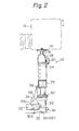
- a camera holder in accordance with the present invention is shown and generally designated by the reference numeral 10.
- a TV camera 12 is detachably mounted on a camera mount 14 of the camera holder 10.
- the camera mount 14 has a shaft 16 which is rotatably mounted in a free pan head 18 and adjusted in position by a pan head fastening screw 20.
- a pipe 22 is positioned below the pan head 18, while a grip portion 24 made of rubber or like material is fit on the outer periphery of the pipe 22.
- the pipe 22 carries a tubular pipe fastening ring 26 in a lower end portion thereof.
- the ring 26 is adapted to fasten the pipe 22 to another pipe 30 in cooperation with a spacer 28, which is positioned radially inwardly of the ring 26.
- the pipe 30 is telescoped in the pipe 22 and firmly tied to the pipe 22 by the ring 28.
- a clamp seat 32 is rigidly mounted on a lower end portion of the pipe 30. Also arranged on the pipe 30 is another clamp seat 34 having a rotatable arm 36 therewith. The arm 36 is rotatable about a dash-and-dot line in Fig. 1 and provided with means for locking the arm in a predetermined angular position.
- the clamp seat 34 unlike the clamp seat 32, is freely movable along both the axis and the circumference of the pipe 30.
- the clamp seat 34 is formed with a thread 38 in the outer periphery of its upper end portion.
- a clamp fastening ring 40 is formed with a thread 42 in the inner periphery of its lower end, the thread 42 being engageable with the thread 38.
- the position of the calmp seat 34 in the axial direction of the pipe 30 is adjustable by rotating the clamp fastening ring 40.
- the pipe 30 may be provided with a slide channel along its axis, and the clamp seat 34 with a lug which is biased by a spring or the like into the slide channeL
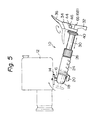
- the interengaged lug and slide channel will prevent the clamp seat 34 from rotating in positions of the pipe 30 other than the lower end, e. g. , a position shown in Fig. 2; at the lower end, e. g. , a position shown in Fig. 5, the lug will be pushed back against the spring to render the calmp seat 34 rotatable. Such will facilitate handling of the clamp seat 34.
- the clamp seats 32 and 34 are provided with a mechanism which locks them to each other when the clamp seat 34 is rotated to a position shown in Figs. 5-7.
- the locking mechanism may comprise, as illustrated, a lug 44 protruding from the clamp seat 32 and a lug 46 protruding from the clamp seat 34.
- the lugs 44 and 46 lock to each other to prevent the clamp seat 34 from moving along the axis of the pipe 30.
- a snapping mechanism may be employed which limits the rotation of the clamp seat 34 along the circumference of the pipe 30 in the above-described position.
- a pair of legs 48 and 50 are nested in the pipe 30 to serve as the legs of a tripod.
- the legs 48 and 50 can be pulled out from the pipe 30 and, after being opened away from each other by a predetermined angle in a predetermined direction, locked in position as will be described.
- the camera holder 10 in accordance with the present invention is usable in various manners, or modes, as will be described.
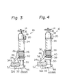
- the camera holder 10 is shown in a condition for serving as a clamp.
- the pipes 22 and 30 are made free relative to each other by loosening the pipe fastening ring 26.
- the pipe 22, or grip portion 24, and the like are lowered and, then, the pipe fastening ring 26 is tightened to fasten the pipes 22 and 30 firmly to each other (Fig. 3). Even in this position, the clamp seats 32 and 34 have clamped the solid object 52 therebetween, but not with a desired magnitude of force.
- the clamp fastening ring 40 is rotated in a predetermined direction.
- the camera holder 10 is used as a clamp, it is possible to freely determine a clamp width by moving the pipe 30 or 22, that is, the camera holder 10 can clamp any desired solid object if the pipe 30 is provided with a certain length. Moreover, when not used as a clamp, the camera holder 10 can be put together in a compact and handy configuration by nesting the pipe 30 in the pipe 22.
- the clamp seat 34 is moved to the lower end of the pipe 30 and, then, rotated until the clamp seat 34 becomes locked to the clamp seat 32. Thereafter, the rotatable arm 36 associated with the clamp seat 34 is rotated 180 degrees, and the relative position of the pipes 22 and 30, i. e. , the length of the pipe 30 outside the pipe 30, is adjusted as desired. In this position, the camera holder 10 is usable as a breast support arm in an optimum configuration for a user.
- the legs 48 and 50 are pulled out from the pipe 30 and opened away from each other. Then, the legs 48 and 50 constitute a tripod in combination with the rotatable arm 36.
- the length of the pipe 30 outside the pipe 22 is adjustable to locate the camera at a desired level.
- the camera holder 10 functions as a clamp, a breast support arm or a tripod in an optimum way in dependence upon the position of the pipe 30 relative to the pipe 22.
- a pair of legs 54 and 56 each having a generally U-shaped cross-section and constituting a body portion are nested in the pipe 30 in the same manner as the legs 48 and 50.
- Legs 54a and 56a each having, for example, a rectangular cross-section and constituting a fold portion are foldably connected to the legs 54 and 56 by pins 58 and 60, respectively.
- the legs 54a and 56a are rotated 180 degrees about the pins 58 and 60, respectively, they are folded into their associated legs 54 and 56 as shown in Fig. 11.
- the legs 54a and 56a are unfolded out of the associated legs 54 and 56 about the pins 58 and 60, they become aligned with the legs 54 and 56, respectively, as shown in Fig. 10.
- each of the foldaway legs nested in the pipe 30 is shown to have one articulation, it may be provided with two or more articulations if desired.
- the legs 54 and 56 Adjacent to their base ends, as shown in Figs. 11 through 13, the legs 54 and 56 respectively are formed with notched holes 62 and 64 for extra strength and fitness.
- the bottom of the clamp seat 32 is provided with lugs 66 and 68 a shape and position of each is corresponding to the notched holes 62 and 64, respectively.
- the lug 66 protrudes into the leg 54 through the notch 62 as shown in Figs. 11 and 12 so as to push the leg 54a a little out of the leg 54. So pushed out by the lug 66, the leg 54a will be easily manipulated 180 degrees to its unfolded position.
- the clamp seat 34 is positioned in the same manner as in Fig. 5 and the two legs 54 and 56 are pulled out from the pipe 30. Then, as shown in Figs. 10 and 11, the legs 54 and 56 are opened whereafter the legs 54a and 56a are fully unfolded utilizing their free ends which have been pushed out a little as described.
- the legs 54 and 54a and the legs 56 and 56a in the unfolded position cooperate with the rotatable arm 36 to implement the function of a tripod.
- the length of the pipe 30 pulled out from the pipe 22 is adjustable to set up a desired height of the camera.
- each articulated leg assembly may be increased even through if the pipe 30, for example, is relatively short.
- the longer legs will offer greater stability in working as a tripod.
- the respective articulated legs become very short when folded up for storage, they can be accommodated in the pipe 30 even if the latter is relatively short and, therefore, the whole holder assembly assumes a compact configuration while out of use.
- leg 54 and 56 In the modification shown and described, fully opening the legs 54 and 56 causes their associated legs 54a and 56a to be pushed thereoutof. Such allows the legs 54a and 56a to be manipulated smoothly out of the legs 54 and 56, respectively.
- Another advantage attainable with the lugs 66 and 68 and the holes 62 and 64 is that the legs 54 and 56 are secured thus preventing lateral dislocation and, thereby, serve with greater stability as a tripod, while attaining greater mechanical strength.
- the present invention provides a camera holder which selectively serves the function of a clamp, that of a breast support arm, that of a tripod, and that of a grip, has a compact and handy configurion when out of use, and features easy use.
- legs of the camera holder can be fully nested in a pipe even if the latter is relatively short, and become very long when in an unfolded position. This allows the camera holder to be put together compact, to achieve stability during use, and to free its legs from unsteadiness.
- opening a first leg causes a second leg associated therewith to be partly opened, making the manipulation for opening the second leg very smooth.
Landscapes
- Engineering & Computer Science (AREA)
- General Engineering & Computer Science (AREA)
- Mechanical Engineering (AREA)
- Physics & Mathematics (AREA)
- General Physics & Mathematics (AREA)
- Accessories Of Cameras (AREA)
- Studio Devices (AREA)
Applications Claiming Priority (2)
| Application Number | Priority Date | Filing Date | Title |
|---|---|---|---|
| JP1983150574U JPS6059899U (ja) | 1983-09-30 | 1983-09-30 | 三脚 |
| JP150574/83U | 1983-09-30 |
Publications (2)
| Publication Number | Publication Date |
|---|---|
| EP0136624A2 true EP0136624A2 (de) | 1985-04-10 |
| EP0136624A3 EP0136624A3 (de) | 1986-10-08 |
Family
ID=15499858
Family Applications (1)
| Application Number | Title | Priority Date | Filing Date |
|---|---|---|---|
| EP84111189A Withdrawn EP0136624A3 (de) | 1983-09-30 | 1984-09-19 | Tragvorrichtung für Kamera |
Country Status (5)
| Country | Link |
|---|---|
| US (1) | US4640481A (de) |
| EP (1) | EP0136624A3 (de) |
| JP (1) | JPS6059899U (de) |
| KR (1) | KR860003134Y1 (de) |
| DE (1) | DE136624T1 (de) |
Cited By (4)
| Publication number | Priority date | Publication date | Assignee | Title |
|---|---|---|---|---|
| FR2623842A1 (fr) * | 1987-11-30 | 1989-06-02 | Faure Fils Ste Cale Ets | Dispositif de reglage en sens vertical pour paumelle et paumelle equipee de ce dispositif |
| GB2236032A (en) * | 1989-06-27 | 1991-03-20 | Minolta Camera Kk | Infra red image pick-up apparatus |
| GB2269023A (en) * | 1992-07-02 | 1994-01-26 | Sharpe S Of Aberdeen Limited | Optical instrument support stabilised against user's body |
| WO2021258652A1 (zh) * | 2020-06-22 | 2021-12-30 | 深圳市大疆创新科技有限公司 | 云台及拍摄装置 |
Families Citing this family (36)
| Publication number | Priority date | Publication date | Assignee | Title |
|---|---|---|---|---|
| IT218035Z2 (it) * | 1986-12-23 | 1992-03-30 | Bolondi Ivano | Supporto di sicurezza brandeggiabile,in particolare per strumenti ottici e fotografici |
| DE3920128C2 (de) * | 1988-06-20 | 1997-07-17 | Fuji Photo Film Co Ltd | Videokamera |
| US5098182A (en) * | 1988-09-22 | 1992-03-24 | Brown Garrett W | Stabilized equipment support, primarily for use with light-weight cameras |
| JPH05119392A (ja) * | 1991-05-15 | 1993-05-18 | Sony Corp | カメラ等の支持脚 |
| USD349915S (en) | 1992-08-17 | 1994-08-23 | Hama Hamaphot Kg Hanke & Thomas | Tripod |
| GB2273521B (en) * | 1992-12-19 | 1995-07-19 | David Calvert | A mounting |
| USD357031S (en) | 1993-05-28 | 1995-04-04 | Hama Hamaphot Kg | Incliner |
| US5585849A (en) * | 1993-07-21 | 1996-12-17 | Robalino; Manuel | Auxiliary handle for portable video camera |
| US5497214A (en) * | 1994-07-11 | 1996-03-05 | Labree; Michael A. | Camera mount |
| US6076978A (en) * | 1998-08-07 | 2000-06-20 | Mcilvenna; Kevin Lee | Remote photography device |
| US6244759B1 (en) * | 1999-05-10 | 2001-06-12 | Rob Russo | Adjustable camera support |
| USD487904S1 (en) * | 2002-04-11 | 2004-03-30 | Polyvision Corporation | Camera arm |
| US7232265B1 (en) * | 2003-06-16 | 2007-06-19 | Price Roger W | Seat with articulating camera support |
| US8069603B2 (en) * | 2003-12-02 | 2011-12-06 | Grip Pod Systems, Llc | Canting vertical fore grip with bipod |
| US7111424B1 (en) | 2003-12-02 | 2006-09-26 | Moody Joseph R | Fore grip with bipod |
| US20060233544A1 (en) * | 2005-04-11 | 2006-10-19 | Roman Coppola | Bipod platform system for a camera |
| PL1877859T3 (pl) * | 2005-04-15 | 2013-03-29 | Brown Garrett W | Składająca i regulująca zawiasa do stabilizowanego wspornika sprzętu |
| US7563038B2 (en) * | 2005-06-20 | 2009-07-21 | Lino Manfrotto + Co. S.P.A. | Support for a camcorder |
| EP1736700B1 (de) * | 2005-06-23 | 2012-09-12 | General Electric Company | Klemmvorrichtung für Patientsbildschirmeinheit |
| CN100465769C (zh) * | 2005-08-09 | 2009-03-04 | 杨永坚 | 带双卡钳锁定的连接器的相机云台 |
| USD580474S1 (en) * | 2007-10-19 | 2008-11-11 | Tony Lee | Storage handle for a camera |
| US10831093B1 (en) * | 2008-05-19 | 2020-11-10 | Spatial Cam Llc | Focus control for a plurality of cameras in a smartphone |
| US9171221B2 (en) * | 2010-07-18 | 2015-10-27 | Spatial Cam Llc | Camera to track an object |
| US20110098083A1 (en) * | 2008-05-19 | 2011-04-28 | Peter Lablans | Large, Ultra-Thin And Ultra-Light Connectable Display For A Computing Device |
| WO2014107574A1 (en) | 2013-01-04 | 2014-07-10 | Brown Garrett W | Folding image stabilizer |
| US8770539B1 (en) * | 2013-02-05 | 2014-07-08 | Kevin Hsu | Electronic gadget holder for automobiles and tripods |
| US9483075B2 (en) * | 2013-05-14 | 2016-11-01 | Paul Liniger | Handheld mount and stand assembly for portable electronic devices |
| US9736376B1 (en) | 2014-04-03 | 2017-08-15 | The Tiffen Company, Llc | Tilt head, camera stage, multi-post monitor mount and camera stabilizer encompassing the same |
| US9709356B1 (en) * | 2014-05-06 | 2017-07-18 | Tja Design Llc | Multi-axis firearm foregrip |
| USD790652S1 (en) | 2016-03-08 | 2017-06-27 | Grip Pod Systems International, Llc | Firearm bipod |
| US10168119B2 (en) | 2016-12-23 | 2019-01-01 | Magpul Industries Corp. | Firearm bipod |
| US10161706B2 (en) * | 2016-12-23 | 2018-12-25 | Magpul Industries Corp. | Firearm bipod |
| US11215208B2 (en) | 2017-11-24 | 2022-01-04 | Xiaoming Chen | Positioning locking mechanism of rotational member |
| CN207601483U (zh) * | 2017-11-24 | 2018-07-10 | 陈小鸣 | 一种双向快速锁紧装置 |
| US11218632B2 (en) * | 2019-11-01 | 2022-01-04 | Qualcomm Incorporated | Retractable panoramic camera module |
| US11021215B1 (en) * | 2020-07-08 | 2021-06-01 | Ideal Tool And Manufacturing | Fully telescoping device mount |
Family Cites Families (11)
| Publication number | Priority date | Publication date | Assignee | Title |
|---|---|---|---|---|
| DE1050557B (de) * | 1959-02-12 | Neuburg/Donau Robert Widmer | Kombmationsstativ | |
| FR35082E (de) * | 1929-12-10 | |||
| GB470790A (en) * | 1936-02-21 | 1937-08-23 | Noel Pemberton Billing | Improvements in or relating to collapsable tripod stands |
| US2195366A (en) * | 1938-04-21 | 1940-03-26 | William H Haigh | Portable tool tray |
| DE730340C (de) * | 1939-07-30 | 1943-01-11 | Leitz Ernst Gmbh | Kleinstativ fuer optische Apparate |
| DE1062943B (de) * | 1956-09-22 | 1959-08-06 | Emil Funke | Stativ |
| GB913550A (en) * | 1958-12-31 | 1962-12-19 | John Archibald Mckenzie | An improved support for photographic cameras |
| US3908945A (en) * | 1974-02-21 | 1975-09-30 | Herbert D Shapiro | Portable camera mounting apparatus |
| US4121799A (en) * | 1976-12-30 | 1978-10-24 | Kawazoe Michio | Tripod for a camera |
| DE2902419C3 (de) * | 1979-01-23 | 1981-07-02 | Cullmann Handelsgesellschaft für Verbrauchsgüter mbH, 8506 Langenzenn | Stativ für optische Geräte, insbesondere Kameras |
| US4285485A (en) * | 1979-07-23 | 1981-08-25 | Burke Willard E | Retractable sonar sensing system |
-
1983
- 1983-09-30 JP JP1983150574U patent/JPS6059899U/ja active Granted
-
1984
- 1984-09-17 US US06/651,547 patent/US4640481A/en not_active Expired - Fee Related
- 1984-09-18 KR KR2019840009156U patent/KR860003134Y1/ko not_active Expired
- 1984-09-19 DE DE198484111189T patent/DE136624T1/de active Pending
- 1984-09-19 EP EP84111189A patent/EP0136624A3/de not_active Withdrawn
Cited By (7)
| Publication number | Priority date | Publication date | Assignee | Title |
|---|---|---|---|---|
| FR2623842A1 (fr) * | 1987-11-30 | 1989-06-02 | Faure Fils Ste Cale Ets | Dispositif de reglage en sens vertical pour paumelle et paumelle equipee de ce dispositif |
| EP0319388A1 (de) * | 1987-11-30 | 1989-06-07 | Ste Commerciale Des Ets Faure & Ses Fils Ferronnerie Du Centre | Höhenverstellvorrichtung für Bänder und Band, ausgerüstet mit dieser Vorrichtung |
| GB2236032A (en) * | 1989-06-27 | 1991-03-20 | Minolta Camera Kk | Infra red image pick-up apparatus |
| US5159198A (en) * | 1989-06-27 | 1992-10-27 | Minolta Camera Kabushiki Kaisha | Infrared image pick-up apparatus |
| GB2236032B (en) * | 1989-06-27 | 1994-04-06 | Minolta Camera Kk | Infrared image pick-up apparatus |
| GB2269023A (en) * | 1992-07-02 | 1994-01-26 | Sharpe S Of Aberdeen Limited | Optical instrument support stabilised against user's body |
| WO2021258652A1 (zh) * | 2020-06-22 | 2021-12-30 | 深圳市大疆创新科技有限公司 | 云台及拍摄装置 |
Also Published As
| Publication number | Publication date |
|---|---|
| US4640481A (en) | 1987-02-03 |
| JPS6244234Y2 (de) | 1987-11-19 |
| EP0136624A3 (de) | 1986-10-08 |
| DE136624T1 (de) | 1985-11-21 |
| JPS6059899U (ja) | 1985-04-25 |
| KR850009643U (ko) | 1985-12-05 |
| KR860003134Y1 (ko) | 1986-11-08 |
Similar Documents
| Publication | Publication Date | Title |
|---|---|---|
| US4640481A (en) | Camera holder | |
| US5275364A (en) | Pole-type camera support | |
| US7395561B2 (en) | Support device | |
| US4596484A (en) | Lock for telescoping tubular support | |
| US6334400B1 (en) | Foldable table | |
| US20230175283A1 (en) | Canopy engagement device and canopy with the canopy engagement device | |
| US4169687A (en) | Lock for extendable leg assembly | |
| EP0598718B1 (de) | Dreibeinstativ | |
| JPS5930593A (ja) | 解除可能係止装置及び入れ子式装置 | |
| US5725187A (en) | Camera mount device | |
| US4214739A (en) | Fly tying device | |
| EP0413507A1 (de) | Zwischen gefalltetem und errichtetem Zustand feststellbares Zelt | |
| CN109764234A (zh) | 稳定器折叠结构及手持式稳定器 | |
| US20080223261A1 (en) | Table assembly | |
| US5284313A (en) | Mounting system | |
| JPS59500138A (ja) | 改良された調整自在なブレ−スまたはプロツプ | |
| CN109827056A (zh) | 稳定器折叠结构及手持式稳定器 | |
| CA2116792A1 (en) | Union for sensor mounting assembly | |
| WO1998025038A2 (en) | Tilt adjustment device for a boom stand | |
| US4270239A (en) | Interlock support structure | |
| EP0618375B1 (de) | Verbindungsvorrichtung für die lösbare Verbindung von zwei Elementen | |
| US7849848B2 (en) | Erectable and stowable decorative firebowl and stand assembly | |
| GB2313029A (en) | Fishing rod support means | |
| CN221357231U (zh) | 一种支撑喉镜动物喉解剖的固定装置 | |
| JP3563120B2 (ja) | 三脚の開脚度調節装置 |
Legal Events
| Date | Code | Title | Description |
|---|---|---|---|
| PUAI | Public reference made under article 153(3) epc to a published international application that has entered the european phase |
Free format text: ORIGINAL CODE: 0009012 |
|
| AK | Designated contracting states |
Designated state(s): DE FR GB |
|
| EL | Fr: translation of claims filed | ||
| DET | De: translation of patent claims | ||
| PUAL | Search report despatched |
Free format text: ORIGINAL CODE: 0009013 |
|
| AK | Designated contracting states |
Kind code of ref document: A3 Designated state(s): DE FR GB |
|
| STAA | Information on the status of an ep patent application or granted ep patent |
Free format text: STATUS: THE APPLICATION IS DEEMED TO BE WITHDRAWN |
|
| 18D | Application deemed to be withdrawn |
Effective date: 19870409 |
|
| RIN1 | Information on inventor provided before grant (corrected) |
Inventor name: KOHNO, TERUO |