EP0136330B1 - Retroviseur externe de securite - Google Patents
Retroviseur externe de securite Download PDFInfo
- Publication number
- EP0136330B1 EP0136330B1 EP84901044A EP84901044A EP0136330B1 EP 0136330 B1 EP0136330 B1 EP 0136330B1 EP 84901044 A EP84901044 A EP 84901044A EP 84901044 A EP84901044 A EP 84901044A EP 0136330 B1 EP0136330 B1 EP 0136330B1
- Authority
- EP
- European Patent Office
- Prior art keywords
- mirror
- vehicle
- driver
- safety
- zone
- Prior art date
- Legal status (The legal status is an assumption and is not a legal conclusion. Google has not performed a legal analysis and makes no representation as to the accuracy of the status listed.)
- Expired
Links
- 239000011521 glass Substances 0.000 claims abstract description 10
- 238000010276 construction Methods 0.000 abstract description 9
- 239000004033 plastic Substances 0.000 abstract description 7
- 239000005336 safety glass Substances 0.000 abstract description 4
- 238000000034 method Methods 0.000 description 5
- 210000003128 head Anatomy 0.000 description 4
- 239000002650 laminated plastic Substances 0.000 description 4
- 230000004313 glare Effects 0.000 description 3
- 239000002985 plastic film Substances 0.000 description 2
- 230000000007 visual effect Effects 0.000 description 2
- 239000003086 colorant Substances 0.000 description 1
- 238000002474 experimental method Methods 0.000 description 1
- 238000009434 installation Methods 0.000 description 1
- 238000000926 separation method Methods 0.000 description 1
- 229910052709 silver Inorganic materials 0.000 description 1
- 239000004332 silver Substances 0.000 description 1
Images
Classifications
-
- G—PHYSICS
- G02—OPTICS
- G02B—OPTICAL ELEMENTS, SYSTEMS OR APPARATUS
- G02B5/00—Optical elements other than lenses
- G02B5/08—Mirrors
-
- B—PERFORMING OPERATIONS; TRANSPORTING
- B60—VEHICLES IN GENERAL
- B60R—VEHICLES, VEHICLE FITTINGS, OR VEHICLE PARTS, NOT OTHERWISE PROVIDED FOR
- B60R1/00—Optical viewing arrangements; Real-time viewing arrangements for drivers or passengers using optical image capturing systems, e.g. cameras or video systems specially adapted for use in or on vehicles
- B60R1/02—Rear-view mirror arrangements
Definitions
- the present invention relates generally to the field of side view mirrors for motor vehicles, and more particularly, is directed to an improved side view mirror that is especially designed to facilitate rapid determination of a safe passing distance in front of an overtaking vehicle.
- most vehicles are equipped with both a rear view mirror and side view mirror, which mirrors are so installed and positioned in and about the vehicle as to permit the driver to observe rearward traffic conditions by merely shifting his eyes to view the mirrors without completely turning his head.
- the side view mirror is most advantageous to determine whether the passing lane is sufficiently clear from the rear to allow the motorist to pull into the passing lane for passing a slower moving vehicle in front.
- US-A-2,871,754 discloses according to the preamble of claim 1 a safety rearview mirror for a vehicle, said mirror comprising a frame and a demarcated reflecting glass surface.
- the present invention is characterised in that the mirror is a side mount mirror demarcated into an outboard zone of a first colour and an inboard zone of a second colour, whereby in use an image of a trailing vehicle impinging upon the colour of the outboard zone indicates that passing manoevers are unsafe.
- the present invention thus relates generally to the field of automobile side view mirrors, and more particularly, is directed to a vehicle side view mirror including easily read "safe” and “non-safe” zones whereby, by observing rearwardly positioned traffic in the side view mirror, a driver can speedily and accurately determine whether adequate clearance is available to him for passing purposes.
- the improved safety mirror of the present invention includes a line of demarcation upon the face of the mirror which is so positioned as to delineate the safe passing zone from the danger zone. As soon as any part of a trailing vehicle appears in the danger zone, the driver will immediately know that there is insufficient clearance between his vehicle and the rearwardly positioned vehicle and therefore, that it is unsfe to attempt to pass a slower moving, forwardly positioned vehicle.
- the improved safety mirror of the present invention is fabricated of safety glass construction and includes a laminated sandwich-like construction having top and bottom glass layers with a suitable plastic laminate intermediate the top and bottom glass layers.
- the glass layers and the intermediate plastic sheet are bound together in known manner to provide a suitable safety glass construction.
- the portion of the plastic sheet which lies within the so-called "safe" or passing area is fabricated of yellow or amber colored plastic so that the driver, when his quick glance observes a rearwardly positioned automobile in the yellow area, will automatically and quickly determine that the rearwardly positioned vehicle is at a nominally safe distance behind to allow him to enter into the passing lane.
- a green tint has not been chosen because some drivers may interpret this color to mean absolute safety, which may not always be the cause when considering such variables as speed, highway conditions, weather and the like.
- the "unsafe" or no-passing portion of the safety mirror is preferably fabricated of red plastic, whereby an image in the "no-passing" portion of the mirror will appear red to the view. Accordingly, as soon as any portion of the image of an overtaking vehicle is viewed by the driver to the left of the demarcation line, that is, within the red colored area, the driver will immediately know that is would be unsafe for him to attempt to pass any forwardly positioned vehicles.
- the red color is the standard highway and traffic symbol which is universally employed to indicate stop or danger, much in the manner of the usual traffic light colors employed generally throughout most areas of the world. The amber or yellow color has been chosen as a standard recognized symbol which is generally or universally employed to indicate caution.
- the optimum position of theline of demarcation has been determined to be approximately two- thirds of the width of the mirror away from the driver's side of the vehicle.
- a vehicle viewed in the yellow or "caution" area indicates a distance of approximately two or two and one-half car lengths between the vehicle being driven and an overtaking vehicle.
- this may be a slightly greater distance than the average driver will require for safe passing purposes, but inasmuch as the object of the invention is safety, the added margin functions to err on the side of safety, a condition that cannot be faulted.
- portions of the overtaking vehicle will appear in the red or "danger" area when viewed by the driver, thereby quickly allowing the driver to determine not to attempt to pass a forwardly positioned, slower moving vehicle.
- the colored plastic laminate including both the red color and the yellow color, additionally functions during the evening hours to mute any glare that may result from the reflection of automobile headlamps of an overtaking vehicle as that vehicle is observed by the driver in the improved safety mirror.
- the improved safety mirror of the present invention is provided with guide markings positioned in the "caution" zone to aid in initially orienting and adjusting the side view mirror prior to driving.
- the guide markings include horizontal and vertical lines which function to enable the improved safety mirror to be safely and accurately employed when used upon substantially all vehicles by drivers of widely varying configurations and sizes.
- the guide markings and the demarcation line will define a safety area or "sight" therebetween so that the driver can readily determine when an overtaking vehicle is at a safe distance behind him.
- the vertical portion of the guide marking is aligned with the left extent of the left rear quarter panel as viewed from the driver's seat.
- the horizontal portion of the guide marking can be aligned with the top of the left rear quarter panel as viewed from the driver's seat to thereby adjust the safety mirror both for horizontal angularity and vertical angularity to facilitate optimum observation in a controlled manner of any rearwardly positioned vehicle.
- the location of an image on the left side view mirror depends on:
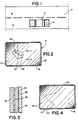
- a motor vehicle 12 is illustrated schematically travelling along a highway 14 of the two lane type, having a right or driving lane 16 and an opposite or passing lane 18.
- the driver of the vehicle 12 wish to pass a forwardly positioned vehicle (not illustrated)
- the driver could then pull his vehicle into the passing lane or left lane 18 to quickly and efficiently pass the slower moving vehicle in front.
- the vehicle 12 is equipped with a vehicle safety mirror which is affixed to the automobile as a side mount mirror 10 on the driver's side.
- the side mount mirror 10 is conventionally rectangular (or other shape) in configuration and includes a metallic frame 20 of suitable construction to securely affix to the vehicle 12 in well known manner.
- the side mount mirror of the present invention is fabricated of safety glass and includes a laminated or sandwich-like construction comprising a front or top glass panel 22, a rear or bottom glass panel 24 and a plastic layer 26 laminated therebetween.
- a silver or other suitable mirror surface 28 is applied rearwardly to the bottom glass panel 24 in known mannerto provide a reflecting construction.
- the laminated plastic layer 26 is subdivided into a yellow plastic layer 36 and a red plastic layer 38.
- a safety demarcation line 30 is defined between the yellow layer 36 and the red layer 38. Accordingly, when an overtaking vehicle is seen by the driver to be to the right of the demarcation line 30, the image of the oncoming vehicle will be viewed in the yellow or "pass with caution" zone 32. Similarly, when the trailing vehicle is so close as to have a portion of its image viewed by the driver (not shown) in the red or non-safe zone, the driver can then quickly ascertain that it is not safe for him to enter the left lane 18 for passing purposes.
- demarcation line 30 has been illustrated as a straight line, it will be appreciated that an oncoming vehicle is not entirely regular in configuration and portions of such a vehicle may extend over a straight demarcation line 30 even though the trailing vehicle is at a safe distance behind. Accordingly, the demarcation line 40 (and the underlying laminated plastic layer) may be configured to other than a straight line separation to accommodate such vehicle irregularities as the roof, wheels, hood, etc.
- shaped or curved demarcation line 40 of Fig. 4 may be more accurate than the straight demarcation line of Fig. 2, it will be appreciated that the viewing and consequently the speed of determination of caution and non-safe conditions can be more readily made in the configuration of Fig 2 rather than the configuration of Fig 4. Accordingly, many drivers may prefer to lose a little in the way of accuracy in orderto make up this loss by the speed and ease of determination.
- the driver In using the mirror 10 of Fig. 2, the driver (not shown) simply looks through the side view mirror 10 to determine the position of the image of overtaking traffic. If an overtaking vehicle appears in the caution zone 32 entirely to the right of the demarcation line 30, he knows that is nominally safe for him to enter the passing lane. In the event any part of the image of the overtaking vehicle appears to the driver on the red of non-safe zone 34 to the left of the demarcation line 30, then the driver will know that it is not safe to enter the passing lane 18 because the oncoming vehicle is less than two or two and one-half lengths behind and therefore too close for safety purposes.
- the driver will view the image of oncoming traffic in the mirror and determine the position of an overtaking vehicle. If the entire portion of the overtaking vehicle appears within the caution zone 42, that is the yellow zone, then the driver knows at a glance that is at least nominally safe for him to enter the passing lane 18 for passing a vehicle in front of him. However, if a major portion of an overtaking vehicle appears in the red or non-safe passing zone 44, he will then know not to enter the lane 18 and this determination can be made very quickly and accurately. If the major portion of the overtaking vehicle appears in the caution zone 42 and only the roof or wheels appear in the non-safe zone 44, then the driver will be able to determine with somewhat greater accuracy that is clear for him to pass the vehicle in front of him with adequate safety.
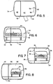
- a modified safety mirror 46 that is fabricated similar to the safety mirror of Fig. 2 and includes generally a red or "unsafe” indicating area 48, a yellow or “caution” indicating area 50, and a line of demarcation 52 therebetween.
- a frame 54 is provided in usual manner to mount the colored indicating areas 48, 50 and to affix the device 46 to a fixed portion of the automobile or other vehicle 12.
- an L-shaped guide 56 is formed in the caution area 50.
- the guide 56 is spaced from the line of demarcation and preferably is positioned near the lower right corner of the frame 54 in a location nearest to the vehicle 12 to which the safety mirror 46 is attached.
- the guide 56 comprises a vertical guide line 58 and a horizontal guide line 60, the horizontal guide line intersecting the vertical guide at its upper terminus at right angles.
- the frame 54 is moved until the vertical plane defining the left extent of the left rear quarter panel 62 aligns with the vertical guide line 58 and the top of the left rear quarter panel aligns with the horizontal guide line 60.
- the safety mirror 46 can be quickly adjusted as to lateral and vertical angularity to facilitate similar rearward viewing by any driver, regardless of his size.
- the demarcation line 52 and the sight guide 56 define a safety area or "sight" 62 therebetween whereby, when the driver observes a trailing automobile 64 in the "sight" area 62, he can immediately determine that it is apparently safe to change lanes for passing, depending of course upon other road conditions.
- the image of a trailing automobile 64 indicates clearly an unsafe lane changing situation.
- the image of the trailing automobile 64 appears as in Fig. 7, in view of the proximity of the image to the demarcation line 52, with all of the image displayed in the caution area 50, the driver will know that a marginally safe lane changing condition exists.
- the arrangement of Fig. 8 indicates clearly that a safe lane changing condition exists.
Landscapes
- Engineering & Computer Science (AREA)
- Physics & Mathematics (AREA)
- Multimedia (AREA)
- Mechanical Engineering (AREA)
- General Physics & Mathematics (AREA)
- Optics & Photonics (AREA)
- Rear-View Mirror Devices That Are Mounted On The Exterior Of The Vehicle (AREA)
- Optical Elements Other Than Lenses (AREA)
Abstract
Claims (6)
Priority Applications (1)
| Application Number | Priority Date | Filing Date | Title |
|---|---|---|---|
| AT84901044T ATE33905T1 (de) | 1983-02-22 | 1984-02-09 | Sicherheitsaussenspiegel. |
Applications Claiming Priority (2)
| Application Number | Priority Date | Filing Date | Title |
|---|---|---|---|
| US06/468,132 US4482210A (en) | 1982-09-30 | 1983-02-22 | Safety mirror |
| US468132 | 1983-02-22 |
Publications (3)
| Publication Number | Publication Date |
|---|---|
| EP0136330A1 EP0136330A1 (fr) | 1985-04-10 |
| EP0136330A4 EP0136330A4 (fr) | 1985-04-23 |
| EP0136330B1 true EP0136330B1 (fr) | 1988-04-27 |
Family
ID=23858555
Family Applications (1)
| Application Number | Title | Priority Date | Filing Date |
|---|---|---|---|
| EP84901044A Expired EP0136330B1 (fr) | 1983-02-22 | 1984-02-09 | Retroviseur externe de securite |
Country Status (5)
| Country | Link |
|---|---|
| US (1) | US4482210A (fr) |
| EP (1) | EP0136330B1 (fr) |
| JP (1) | JPS60500710A (fr) |
| DE (1) | DE3470807D1 (fr) |
| WO (1) | WO1984003361A1 (fr) |
Families Citing this family (13)
| Publication number | Priority date | Publication date | Assignee | Title |
|---|---|---|---|---|
| US5037303A (en) * | 1989-09-22 | 1991-08-06 | Irwin Jack L | Ski training mirror method and apparatus |
| DE4004732A1 (de) * | 1990-02-15 | 1991-08-22 | Bayerische Motoren Werke Ag | Nichtblendender rueckblickspiegel, insbesondere fuer kraftfahrzeuge |
| US5644442A (en) * | 1994-06-28 | 1997-07-01 | Lemere; Peter N. | Spherical rear view mirror target marking system and method |
| US5805367A (en) * | 1995-01-17 | 1998-09-08 | Murakami Kaimeido Co., Ltd. | Multifunctional rearview mirror system |
| US5844721A (en) * | 1996-02-09 | 1998-12-01 | Karpen; Daniel Nathan | Motor vehicle rearview mirror |
| USD431219S (en) * | 1999-02-03 | 2000-09-26 | Rosco Inc. | Vehicular mirror |
| US6461158B1 (en) * | 2000-08-14 | 2002-10-08 | The Procter & Gamble Company | Products and methods that simulate changes in tooth color |
| US6932484B2 (en) * | 2003-09-26 | 2005-08-23 | Dale E. Brandt | Rear view mirror assembly |
| US20070041107A1 (en) * | 2005-08-19 | 2007-02-22 | Lyon Richards P | Vehicle mirror with improved reflected object distance gauging indication and method |
| US20100103545A1 (en) * | 2008-10-28 | 2010-04-29 | Ford Global Technologies, Llc | Rear view mirror |
| DE102009009379B3 (de) * | 2009-02-18 | 2010-07-01 | Mekra Lang Gmbh & Co. Kg | Spiegelanordnung für Fahrzeuge sowie Fahrzeug mit einer solchen Spiegelanordnung |
| US9102278B2 (en) * | 2013-02-20 | 2015-08-11 | Thomas M. Dauphinee | Left and right side view mirrors |
| US10384613B2 (en) * | 2017-12-12 | 2019-08-20 | Hamid Ayub | Enhanced vehicle side view mirror assembly |
Family Cites Families (10)
| Publication number | Priority date | Publication date | Assignee | Title |
|---|---|---|---|---|
| US1311253A (en) * | 1919-07-29 | stkeot | ||
| US1879592A (en) * | 1930-09-16 | 1932-09-27 | Guyer D Thomas | Distance-indicator for vehicles |
| US2514989A (en) * | 1947-09-09 | 1950-07-11 | Newton J Buren | Outside rear-vision mirror having contrasting colors |
| US2881655A (en) * | 1954-05-31 | 1959-04-14 | Eisenschink Anton | Rear view mirrors |
| US2871754A (en) * | 1954-06-11 | 1959-02-03 | Kingsley W Marble | Rearview mirror attachment |
| US3521234A (en) * | 1969-01-13 | 1970-07-21 | John Joseph Davin | Motor vehicle mirror tailgating observation and warning system |
| US3772795A (en) * | 1971-05-28 | 1973-11-20 | A Calvet | Range, trailing distance and safe passing indicator for motor vehicle operators |
| US3859732A (en) * | 1972-02-29 | 1975-01-14 | John Joseph Davin | Preceding motor vehicle observation spacing guide |
| DE2960226D1 (en) * | 1978-05-19 | 1981-04-23 | Luchtenberg Gmbh & Co | Angle mirror |
| US4311362A (en) * | 1980-05-02 | 1982-01-19 | Laporte Thomas A | Two-position aerodynamic mirror |
-
1983
- 1983-02-22 US US06/468,132 patent/US4482210A/en not_active Expired - Fee Related
-
1984
- 1984-02-09 WO PCT/US1984/000182 patent/WO1984003361A1/fr not_active Ceased
- 1984-02-09 JP JP59501018A patent/JPS60500710A/ja active Pending
- 1984-02-09 EP EP84901044A patent/EP0136330B1/fr not_active Expired
- 1984-02-09 DE DE8484901044T patent/DE3470807D1/de not_active Expired
Also Published As
| Publication number | Publication date |
|---|---|
| EP0136330A1 (fr) | 1985-04-10 |
| EP0136330A4 (fr) | 1985-04-23 |
| JPS60500710A (ja) | 1985-05-16 |
| DE3470807D1 (en) | 1988-06-01 |
| US4482210A (en) | 1984-11-13 |
| WO1984003361A1 (fr) | 1984-08-30 |
Similar Documents
| Publication | Publication Date | Title |
|---|---|---|
| EP0136330B1 (fr) | Retroviseur externe de securite | |
| CN108109413B (zh) | 一种无人驾驶车辆与非智能交通参与者的信息交互系统 | |
| US5289321A (en) | Consolidated rear view camera and display system for motor vehicle | |
| EP3236447B1 (fr) | Système et procédé de projection d'informations de véhicule | |
| JP5694243B2 (ja) | 自動車用撮像システムを備える障害物検出装置 | |
| US4941263A (en) | System for aiding a driver's depth perception | |
| US5923243A (en) | Motor vehicle collision avoidance signalling device | |
| US5424875A (en) | Motor vehicle safety mirror | |
| US20190031102A1 (en) | Image display system for vehicle use and vehicle equipped with the image display system | |
| US20180236939A1 (en) | Method, System, and Device for a Forward Vehicular Vision System | |
| JPH06255399A (ja) | 車両の表示装置 | |
| US7650698B2 (en) | Visual driving aid | |
| US2622482A (en) | Traffic viewing device | |
| CN208180895U (zh) | 带前置摄像头的汽车外后视镜 | |
| US9994146B2 (en) | Blind spot indicator | |
| EP0235993A1 (fr) | Miroirs pour véhicules | |
| JPH06255397A (ja) | 車両の表示装置 | |
| JPH04219900A (ja) | 車間距離確認装置 | |
| JP2577566Y2 (ja) | 車両確認用反射鏡 | |
| KR200239140Y1 (ko) | 자동차의 사이드미러 | |
| CN214420333U (zh) | 一种安全辨距的汽车后视镜 | |
| US3947096A (en) | Rear-view mirror system for road vehicles | |
| JP2023138212A (ja) | 運転支援画像 | |
| CN2592441Y (zh) | 大型机动车用非穿透式潜望镜 | |
| WO2002062621A1 (fr) | Ensemble retroviseur pour vehicules |
Legal Events
| Date | Code | Title | Description |
|---|---|---|---|
| PUAI | Public reference made under article 153(3) epc to a published international application that has entered the european phase |
Free format text: ORIGINAL CODE: 0009012 |
|
| 17P | Request for examination filed |
Effective date: 19841022 |
|
| AK | Designated contracting states |
Designated state(s): AT BE CH DE FR GB LI LU NL SE |
|
| 17Q | First examination report despatched |
Effective date: 19861015 |
|
| GRAA | (expected) grant |
Free format text: ORIGINAL CODE: 0009210 |
|
| AK | Designated contracting states |
Kind code of ref document: B1 Designated state(s): AT BE CH DE FR GB LI LU NL SE |
|
| PG25 | Lapsed in a contracting state [announced via postgrant information from national office to epo] |
Ref country code: NL Effective date: 19880427 Ref country code: LI Effective date: 19880427 Ref country code: FR Free format text: THE PATENT HAS BEEN ANNULLED BY A DECISION OF A NATIONAL AUTHORITY Effective date: 19880427 Ref country code: CH Effective date: 19880427 Ref country code: BE Effective date: 19880427 Ref country code: AT Effective date: 19880427 |
|
| REF | Corresponds to: |
Ref document number: 33905 Country of ref document: AT Date of ref document: 19880515 Kind code of ref document: T |
|
| PG25 | Lapsed in a contracting state [announced via postgrant information from national office to epo] |
Ref country code: SE Effective date: 19880430 |
|
| REF | Corresponds to: |
Ref document number: 3470807 Country of ref document: DE Date of ref document: 19880601 |
|
| REG | Reference to a national code |
Ref country code: CH Ref legal event code: PL |
|
| NLV1 | Nl: lapsed or annulled due to failure to fulfill the requirements of art. 29p and 29m of the patents act | ||
| EN | Fr: translation not filed | ||
| PLBE | No opposition filed within time limit |
Free format text: ORIGINAL CODE: 0009261 |
|
| STAA | Information on the status of an ep patent application or granted ep patent |
Free format text: STATUS: NO OPPOSITION FILED WITHIN TIME LIMIT |
|
| PG25 | Lapsed in a contracting state [announced via postgrant information from national office to epo] |
Ref country code: LU Free format text: LAPSE BECAUSE OF NON-PAYMENT OF DUE FEES Effective date: 19890228 |
|
| 26N | No opposition filed | ||
| PGFP | Annual fee paid to national office [announced via postgrant information from national office to epo] |
Ref country code: GB Payment date: 19910211 Year of fee payment: 8 |
|
| PGFP | Annual fee paid to national office [announced via postgrant information from national office to epo] |
Ref country code: DE Payment date: 19910326 Year of fee payment: 8 |
|
| PG25 | Lapsed in a contracting state [announced via postgrant information from national office to epo] |
Ref country code: GB Effective date: 19920209 |
|
| GBPC | Gb: european patent ceased through non-payment of renewal fee | ||
| PG25 | Lapsed in a contracting state [announced via postgrant information from national office to epo] |
Ref country code: DE Effective date: 19921103 |