EP0135452B1 - Lifting device with at least one telescopic mast - Google Patents
Lifting device with at least one telescopic mast Download PDFInfo
- Publication number
- EP0135452B1 EP0135452B1 EP84420123A EP84420123A EP0135452B1 EP 0135452 B1 EP0135452 B1 EP 0135452B1 EP 84420123 A EP84420123 A EP 84420123A EP 84420123 A EP84420123 A EP 84420123A EP 0135452 B1 EP0135452 B1 EP 0135452B1
- Authority
- EP
- European Patent Office
- Prior art keywords
- pillar
- platform
- chassis
- distinguishing feature
- elevator according
- Prior art date
- Legal status (The legal status is an assumption and is not a legal conclusion. Google has not performed a legal analysis and makes no representation as to the accuracy of the status listed.)
- Expired
Links
Images


Classifications
-
- B—PERFORMING OPERATIONS; TRANSPORTING
- B66—HOISTING; LIFTING; HAULING
- B66F—HOISTING, LIFTING, HAULING OR PUSHING, NOT OTHERWISE PROVIDED FOR, e.g. DEVICES WHICH APPLY A LIFTING OR PUSHING FORCE DIRECTLY TO THE SURFACE OF A LOAD
- B66F11/00—Lifting devices specially adapted for particular uses not otherwise provided for
- B66F11/04—Lifting devices specially adapted for particular uses not otherwise provided for for movable platforms or cabins, e.g. on vehicles, permitting workmen to place themselves in any desired position for carrying out required operations
Abstract
Description
La présente invention concerne un élévateur comportant au moins un mât télescopique.The present invention relates to an elevator comprising at least one telescopic mast.
Il existe à ce jour plusieurs types d'élévateurs comportant une plate-forme ou une nacelle permettant de faire travailler un ou des opérateurs à une certaine hauteur par rapport au sol, par exemple pour l'entretien ou la réfection de façades de bâtiments, de lampadaires de grande hauteur, l'entretien de charpentes de hangars, etc...To date, there are several types of elevators comprising a platform or a nacelle making it possible to have one or more operators work at a certain height above the ground, for example for the maintenance or repair of building facades, high-rise lampposts, maintenance of hangars, etc.
Un premier type d'élévateur concerne les élévateurs hydrauliques comportant une nacelle pouvant accepter une ou deux personnes. L'élévation est obtenue par le mouvement de bras mécano-soudés articulés entre eux et commandés généralement par des vérins hydrauliques. Outre le fait qu'ils sont très coûteux, ces appareils sont encombrants lorsqu'ils sont repliés au sol.A first type of elevator concerns hydraulic elevators comprising a gondola that can accept one or two people. The elevation is obtained by the movement of mechanically welded arms hinged together and generally controlled by hydraulic cylinders. Besides the fact that they are very expensive, these devices are bulky when folded to the ground.
Un autre type d'élévateur comprend une plate- forme de travail animée d'un mouvement d'élévation verticale obtenue par l'action d'un ou de plusieurs vérins hydrauliques agissant sur un dispositif de bras articulés entre eux suivant la technique dite "du ciseau". Ces appareils sont lourds et coûteux, et présentent, d'un point de vue fonctionnel, l'inconvénient d'une limitation importante en hauteur.Another type of elevator comprises a working platform animated by a vertical elevation movement obtained by the action of one or more hydraulic cylinders acting on a device of arms articulated together according to the technique known as "of chisel". These devices are heavy and expensive, and have, from a functional point of view, the disadvantage of a significant limitation in height.
Un troisième type d'elevateur comprend une nacelle ou plateforme de travail fixée a l'extrémite d'un mât central télescopique, le mouvement d'élévation verticale étant obtenu par déploiement de ce mât à l'aide de moyens hydrauliques ou mécaniques.A third type of elevator comprises a nacelle or working platform fixed to the end of a telescopic central mast, the vertical elevation movement being obtained by deployment of this mast using hydraulic or mechanical means.
Outre le fait qu'ils sont très coûteux, ces appareils sont encombrants et très lourds.Besides the fact that they are very expensive, these devices are bulky and very heavy.
Il existe également des élévateurs à un seul mât télescopique dans lesquels le mât replie occupe une position verticale très encombrante au-dessus du châssis.There are also elevators with a single telescopic mast in which the folded mast occupies a very bulky vertical position above the chassis.
Il existe enfin des élévateurs comportant deux mâts télescopiques disposés à deux extrémités de la plate-forme de travail, le mouvement vertical de la plate-forme étant obtenu par déploiement ou télescopage simultane des deux mâts à partir d'un seul treuil manuel ou électrique.Finally, there are elevators comprising two telescopic masts disposed at two ends of the working platform, the vertical movement of the platform being obtained by simultaneous deployment or telescoping of the two masts from a single manual or electric winch.
Néanmoins, la mise en oeuvre de l'elevateur avant l'operation de telescopage est longue et délicate.However, the implementation of the elevator before the telescoping operation is long and delicate.
Elle consiste à faire pivoter manuellement de la position horizontale ou proche de l'horizontale a la position verticale les deux mâts. Après avoir été verrouillés manuellement dans cette position, les deux mats verticaux sont équipés de la plate- forme de travail. Ceci constitue une opération longue et pouvant présenter certains risques pour l'opérateur.It consists in manually pivoting from the horizontal position or close to the horizontal to the vertical position the two masts. After having been manually locked in this position, the two vertical masts are equipped with the working platform. This constitutes a long operation and may present certain risks for the operator.
En position repliée, les deux mâts horizontaux sont superposés, ce qui constitue une solution encombrante, et necessite une construction dissymétrique du châssis principalement au niveau de l'articulation des mâts.In the folded position, the two horizontal masts are superimposed, which constitutes a bulky solution, and requires an asymmetrical construction of the chassis mainly at the articulation of the masts.
La présente invention vise à remédier a ces inconvenients.The present invention aims to remedy these drawbacks.
A cet effet, dans l'élévateur qu'elle concerne du type comprenant au moins un mât télescopique articulé sur un châssis sensiblement horizontal à proximité de l'une de ses extrémités autour d'un axe horizontal (FR-E 2 294 980), l'axe d'articulation du mât sur le châssis est situé dans un plan horizontal au-dessus du plan supérieur du châssis, afin de permettre le logement de la plate- forme entre le châssis et le mât, lorsque celui-ci est replié à l'horizontale, la plate-forme demeurant associée à chaque mât lorsque celui-ci est à l'horizontale.To this end, in the elevator that it relates to of the type comprising at least one telescopic mast articulated on a substantially horizontal frame near one of its ends around a horizontal axis (FR-
Cet élévateur présente l'avantage d'être d'un encombrement réduit et de constituer un appareil complet ne nécessitant pas le rajout de pièces supplémentaires pour le passage de la position pliée à la position dépliée. En outre, le fait qu'en position pliée les mâts se trouvent au-dessus du châssis permet, outre le logement de la plate- forme, le logement d'autres organes tels que le moteur d'actionnement des mâts et de la plate- forme.This elevator has the advantage of being reduced in size and of constituting a complete device not requiring the addition of additional parts for the passage from the folded position to the unfolded position. In addition, the fact that in the folded position the masts are above the chassis allows, in addition to the housing of the platform, the housing of other members such as the motor for actuating the masts and the platform. form.
Cet élévateur est équipé de moyens permettant, dans un premier temps, le pivotement de chaque mât depuis sa position horizontale jusqu'en position verticale, puis le déploiement des mâts et le deplacement de la plate-forme le long de ceux-ci.This elevator is equipped with means allowing, at first, the pivoting of each mast from its horizontal position to the vertical position, then the deployment of the masts and the displacement of the platform along them.
L'automatisation des moyens d'actionnement des mâts et de la plate-forme permet a un seul operateur la mise en place et le déploiement de l'élévateur sur le lieu de travail sans autres opérations que la commande de la motorisation des mâts et de la plate-forme.The automation of the means of actuation of the masts and of the platform allows a single operator to set up and deploy the elevator at the workplace without other operations than controlling the motorization of the masts and the platform.
Dans la mesure où cet élevateur comporte plusieurs mâts, associés a deux extremités opposées de la plate-forme, les différents mâts sont décalés les uns par rapport aux autres de manière à pivoter dans des plans parallèles suffisamment éloignés les uns des autres, pour que les différents mâts puissent être juxtaposés dans un même plan horizontal en position repliée.Insofar as this breeder comprises several masts, associated with two opposite ends of the platform, the different masts are offset with respect to each other so as to pivot in parallel planes sufficiently distant from each other, so that the different masts can be juxtaposed in the same horizontal plane in the folded position.
Cette solution est très intéressante car assurant une grande compacité de l'appareil en position pliée, tout en simplifiant sa réalisation par standardisation des pièces utilisées pour les differents mâts, puisque ceux-ci sont articulés à la même distance du châssis.This solution is very interesting because it ensures a high compactness of the device in the folded position, while simplifying its production by standardizing the parts used for the different masts, since these are articulated at the same distance from the chassis.
Conformément à une autre forme d'exécution de cet élévateur, chaque mât est constitué par plusieurs profiles tubulaires télescopiques emboités les uns dans les autres, dont celui de plus grande section comprend, sur sa face tournée vers le milieu de l'appareil, deux profilés longitudinaux formant rails de guidage pour un chariot de la plate-forme et dont celui de plus petite section, de longueur supérieure à celle des autres profilés, est équipé, dans sa partie débordant de ceux-ci en position emboitée des différents profilés, de deux rails disposés dans le prolongement des précédents, les moyens d'entraînement de la plate-forme et de coulissement des éléments de chaque mât étant tels que, partant de la position basse de la plate- forme, celle-ci soit déplacée vers le haut jusqu'à ce que chaque chariot soit engagé dans les rails des profilés de plus petite section, avant le debut du coulissement vers l'extérieur des différents profilés constitutifs des mâts.In accordance with another embodiment of this elevator, each mast is constituted by several telescopic tubular profiles fitted into one another, of which that of larger section comprises, on its face facing the middle of the apparatus, two profiles longitudinal forming guide rails for a carriage of the platform and of which that of smaller section, of length greater than that of the other profiles, is equipped, in its projecting portion thereof in the nested position of the different profiles, of two rails arranged in the extension of the previous ones, the means for driving the platform and for sliding the elements of each mast being such that, starting from the low position of the platform form, it is moved upwards until each carriage is engaged in the rails of the sections of smaller section, before the start of the sliding towards the outside of the different sections constituting the masts.
Cette solution est intéressante, d'un point de vue de la réalisation, car permettant d'utiliser des éléments simples tels que des profilés tubulaires, tout en permettant de réaliser des mâts possédant une excellente rigidité. En outre, d'un point de vue pratique, il est avantageux que la plate-forme se trouve toujours en position haute des mâts car permettant à l'operateur de se trouver le plus près possible de la zone où une intervention doit être effectuée.This solution is interesting, from an implementation point of view, since it allows the use of simple elements such as tubular sections, while making it possible to produce masts having excellent rigidity. In addition, from a practical point of view, it is advantageous that the platform is always in the high position of the masts because allowing the operator to be as close as possible to the area where an intervention must be carried out.
De toute façon, l'invention sera bien comprise à l'aide de la description qui suit en reférence au dessin schématique annexé representant, à titre d'exemples non limitatifs, plusieurs formes d'execution de cet élévateur:.
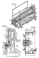
- Figure 1 est une vue en perspective d'un premier élevateur à deux mâts, les mâts étant déployés et la plate-forme étant en position haute;
- Figure 2 en est une vue en perspective, les mâts étant basculés en position verticale et la plate-forme étant en position basse;
- Figure 3 en est une vue en perspective, les mâts étant en position repliée;
- Figure 4 est une vue en perspective d'une extrémité de la plate-forme et du chariot sur lequel elle est montée,;
- Figure 5 est une vue en coupe verticale et à échelle agrandie selon la ligne 5-5 de figure 2 de la partie inférieure d'un mât,;
- Figure 6 est une vue en coupe horizontale de la partie inférieure d'un mât selon la ligne 6-6 de figure 5;
- Figure 7 est une vue similaire à celle de figure 5 en position déverrouillée du mât,;
- Figure 8 est une vue de la partie inférieure d'un mât en position horizontale;
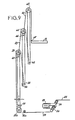
- Figure 9 est une vue très schématique du système d'entraînement des différents éléments de mâts;
- Figure 10 est une vue en coupe transversale passant par les extrémités superieures des différents élements d'un mât;
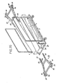
- Figure 11 est une vue en perspective d'une variante d'exécution d'un mât réalisé à partir de profilés tubulaires;
- Figure 12 est une vue très schématique du système d'entraînement des éléments du mât de figure 11;
- Figure 13 est une vue en perspective d'un premier chariot destiné à être guidé dans le mât de figure 11;
- Figures 14 et 15 sont deux vues partielles en coupe longitudinale. d'un mât equipé du chariot de figure 13, respectivement en position verticale et en position horizontale;
- Figures 16 et 17 sont deux vues partielles en coupe longitudinale d'un mât équipé d'un chariot constituant une variante d'exécution de celui de figure 13, respectivement en position verticale et en position horizontale;
- Figures 18 et 19 sont deux vues partielles, en coupe longitudinale, d'un mât equipe d'un chariot constituant une autre variante de celui de figure 13, respectivement en position verticale et en position horizontale;
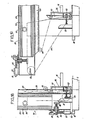
- Figure 20 est une vue schématique en perspective d'un élévateur a deux mâts équipés d'une embase de surélévation du châssis;
- Figure 21 est une vue de côte de l'élévateur de figure 20 au cours du mouvement de pivotement des mâts de la position horizontale à la position verticale;
- Figure 22 est une vue de cêté de l'élévateur de figure 20, les mâts étant en position verticale;
- Figure 23 est une vue de côte de l'élévateur de figure 20, le châssis reposant sur l'embase de surélévation, et les mâts étant repliés en position horizontale, ;
- Figure 24 est une vue de côté d'un élévateur a un mât, celui-ci étant en position verticale;
- Figure 25 est une vue en coupe transversale de cet élévateur suivant la ligne 25-25 de figure 24;
- Figure 26 est une vue de cêté de cet élévateur, le mât étant déployé;
- Figure 27 est une vue de cêté de cet élévateur, le mât etant replié en position horizontale;
- Figure 28 est une vue en perspective et à échelle agrandie des moyens de verrouillage du mât.
- Figure 1 is a perspective view of a first two-mast elevator, the masts being deployed and the platform being in the high position;
- Figure 2 is a perspective view, the masts being tilted in the vertical position and the platform being in the low position;
- Figure 3 is a perspective view, the masts being in the folded position;
- Figure 4 is a perspective view of one end of the platform and the carriage on which it is mounted;
- Figure 5 is a vertical sectional view on an enlarged scale along line 5-5 of Figure 2 of the lower part of a mast;
- Figure 6 is a horizontal sectional view of the lower part of a mast along line 6-6 of Figure 5;
- Figure 7 is a view similar to that of Figure 5 in the unlocked position of the mast;
- Figure 8 is a view of the lower part of a mast in a horizontal position;
- Figure 9 is a very schematic view of the drive system of the different mast elements;
- Figure 10 is a cross-sectional view passing through the upper ends of the different elements of a mast;
- Figure 11 is a perspective view of an alternative embodiment of a mast made from tubular profiles;
- Figure 12 is a very schematic view of the drive system of the elements of the mast of Figure 11;
- Figure 13 is a perspective view of a first carriage intended to be guided in the mast of Figure 11;
- Figures 14 and 15 are two partial views in longitudinal section. a mast fitted with the carriage of Figure 13, respectively in vertical position and in horizontal position;
- Figures 16 and 17 are two partial views in longitudinal section of a mast equipped with a carriage constituting an alternative embodiment of that of Figure 13, respectively in vertical position and in horizontal position;
- Figures 18 and 19 are two partial views, in longitudinal section, of a mast fitted with a carriage constituting another variant of that of Figure 13, respectively in vertical position and in horizontal position;
- Figure 20 is a schematic perspective view of a two-mast elevator equipped with a base for raising the chassis;
- Figure 21 is a side view of the elevator of Figure 20 during the pivoting movement of the masts from the horizontal position to the vertical position;
- Figure 22 is a side view of the elevator of Figure 20, the masts being in vertical position;
- Figure 23 is a side view of the elevator of Figure 20, the frame resting on the raised base, and the masts being folded in a horizontal position;
- Figure 24 is a side view of a lift with a mast, the latter being in a vertical position;
- Figure 25 is a cross-sectional view of this elevator along line 25-25 of Figure 24;
- Figure 26 is a side view of this elevator, the mast being deployed;
- Figure 27 is a side view of this elevator, the mast being folded in a horizontal position;
- Figure 28 is a perspective view on an enlarged scale of the mast locking means.
L'élévateur, représenté aux figures 1 à 10, comprend un châssis horizontal (2) formé par un cadre monté sur des roulettes (3). Cependant, il faut noter que ce châssis pourrait être disposé sur le plateau d'un véhicule, sur une remorque, ou être automoteur en fonction de l'utilisation recherchée.The elevator, shown in Figures 1 to 10, comprises a horizontal frame (2) formed by a frame mounted on casters (3). However, it should be noted that this chassis could be placed on the platform of a vehicle, on a trailer, or be self-propelled depending on the desired use.
Ce châssis porte, à chacune de ses extremites, deux séries de supports (4) décalées latéralement l'une par rapport a l'autre, chaque série de supports (4) portant, a son extrémité supérieure, un axe (5) servant à l'articulation d'un mât (6). Les axes d'articulation (5) des mâts (6) sont parallèles et disposés dans un plan horizontal situé au-dessus du châssis (2).This chassis carries, at each of its ends, two series of supports (4) offset laterally with respect to each other, each series of supports (4) carrying, at its upper end, an axis (5) serving to the articulation of a mast (6). The axes of articulation (5) of the masts (6) are parallel and arranged in a horizontal plane situated above the chassis (2).
L'axe d'articulation (5) de chaque mât est disposé de telle sorte que quand celui-ci est en position verticale, la ligne verticale passant par son centre de gravité est située entre l'axe d'articulation et le centre de l'appareil, facilitant ainsi le basculement des mâts vers la position horizontale.The axis of articulation (5) of each mast is arranged so that when it is in the vertical position, the vertical line passing through its center of gravity is located between the axis of articulation and the center of the 'apparatus, thus facilitating the tilting of the masts towards the horizontal position.
Chaque mât (6) comprend trois parties télescopiques dont chacune est constituée par deux éléments entretoises. Chaque élément (7) possède une forme de double U dont une gorge (8) sert au logement et à la fixation d'entretoises (9) assurant sa liaison avec l'autre élément (7), et une gorge (10) servant au guidage d'un élément (7) de section immédiatement inférieure, ou de galets (12) pour l'élement de plus petite section.Each mast (6) comprises three telescopic parts, each of which consists of two spacer elements. Each element (7) has a double U shape, a groove (8) for housing and fixing spacers (9) ensuring its connection with the other element (7), and a groove (10) for guiding an element (7) of immediately lower section, or rollers (12) for the element of smaller section.
Les galets (12) appartiennent à un chariot (13) associé à chaque mât. A cet effet, ce chariot comprend quatre galets entretoisés. L'une des entretoises du chariot (13) comporte deux chapes verticales et parallèles (14) servant à l'articulation autour d'un axe parallèle aux axes d'articulation (5) des mâts, d'un cadre (15) portant la plate- forme (16). Comme montré au dessin, celie-ci est équipée, de façon connue, d'un garde-corps (17), dans les zones qui ne sont pas situées en regard des mâts.The rollers (12) belong to a carriage (13) associated with each mast. For this purpose, this carriage includes four braced rollers. One of the carriage spacers (13) has two vertical and parallel yokes (14) used for articulation about an axis parallel to the articulation axes (5) masts, a frame (15) carrying the platform (16). As shown in the drawing, this is fitted, in a known manner, with a railing (17), in the areas which are not located opposite the masts.
Ce mode de montage de la plate-forme et d'articulation des mâts permet, lors du repliage à l'horizontale de ceux-ci, de loger la plate-forme (16) sous eux, comme montré à la figure 3, ce qui conduit à une réalisation très compacte.This mounting method of the platform and articulation of the masts makes it possible, when folding them horizontally, to accommodate the platform (16) under them, as shown in FIG. 3, which leads to a very compact design.
Comme montré au dessin, chaque mât (6) est équipé d'un système assurant son verrouillage en position verticale. Ce système comprend deux douiiles (18) solidaires du châssis (2) formant des gâches dans lesquelles pénètrent deux pênes constitués par deux tiges (19) montées coulissantes longitudinalement au mât dans des manchons (20) et soumises chacune à l'action d'un ressort (22) tendant a faire dépasser la tige (19) de l'extrémite inférieure du mât. Lors du passage du mât de la position horizontale à ia position verticale, chaque pêne (19) pénètre dans une gâche (18) en fin de mouvement de pivotement. Ce verrouillage ne peut être liberé que manuellement, par exemple à l'aide d'une butée (23) maintenant les pênes en position sortie, comme montré à la figure 7, imposant à l'opérateur de descendre de la plate-forme pour déverrouiller manuellement les deux mâts. Ceci évite que, par suite d'une fausse manoeuvre, l'operateur provoque le repliage des mâts, alors qu'il est encore sur la plate-forme.As shown in the drawing, each mast (6) is equipped with a system ensuring its locking in the vertical position. This system comprises two douiiles (18) integral with the chassis (2) forming strikes into which penetrate two bolts constituted by two rods (19) slidably mounted longitudinally to the mast in sleeves (20) and each subjected to the action of a spring (22) tending to cause the rod (19) to protrude from the lower end of the mast. During the passage of the mast from the horizontal position to the vertical position, each bolt (19) enters a keeper (18) at the end of the pivoting movement. This locking can only be released manually, for example using a stop (23) holding the bolts in the extended position, as shown in FIG. 7, requiring the operator to descend from the platform to unlock manually the two masts. This avoids that, as a result of a false maneuver, the operator causes the folding of the masts, while he is still on the platform.
Chaque mât est, en outre, équipé d'un système de verrouillage des différentes parties le constituant, lorsqu'elles sont en position rentrée les unes dans les autres. Ce système comprend une plaque (24) solidaire de la deuxième partie d'éléments télescopiques, comportant un orifice central (25) dans lequel est destinée a pénétrer une tige (26) solidaire de la partie extérieure du mât. Cette tige (26) est solidaire d'une plaque (27) reliée par deux colonnes (28), parallèles à la tige (26), à une autre plaque (29) située de l'autre côte de la plaque (24) par rapport à la tige (26).Each mast is also equipped with a locking system for the various parts constituting it, when they are in the retracted position one inside the other. This system comprises a plate (24) integral with the second part of telescopic elements, comprising a central orifice (25) into which is intended to penetrate a rod (26) integral with the external part of the mast. This rod (26) is integral with a plate (27) connected by two columns (28), parallel to the rod (26), to another plate (29) located on the other side of the plate (24) by relative to the rod (26).
Des ressorts (30) maintiennent normalement la tige (26) en position poussée vers la plaque de verrouillage (24). Une butée (32), associée a chaque mât, est montée sur le châssis (2), contre laquelle vient prendre appui la plaque (29), Jorsque le mât arrive en position verticale. L'action exercée sur la plaque (29), transmise par les colonnes (28), provoque le retrait de la tige (26) hors de l'orifice (25) de la plaque (24).Springs (30) normally hold the rod (26) in the pushed position toward the locking plate (24). A stop (32), associated with each mast, is mounted on the chassis (2), against which the plate (29) comes to bear. When the mast arrives in a vertical position. The action exerted on the plate (29), transmitted by the columns (28), causes the withdrawal of the rod (26) out of the orifice (25) of the plate (24).
Les différentes parties du mât peuvent alors coulisser librement. En période de pliage de l'élévateur, ce verrouillage se produit dès le début du pivotement de chaque mât, au moment où la plaque (29) échappe à la butée (32).The different parts of the mast can then slide freely. During the folding period of the elevator, this locking occurs from the start of the pivoting of each mast, when the plate (29) escapes the stop (32).
Une telle disposition est intéressante car permettant au système d'entraînement dont le fonctionnement est décrit ci-après, de n'agir que pour le pivotement du mât, tant que celui-ci n'est pas en position verticale.Such an arrangement is advantageous because allowing the drive system, the operation of which is described below, to act only for the pivoting of the mast, as long as the latter is not in the vertical position.
Les moyens d'entraînement de l'élévateur sont constitués par un moteur électrique (33) situé à la partie inférieure du châssis, comportant un arbre de sortie sur lequel sont calés deux tambours (34) sur lesquels sont enroulés deux câbles (35), selon des enroulements inverses, chaque câble étant associé à un mât.The elevator drive means are constituted by an electric motor (33) located at the lower part of the chassis, comprising an output shaft on which two drums (34) are wedged on which two cables (35) are wound, according to reverse windings, each cable being associated with a mast.
Chaque câble (35) passe tout d'abord sur une poulie (36a) solidaire du châssis. L'axe de cette poulie, de même que l'axe de toutes les autres poulies décrites ci-apres, est parallèle à l'axe de pivotement du mât considéré. Le câble (35) passe ensuite sur deux poulies (36b) et (37) montées respectivement aux extrémités inférieure et supérieure de la partie de plus grande section du mât. L'extrémité libre du câble (35) est fixée en (38) à l'extrémité inférieure de la deuxième partie du mât. Un second câble (39) passant sur une poulie (40) disposée à l'extrémité supérieure de la seconde partie du mât est fixée par ses extrémités, respectivement, en (42) à l'extrémité haute de la partie de plus grande section du mât et en (43) en partie basse de la troisième partie du mât. Enfin, un câble (44) passant sur une poulie (45) disppsée en partie haute du mât est fixe par ses extrémités, en (46) à l'extrémité supérieure de la seconde partie du mât et en (47) sur la plate- forme.Each cable (35) first passes over a pulley (36a) secured to the chassis. The axis of this pulley, like the axis of all the other pulleys described below, is parallel to the pivot axis of the mast in question. The cable (35) then passes over two pulleys (36b) and (37) mounted respectively at the lower and upper ends of the part of the largest section of the mast. The free end of the cable (35) is fixed at (38) to the lower end of the second part of the mast. A second cable (39) passing over a pulley (40) disposed at the upper end of the second part of the mast is fixed by its ends, respectively, at (42) at the high end of the part of larger section of the mast and in (43) in the lower part of the third part of the mast. Finally, a cable (44) passing over a pulley (45) in the upper part of the mast is fixed at its ends, at (46) at the upper end of the second part of the mast and at (47) on the platform. form.
D'un point de vue pratique, le fonctionnement de cet élévateur depuis sa position pliée représentée a la figure 3 est le suivant:From a practical point of view, the operation of this elevator from its folded position shown in FIG. 3 is as follows:
L'actionnement du moteur (33) provoquant un enroulement des câbles (35) sur les tambours (34) se traduit, comme montré à la figure 8, par un couple de basculement sur les deux mâts (6) provoquant le passage de ceux-ci de la position horizontale à la position verticale. Au cours de ce mouvement, les différentes parties des deux mâts ne peuvént pas se déployer, étant maintenues verrouillées les unes relativement aux autres, grâce au vérrou (26) - (30). Lorsque les mâts arrivent en position verticale, l'appui sur les butées (32) provoque le déverrouillage les differentes parties des mâts les unes relativement aux autres permettant ainsi leur déploiement. En outre, lorsque les mâts arrivent en position verticale, ils se bloquent dans celle-ci par engagement des pênes (19) dans les gâches (18).The actuation of the motor (33) causing a winding of the cables (35) on the drums (34) results, as shown in FIG. 8, by a tilting torque on the two masts (6) causing the passage of these- ci from the horizontal position to the vertical position. During this movement, the different parts of the two masts can not deploy, being kept locked relative to each other, thanks to the lock (26) - (30). When the masts arrive in a vertical position, pressing on the stops (32) causes the different parts of the masts to be unlocked relative to one another, thus enabling them to be deployed. In addition, when the masts arrive in a vertical position, they lock in the latter by engagement of the bolts (19) in the strikes (18).
L'opérateur peut alors prendre place sur la plate-forme et commander la poursuite de l'enroulément des câbles (35) sur les tambours (34). Cétte operation se traduit grâce au circuit de câbles décrit precédemment par le déploiemént des parties télescopiques des deux mâts et le déplacément vers le haut de la plate-forme dans les élements de la troisième partie télescopique pour arrivér jusqu'à la position représentée à la figure 1.The operator can then take place on the platform and control the continuation of the winding of the cables (35) on the drums (34). This operation is reflected by the cable circuit described above by the deployment of the telescopic parts of the two masts and the movement up the platform in the elements of the third telescopic part to reach the position shown in the figure 1.
Pour répliér l'élévateur, il suffit d'actionner le moteur électrique (33) en position inverse. Les différentes parties des deux mâts pénètrent alors les unes dans lés autres et la plate-forme s'abaisse jusqu'à venir dans la position représentée à la figure 2. L'opérateur doit alors quitter la plate-forme pour déverrouiller manuellement les pênes (19) et les maintenir en position déverrouillée à l'aide des butées (23). La poursuite de l'actionnement du moteur (33) permet alors un pivotement des deux mâts par dessus la plate-forme, avec verrouillage automatique des élements télescopiques des deux mâts dès que ceux-ci échappent aux butées (32).To replicate the elevator, simply activate the electric motor (33) in the reverse position. The different parts of the two masts then penetrate into one another and the platform lowers until it comes to the position shown in Figure 2. The operator must then leave the platform to manually unlock the bolts ( 19) and keep them in the unlocked position using the stops (23). The further actuation of the motor (33) then allows pivoting of the two masts over the platform, with automatic locking of the telescopic elements of the two masts as soon as they escape the stops (32).
Dès basculement des mâts, chaque tige (26) vient s'engager dans la plaque (24), libérant la butée correspondante (23) et permettant la sortie des pênes (19) sous l'action des ressorts (22).As soon as the masts tilt, each rod (26) engages in the plate (24), releasing the corresponding stop (23) and allowing the bolts (19) to exit under the action of the springs (22).
Le mât (50), représenté à la figure 11, est réalisé à partir de trois profilés tubulaires susceptibles d'emboîtément les uns dans les autres, respectivement un profilé (52) de grande section, un profile (53) de section intermédiaire, et un profilé (54) de petite section. Sur la face du profilé (52) tournée du côté du milieu de l'appareil, sont fixés deux profilés én U (55) formant rails de guidage pour un chariot. Le profilé (54) de plus petite section est de longueur supérieure a celle des profilés (52) et (53) de façon à dépasser de ceux-ci lorsque les trois éléments de mât sont en position emboîtée. Sur la partie du profilé (54) débordant des deux autres profilés sont fixes deux rails (56) disposés dans le prolongement des rails (55). La longueur des rails (56) est suffisante pour recevoir un chariot de soutien de la plate-forme (16).The mast (50), shown in FIG. 11, is made from three tubular profiles capable of fitting into each other, respectively a profile (52) of large section, a profile (53) of intermediate section, and a profile (54) of small section. On the face of the profile (52) turned towards the middle side of the device, are fixed two U-shaped profiles (55) forming guide rails for a carriage. The section (54) of smaller section is of greater length than that of the sections (52) and (53) so as to protrude therefrom when the three mast elements are in the nested position. On the part of the profile (54) projecting from the other two profiles are fixed two rails (56) arranged in the extension of the rails (55). The length of the rails (56) is sufficient to receive a support carriage for the platform (16).
D'un point de vue pratique, le mouvement de basculement de chaque mât et de déplacement relatif des différents éléments de celui-ci, est obtenu à partir d'un moteur électrique (57) solidaire du châssis, dont l'arbre de sortie entraîne autant de tambours (58) que l'élévateur comporte de mâts. Sur le tambour (58) est enroulé un câble (59) passant successivement sur des poulies (60) et (62) disposées en partie basse et en partie haute de l'élément (52), (63 et 64) disposées en partie basse et en partie haute de l'élément (53) et (65 et 66) disposées, respectivement, en partie basse et en partie haute de l'élement (54), l'extrémité libre du câble étant fixée en (67) sur la plate-forme (16) ou les moyens d'entraînement de celle-ci.From a practical point of view, the tilting movement of each mast and relative movement of the different elements of it, is obtained from an electric motor (57) integral with the chassis, the output shaft of which drives as many drums (58) as the elevator has masts. On the drum (58) is wound a cable (59) passing successively on pulleys (60) and (62) arranged in the lower part and in the upper part of the element (52), (63 and 64) arranged in the lower part and in the upper part of the element (53) and (65 and 66) disposed, respectively, in the lower part and in the upper part of the element (54), the free end of the cable being fixed at (67) on the platform (16) or the drive means thereof.
Dans la forme d'exécution répresentée à la figure 13, le chariot (13) possédant la structure décrite précédemment est monté sur une plaqué (68) avec possibilité d'un léger deplacement axial. Cette plaque (68) présente un trou (69) a proximité de son extrémité supérieure pour l'accrochage du câble (59) et un trou (70) a proximité de son extrémité inférieure pour l'engagement d'un doigt de verrouillage (72).In the embodiment shown in Figure 13, the carriage (13) having the structure described above is mounted on a plate (68) with the possibility of a slight axial displacement. This plate (68) has a hole (69) near its upper end for hanging the cable (59) and a hole (70) near its lower end for engaging a locking finger (72 ).
En effet, dans un tel cas, il est impératif de réaliser le blocage de la plate-forme en position basse, afin d'éviter le déplacement de celle-ci le long des mâts avant que ces derniers aient atteint la position verticale. Le doigt (72) remplit une fonction similaire a celle du doigt (26) décrit précédemment et les moyens mis en oeuvre identiques à ceux qui ont été décrits portent la même référence.Indeed, in such a case, it is imperative to block the platform in the low position, in order to avoid the displacement of the latter along the masts before the latter have reached the vertical position. The finger (72) fulfills a function similar to that of the finger (26) described above and the means used identical to those which have been described bear the same reference.
Comme montré à la figure 14, lorsque la plate- forme (16) est en position basse, le doigt (72) est dégagé hors du trou (70). Lors du basculement des mâts à l'horizontale, le doigt (72) verrouille la plaque (68), le chariot (13) étant susceptible d'un léger coulissement le long de la plaque (68), comme montré à la figure 15, pour tenir compte de la distance entre les axes d'articulation respectifs du mât sur le châssis et de la plate-forme sur le chariot.As shown in Figure 14, when the platform (16) is in the down position, the finger (72) is released from the hole (70). When the masts are tilted horizontally, the finger (72) locks the plate (68), the carriage (13) being capable of sliding slightly along the plate (68), as shown in FIG. 15, to take into account the distance between the respective articulation axes of the mast on the chassis and the platform on the carriage.
Les figures 16 et 17 représentent une variante d'exécution du dispositif représenté aux figures 13 à 15. Dans cette variante, où les mêmes éléments sont désignés par les mêmes références queprécédemment, le chariot est monté de façon rigide sur une plaque (68a) permettant un verrouillage par rapport au mât et l'accrochage du câble (59). Dans ces conditions, le montage de la plate-forme (16) sur le chariot est réalisé par l'intermédiaire d'une tige (73) engagée dans des anneaux ouverts (74) solidaires du chariot (13), et fermés par l'intermédiaire de verrous (75) lorsque les mâts sont en position verticale. Lorsque, partant dé la position représentée à la figure 16, chaque mât bascule vers sa position horizontale, les verrous (75) sont actionnés en position ouverte par appui qu'ils prennent sur des doigts (76) solidaires du châssis. La plate-forme (16) peut ainsi échapper aux anneaux (74) et se trouve desolidarisée des chariots (1 3) réposant directemént sur le châssis, comme montre a la figure 17. Lors d'un nouveau passage des mâts (50) en position verticale, les tiges (73) de la plate- forme (16) viennent automatiquement se verrouiller dans les anneaux (74).Figures 16 and 17 show an alternative embodiment of the device shown in Figures 13 to 15. In this variant, where the same elements are designated by the same references as above, the carriage is rigidly mounted on a plate (68a) allowing a locking relative to the mast and the hanging of the cable (59). Under these conditions, the mounting of the platform (16) on the carriage is carried out by means of a rod (73) engaged in open rings (74) integral with the carriage (13), and closed by the intermediate locks (75) when the masts are in vertical position. When, starting from the position shown in FIG. 16, each mast swings towards its horizontal position, the latches (75) are actuated in the open position by pressing which they take on fingers (76) integral with the chassis. The platform (16) can thus escape the rings (74) and is disconnected from the carriages (1 3) resting directly on the chassis, as shown in Figure 17. When the masts (50) pass again vertical position, the rods (73) of the platform (16) automatically lock into the rings (74).
Les figures 18 et 19 representent une autre variante d'exécution dans laquelle la plate-forme (16) est montée de façon rigide sur un chariot (76).Figures 18 and 19 show another alternative embodiment in which the platform (16) is rigidly mounted on a carriage (76).
En outre, les moyens de guidage du chariot (76) sont constitues non seulement par les rails (55 et 56) des mâts, mais éncore par des rails (77) solidaires du châssis qui, en position verticale des mâts, prolongent les rails solidaires de ceux-ci.In addition, the carriage guide means (76) are constituted not only by the rails (55 and 56) of the masts, but also by rails (77) integral with the chassis which, in the vertical position of the masts, extend the integral rails. of these.
D'un point de vue pratique, lorsque le chariot (76) est en position basse, ses galets de guidage se trouvent exclusivement à l'interieur des rails (77). De ce fait, le chariot (76) ne bascule pas avec le mât auquel il est associé, lors du passage de celui-ci a la position horizontale, comme montré a la figure 19. Dans ce cas, il est prévu un système de verrouillage du chariot par l'intermédiaire d'un doigt (78) solidaire du châssis, possédant le même mode d'actionnement que les doigts de verrouillage décrits précédemment, susceptible d'être escamoté en position verticale du mât par action d'une butée (79) solidaire de ce dernier. Dans ce dernier cas, il est nécessaire de prévoir une poulie supplémentaire (80) pour le guidage du câble (59), dans la zone de jonction entre les rails (55) et (77).From a practical point of view, when the carriage (76) is in the low position, its guide rollers are located exclusively inside the rails (77). Therefore, the carriage (76) does not tilt with the mast with which it is associated, during the passage of the latter to the horizontal position, as shown in Figure 19. In this case, there is provided a locking system of the carriage by means of a finger (78) integral with the chassis, having the same mode of actuation as the locking fingers described above, capable of being retracted in the vertical position of the mast by the action of a stop (79 ) in solidarity with the latter. In the latter case, it is necessary to provide an additional pulley (80) for guiding the cable (59), in the junction zone between the rails (55) and (77).
Les figures 20 à 23 du dessin représentent un élévateur équipé d'une embase de surélévation du châssis. En effet, les élévateurs de ce type sont souvent utilisés pour les travaux d'entretien et de maintenance dans des usines, entrepôts ou grands magasins pour effectuer des travaux en hauteur sur des gaines de ventilation et de chauffage, des câbles électriques, des appareils de levage, etc....Toutefois, les locaux étant le plus souvent encombrés de machines ou autres élements fixes, il n'est pas possible de positionner n'importe où au niveau du sol, le châssis d'un élévateur. Pour remédier à ces inconvénients, l'élévateur selon l'invention peut être équipé d'un e embase de surélévation comprenant deux paires de béquilles (82) dont chacune présente, d'une part, des moyens de fixation sur un mât (6) et, d'autre part, des moyens de fixation sur le châssis (2). A cet effet, chaque béquille (83) présente, dans sa partie supérieure, deux séries de trous (84, 85) destinés à coopérer avec des séries de trous (86, 87) ménagés, respectivement, dans un mât (6) ou dans le châssis (2) en vue de sa fixation sur l'un ou l'autre de ces deux éléments. En outre, chaque béquille (83) est équipée, à son extrémité infériéure, d'une part, d'une roue (88) et, d'autre part, d'un patin d'appui (89) monte en bout d'un vérin à vis (90) d'axe longitudinal à la béquille.Figures 20 to 23 of the drawing show an elevator equipped with a base for raising the chassis. Indeed, elevators of this type are often used for maintenance and repair work in factories, warehouses or department stores to carry out work at height on ventilation and heating ducts, electric cables, devices lifting, etc .... However, the premises being most often congested with machines or other fixed elements, it is not possible to position anywhere at ground level, the chassis of an elevator. To overcome these drawbacks, the elevator according to the invention can be equipped with an elevation base comprising two pairs of crutches (82), each of which has, on the one hand, means of attachment to a mast (6) and, on the other hand, fixing means on the chassis (2). To this end, each stand (83) has, in its upper part, two series of holes (84, 85) intended to cooperate with a series of holes (86, 87) formed, respectively, in a mast (6) or in the frame (2) for attachment to one or the other of these two elements. In addition, each stand (83) is equipped, at its lower end, on the one hand, with a wheel (88) and, on the other hand, a support pad (89) mounted at the end of a screw jack (90) with a longitudinal axis to the stand.
D'un point de vué pratique, les deux paires de béquilles (82) sont fixées sur les déux mâts (6) lorsque ceux-ci sont en position horizontale, avec repérage des trous (84, 86) en fonction de la surélévation souhaitée du châssis (2). Il est ensuite procédé, comme montré a la figuré 21, au basculement des mâts (6), mouvement au cours duquel les roues (88) sont en appui sur le sol. L'élévateur est alors positionné sur le lieu d'utilisation, par exemple au-dessus d'une machine (92) après quoi, par utilisation des vérins (90), il est mis en appui stable sur les patins (89), comme montré a la figure 22. Si l'apparéil doit être deplacé à l'intérieur du même local, il est possible de fixer par les trous (85, 87) les deux paires de béquilles (82) sur le châssis (2) avant de replier les mâts (6) a l'horizontale, comme décrit précédemment, l'appareil occupant la position représentée à la figure 23.From a practical point of view, the two pairs of crutches (82) are fixed on the two masts (6) when these are in a horizontal position, with location of the holes (84, 86) according to the desired heightening of the chassis (2). Then, as shown in FIG. 21, the masts (6) are tilted, movement during which the wheels (88) are supported on the ground. The elevator is then positioned at the place of use, for example above a machine (92) after which, by using the jacks (90), it is placed in stable support on the pads (89), as shown in figure 22. If the device must be moved inside the same room, it is possible to fix by the holes (85, 87) the two pairs of crutches (82) on the frame (2) before fold the masts (6) horizontally, as described above, the device occupying the position shown in Figure 23.
Les figures 24 à 28 représentent un élévateur à un mât, comprenant comme l'élévateur decrit précédemment un châssis (2) à proximité d'une extrémité duquel est disposée une paire de supports (4) à la partie supérieure desquels est articulé autour d'un axe horizontal (5), le mât (93). Dans ce cas, le mât est constitué non pas par des profilés ouverts, mais par un profilé inférieur (94) de plus grande section tubulaire, les éléments suivants (95, 96) étant des profilés tubulaires dont celui (95) est monté coulissant dans celui (94) et dont celui (96) est monté coulissant dans celui (95). Le profilé intérieur (96) est équipé, à son extrémité supérieure, d'une partie tubulaire (97) de même section que l'élément (94), et venant prolonger celui-ci lorsque les différents éléments du mât sont emboîtes les uns dans les autres. Cet élévateur est équipé d'une nacelle (98), dont le guidage sur le mât (93) est réalisé par l'intermédiaire d'une ceinture (99) prenant appui sur le pourtour du mât par l'intermédiaire de galets (100). D'un point de vue pratique, lorsque l'appareil est dans la position représentée à la figure 24, la nacelle est tout d'abord déplacée le long de l'élément (94), puis le long du prolongement (97) du profilé interieur (96); c'est seulement après, que les profilés (94, 95, 96) sont débottes les uns des autres pour poursuivre l'élévation de la nacelle. Lors de l'abaissement de la nacelle, les opérations sont réalisées dans l'ordre inverse. Cette solution permet de disposer d'un chemin de guidage périphérique sur le mât, de section constante, tout en bénéficiant des avantages des éléments télescopiques.FIGS. 24 to 28 represent a single mast elevator, comprising, like the elevator described above, a frame (2) near one end of which is arranged a pair of supports (4) at the upper part of which is articulated around a horizontal axis (5), the mast (93). In this case, the mast is formed not by open sections, but by a lower section (94) of larger tubular section, the following elements (95, 96) being tubular sections of which the one (95) is slidably mounted in that (94) and of which that (96) is slidably mounted in that (95). The internal profile (96) is equipped, at its upper end, with a tubular part (97) of the same section as the element (94), and coming to extend the latter when the different elements of the mast are fitted one in others. This elevator is equipped with a nacelle (98), the guidance of which on the mast (93) is achieved by means of a belt (99) bearing on the periphery of the mast by means of rollers (100) . From a practical point of view, when the device is in the position shown in FIG. 24, the nacelle is firstly moved along the element (94), then along the extension (97) of the profile interior (96); it is only afterwards that the sections (94, 95, 96) are removed from each other to continue the elevation of the nacelle. When lowering the platform, the operations are carried out in reverse order. This solution makes it possible to have a peripheral guide path on the mast, of constant section, while benefiting from the advantages of the telescopic elements.
Comme montré à la figure 26, il est possible d'équiper la ceinture de guidage (99) d'une ou de deux nacelles (98).As shown in Figure 26, it is possible to equip the guide belt (99) with one or two nacelles (98).
Chaque nacelle présente, en vue de côté. une structure en forme de parallélogramme déformable. Lors du basculement du mât (93) de la position verticale à la position horizontale, le bord (102) du plancher de la nacelle vient en appui contre le châssis (2) de l'élévateur, ce qui se traduit lors de la poursuite du mouvement par la déformation du parallélogramme qui prend une forme de losange aplati. La diagonale (102, 103) assure la tenue de la nacelle, en position d'utilisation de celle-ci.Each basket presents, in side view. a deformable parallelogram-like structure. During the tilting of the mast (93) from the vertical position to the horizontal position, the edge (102) of the floor of the nacelle bears against the frame (2) of the elevator, which results in the pursuit of the movement by the deformation of the parallelogram which takes the form of a flattened diamond. The diagonal (102, 103) ensures the holding of the nacelle, in the position of use thereof.
La figure 28 représente les moyens de verrouillage du mât. Sur le mât est fixé une pièce (104) à l'intérieur de laquelle coulisse longitudinalement au mât une broche (105) dont l'extrémite inférieure forme un pêne cylindrique (106) destiné à venir s'engager dans une pièce (107) solidaire du châssis formant gâche. Ce dispositif comprend également une broche (108) coulissant transversalement au mât, destinée à pénétrer dans une platine (109) solidaire du chariot portant la nacelle. La broche (108) ne peut traverser une partie élargie (110) d'une ouverture ménagée dans la broche (105) que lorsque celle-ci est en position basse. Des ressorts (112, 113) sont associés aux broches (105) et (108) respectivement, qui tendent à déplacer celles-ci vers leur position de déverrouillage.Figure 28 shows the mast locking means. On the mast is fixed a part (104) inside which slides longitudinally to the mast a spindle (105) whose lower end forms a cylindrical bolt (106) intended to come to engage in a part (107) integral of the striker frame. This device also comprises a spindle (108) sliding transversely to the mast, intended to penetrate into a plate (109) secured to the carriage carrying the nacelle. The spindle (108) can only pass through an enlarged part (110) of an opening formed in the spindle (105) only when the latter is in the low position. Springs (112, 113) are associated with pins (105) and (108) respectively, which tend to move the latter towards their unlocked position.
D'un point de vue pratique, lorsque le mât arrive en position verticale la broche (105) est déplacée vers le bas a l'encontre de l'action du ressort (112) jusqu'à ce que la partie élargie (110) de l'ouverture arrive en face de la broche (108). Celle-ci déverrouille alors la platine (109) et par engagement dans l'ouverture (110), verrouille la broche (105,106) en position basse. Pour replier l'élévateur, il est procédé de façon inverse.From a practical point of view, when the mast arrives in a vertical position the spindle (105) is moved down against the action of the spring (112) until the widened part (110) of the opening arrives opposite the spindle (108). The latter then unlocks the plate (109) and by engagement in the opening (110), locks the spindle (105,106) in the low position. To fold the elevator, the procedure is the reverse.
Claims (26)
Priority Applications (1)
| Application Number | Priority Date | Filing Date | Title |
|---|---|---|---|
| AT84420123T ATE20333T1 (en) | 1983-07-11 | 1984-07-10 | LIFTING DEVICE WITH AT LEAST ONE TELESCOPIC MAST. |
Applications Claiming Priority (2)
| Application Number | Priority Date | Filing Date | Title |
|---|---|---|---|
| FR8311920A FR2549029B1 (en) | 1983-07-11 | 1983-07-11 | ELEVATOR COMPRISING AT LEAST ONE TELESCOPIC MAT |
| FR8311920 | 1983-07-11 |
Publications (2)
| Publication Number | Publication Date |
|---|---|
| EP0135452A1 EP0135452A1 (en) | 1985-03-27 |
| EP0135452B1 true EP0135452B1 (en) | 1986-06-11 |
Family
ID=9290931
Family Applications (1)
| Application Number | Title | Priority Date | Filing Date |
|---|---|---|---|
| EP84420123A Expired EP0135452B1 (en) | 1983-07-11 | 1984-07-10 | Lifting device with at least one telescopic mast |
Country Status (7)
| Country | Link |
|---|---|
| US (1) | US4619346A (en) |
| EP (1) | EP0135452B1 (en) |
| AT (1) | ATE20333T1 (en) |
| DE (1) | DE3460220D1 (en) |
| FR (1) | FR2549029B1 (en) |
| MA (1) | MA20170A1 (en) |
| OA (1) | OA07744A (en) |
Families Citing this family (38)
| Publication number | Priority date | Publication date | Assignee | Title |
|---|---|---|---|---|
| GB2219273B (en) * | 1988-05-11 | 1992-02-05 | Mark Richardson | Improvements in powered access platform units |
| US4867277A (en) * | 1988-09-29 | 1989-09-19 | Sloan William C | Portable lifting device and cart |
| US4944366A (en) * | 1989-02-06 | 1990-07-31 | D. L. Pryor & Sons, Inc. | Pneumatically operated scaffolding |
| FR2643057B1 (en) * | 1989-02-13 | 1991-05-10 | Coche Andre | LIFT TRUCK FOR MOBILE WORKING AT HEIGHT |
| FR2646686B1 (en) * | 1989-05-05 | 1991-12-27 | Chabot Stanislas De | ELEVATING PLATFORM FOR FOREST HARVESTING |
| CA2036617C (en) * | 1990-02-20 | 1996-04-23 | Mitsuhiro Kishi | Lifting apparatus |
| DE4232949A1 (en) * | 1992-10-01 | 1994-04-07 | Josef Alois Huber | Lifting device |
| US5846261A (en) * | 1994-07-08 | 1998-12-08 | Aga Medical Corp. | Percutaneous catheter directed occlusion devices |
| US6123715A (en) | 1994-07-08 | 2000-09-26 | Amplatz; Curtis | Method of forming medical devices; intravascular occlusion devices |
| WO1996004197A1 (en) * | 1994-08-01 | 1996-02-15 | Xxsys Technologies, Inc. | Apparatus and method for reinforcing vertical columns |
| GB2323106B (en) * | 1997-03-20 | 2001-10-24 | Trilogy Entertainments Plc | Elevated accomodation assembly |
| SE9801065D0 (en) * | 1998-03-27 | 1998-03-27 | Alimak Ab | Device for rack-operated elevators, construction platforms or the like |
| DE29806602U1 (en) * | 1998-04-09 | 1999-05-12 | Bison Stematec Maschinenbau Un | Telescopic boom for aerial work platforms |
| US6502667B1 (en) | 2001-03-08 | 2003-01-07 | Joycedayton Corporation | Ergonomic platform lift |
| US8251177B2 (en) | 2005-06-03 | 2012-08-28 | Monkey Tower Limited | Collapsible access tower |
| DE112006001827T5 (en) * | 2006-05-29 | 2008-05-08 | Shenzhen Han's Precision Mechatronics Co., Ltd. | Motor for driving optical elements |
| US20080230321A1 (en) * | 2007-03-19 | 2008-09-25 | Frank Csaszar | Portable freestanding elevator |
| US20080302601A1 (en) * | 2007-06-06 | 2008-12-11 | Andrew Baker | Lift assembly |
| US7874544B2 (en) * | 2008-03-05 | 2011-01-25 | Dana Monroe | Lifting device |
| US8141683B1 (en) | 2009-04-30 | 2012-03-27 | Wurtec Elevator Products & Services | Expandable platform |
| US8413764B1 (en) * | 2009-09-29 | 2013-04-09 | David A. Cohen | Ladder safety device, systems and methods of arresting falls from ladders |
| US8662477B2 (en) * | 2009-12-16 | 2014-03-04 | Herkules Equipment Corporation | Belt-driven transportation system |
| US8714524B2 (en) * | 2009-12-16 | 2014-05-06 | Herkules Equipment Corporation | Belt-driven transportation system |
| US8733508B2 (en) | 2010-04-02 | 2014-05-27 | Herkules Equipment Corporation | Scissor lift assembly |
| US8794386B2 (en) * | 2011-07-01 | 2014-08-05 | Cardinal Gibbons High School | Folding forklift |
| US10597274B1 (en) * | 2011-11-15 | 2020-03-24 | Homecare Products, Inc. | Tower elevating assembly |
| US9422142B2 (en) | 2013-08-01 | 2016-08-23 | Herkules Equipment Corporation | Scissor-type lift assembly |
| CN103552956A (en) * | 2013-11-12 | 2014-02-05 | 沈洪彬 | Lifting platform |
| CN104925682B (en) * | 2015-05-20 | 2017-01-04 | 河北建工集团有限责任公司 | Aerial work platform feeding system |
| US10160628B2 (en) * | 2016-03-24 | 2018-12-25 | Toyota Motor Engineering & Manufacturing North America, Inc. | Pneumatic lifting device |
| US10053333B2 (en) * | 2016-09-27 | 2018-08-21 | Toyota Motor Engineering & Manufacturing North America, Inc. | Platform lift |
| CN106430000B (en) * | 2016-10-13 | 2018-07-03 | 国网山东省电力公司商河县供电公司 | A kind of three-level coordinated type electric power auxiliary telescopic platform |
| US10633234B2 (en) * | 2016-11-18 | 2020-04-28 | Aaron Christopher Meyer | Modular observation assembly and method |
| US10005652B1 (en) * | 2017-11-01 | 2018-06-26 | Kan Cui | Elevating lift with a stabilized movable base |
| CN108358131A (en) * | 2017-12-29 | 2018-08-03 | 佛山杰致信息科技有限公司 | A kind of climbing device of building machinery |
| CN109626255A (en) * | 2019-01-29 | 2019-04-16 | 珠海云洲智能科技有限公司 | A kind of shipborne equipment lifting device |
| CN114616032A (en) | 2019-11-21 | 2022-06-10 | 3M创新有限公司 | Falling protection system |
| US20230127292A1 (en) * | 2021-10-21 | 2023-04-27 | Fall-Botics, Llc | Personal safety and fall protection systems |
Family Cites Families (13)
| Publication number | Priority date | Publication date | Assignee | Title |
|---|---|---|---|---|
| DD39411A (en) * | ||||
| US2632530A (en) * | 1950-07-03 | 1953-03-24 | Elmer A Wagner | Telescoping tower vehicle |
| US2910203A (en) * | 1958-01-17 | 1959-10-27 | Harold J Bell | Truck loading and unloading device |
| US3232382A (en) * | 1964-02-24 | 1966-02-01 | Buck Equipment Corp | Workman hoisting machine |
| US3378101A (en) * | 1966-08-12 | 1968-04-16 | Franklin D. Zeitler | Scaffold |
| CH504379A (en) * | 1969-03-12 | 1971-03-15 | Schellenberg Heinz | Mobile lifting device |
| US3515243A (en) * | 1969-05-06 | 1970-06-02 | Joseph R Ellen Jr | Lift device |
| NL7303518A (en) * | 1972-04-06 | 1973-10-09 | ||
| FR2294980A2 (en) * | 1972-07-17 | 1976-07-16 | Sicoffe Sarl | Independent overhead working platform - has gas dampers allowing vertical unfolding of frames in pivoting sheath |
| FR2192062B1 (en) * | 1972-07-17 | 1978-05-12 | Chapelle Charles | |
| JPS5324080Y2 (en) * | 1973-04-05 | 1978-06-21 | ||
| US4000789A (en) * | 1976-02-18 | 1977-01-04 | Edward Engel | Portable scaffold |
| US4458785A (en) * | 1982-10-25 | 1984-07-10 | Bushnell Jr Sherman W | Lift |
-
1983
- 1983-07-11 FR FR8311920A patent/FR2549029B1/en not_active Expired
-
1984
- 1984-07-10 MA MA20394A patent/MA20170A1/en unknown
- 1984-07-10 DE DE8484420123T patent/DE3460220D1/en not_active Expired
- 1984-07-10 EP EP84420123A patent/EP0135452B1/en not_active Expired
- 1984-07-10 AT AT84420123T patent/ATE20333T1/en not_active IP Right Cessation
- 1984-07-11 OA OA58338A patent/OA07744A/en unknown
- 1984-07-11 US US06/629,682 patent/US4619346A/en not_active Expired - Fee Related
Also Published As
| Publication number | Publication date |
|---|---|
| US4619346A (en) | 1986-10-28 |
| OA07744A (en) | 1985-08-30 |
| ATE20333T1 (en) | 1986-06-15 |
| MA20170A1 (en) | 1985-04-01 |
| FR2549029A1 (en) | 1985-01-18 |
| EP0135452A1 (en) | 1985-03-27 |
| FR2549029B1 (en) | 1987-01-30 |
| DE3460220D1 (en) | 1986-07-17 |
Similar Documents
| Publication | Publication Date | Title |
|---|---|---|
| EP0135452B1 (en) | Lifting device with at least one telescopic mast | |
| EP0179712B1 (en) | Wheeled stretcher with supporting surface adaptable in height | |
| EP0307331B1 (en) | Repairing and control apparatus for damaged vehicle bodies | |
| WO2006120347A1 (en) | Lifting work bench | |
| EP1479643B1 (en) | Hoisting and handling apparatus | |
| FR2708258A1 (en) | Raising steps device | |
| EP0360702B1 (en) | Collapsible crane with a jib comprising two or three elements articulating upon one another | |
| FR2769832A1 (en) | Hospital type bed for nursing homes | |
| EP0803466B1 (en) | Method and device for safety ascending to a cab, in particular on a tower crane | |
| EP0393286A1 (en) | Apparatus for automatically handling elongate loads on a vehicle roof | |
| CA1312055C (en) | Folding stairs for vehicle | |
| EP3400622A1 (en) | Stationary shelter for storing at least one electrical energy storage unit | |
| FR2701981A1 (en) | Scaffolding platform, and scaffold mounting system using this platform. | |
| EP0870725A1 (en) | Tower crane with a telescopic ladder and a mobile element guided on this ladder | |
| EP1057776B1 (en) | Articulated jib crane | |
| FR2693180A1 (en) | Extendable platform and cage for use of personnel on elevator arms - includes rigid central part formed by floor and framework defining sides which are perpendicular to floor, and with one extremity of this framework rotatably pivoted to panel assembly | |
| EP0694001B1 (en) | Roof-mounted collapsible wheelchair lift device for motor vehicles | |
| FR2659637A1 (en) | Lifting device for containers | |
| FR2464351A1 (en) | Climbing hoist for building construction - uses horizontal jib on portal carriage on two vertical rails and jib pivots vertical for transit | |
| FR2610272A1 (en) | HANDLING DEVICE, PARTICULARLY FOR SELF-SERVICE STORES | |
| FR2636616A1 (en) | Folding crane with a gib having two or three mutually articulated elements. | |
| FR2584300A1 (en) | Basketball goal which can be raised, with a height-adjustable board | |
| EP0330642A1 (en) | Mobile ladder basket | |
| WO2021148732A1 (en) | Foldable gazebo-type shelter | |
| FR2684656A1 (en) | LIFTING GEAR. |
Legal Events
| Date | Code | Title | Description |
|---|---|---|---|
| PUAI | Public reference made under article 153(3) epc to a published international application that has entered the european phase |
Free format text: ORIGINAL CODE: 0009012 |
|
| 17P | Request for examination filed |
Effective date: 19841220 |
|
| AK | Designated contracting states |
Designated state(s): AT BE CH DE FR GB IT LI LU NL SE |
|
| ITF | It: translation for a ep patent filed |
Owner name: BARZANO' E ZANARDO MILANO S.P.A. |
|
| GRAA | (expected) grant |
Free format text: ORIGINAL CODE: 0009210 |
|
| AK | Designated contracting states |
Kind code of ref document: B1 Designated state(s): AT BE CH DE FR GB IT LI LU NL SE |
|
| REF | Corresponds to: |
Ref document number: 20333 Country of ref document: AT Date of ref document: 19860615 Kind code of ref document: T |
|
| REF | Corresponds to: |
Ref document number: 3460220 Country of ref document: DE Date of ref document: 19860717 |
|
| PLBE | No opposition filed within time limit |
Free format text: ORIGINAL CODE: 0009261 |
|
| STAA | Information on the status of an ep patent application or granted ep patent |
Free format text: STATUS: NO OPPOSITION FILED WITHIN TIME LIMIT |
|
| 26N | No opposition filed | ||
| ITTA | It: last paid annual fee | ||
| PGFP | Annual fee paid to national office [announced via postgrant information from national office to epo] |
Ref country code: FR Payment date: 19910620 Year of fee payment: 8 |
|
| PGFP | Annual fee paid to national office [announced via postgrant information from national office to epo] |
Ref country code: GB Payment date: 19910621 Year of fee payment: 8 Ref country code: CH Payment date: 19910621 Year of fee payment: 8 |
|
| PGFP | Annual fee paid to national office [announced via postgrant information from national office to epo] |
Ref country code: SE Payment date: 19910624 Year of fee payment: 8 |
|
| PGFP | Annual fee paid to national office [announced via postgrant information from national office to epo] |
Ref country code: LU Payment date: 19910711 Year of fee payment: 8 |
|
| PGFP | Annual fee paid to national office [announced via postgrant information from national office to epo] |
Ref country code: BE Payment date: 19910715 Year of fee payment: 8 |
|
| PGFP | Annual fee paid to national office [announced via postgrant information from national office to epo] |
Ref country code: DE Payment date: 19910723 Year of fee payment: 8 |
|
| PGFP | Annual fee paid to national office [announced via postgrant information from national office to epo] |
Ref country code: AT Payment date: 19910725 Year of fee payment: 8 |
|
| PGFP | Annual fee paid to national office [announced via postgrant information from national office to epo] |
Ref country code: NL Payment date: 19910731 Year of fee payment: 8 |
|
| EPTA | Lu: last paid annual fee | ||
| PG25 | Lapsed in a contracting state [announced via postgrant information from national office to epo] |
Ref country code: LU Free format text: LAPSE BECAUSE OF NON-PAYMENT OF DUE FEES Effective date: 19920710 Ref country code: GB Effective date: 19920710 Ref country code: AT Effective date: 19920710 |
|
| PG25 | Lapsed in a contracting state [announced via postgrant information from national office to epo] |
Ref country code: SE Effective date: 19920711 |
|
| PG25 | Lapsed in a contracting state [announced via postgrant information from national office to epo] |
Ref country code: LI Effective date: 19920731 Ref country code: CH Effective date: 19920731 Ref country code: BE Effective date: 19920731 |
|
| BERE | Be: lapsed |
Owner name: COMABI S.A. Effective date: 19920731 |
|
| PG25 | Lapsed in a contracting state [announced via postgrant information from national office to epo] |
Ref country code: NL Effective date: 19930201 |
|
| GBPC | Gb: european patent ceased through non-payment of renewal fee |
Effective date: 19920710 |
|
| NLV4 | Nl: lapsed or anulled due to non-payment of the annual fee | ||
| PG25 | Lapsed in a contracting state [announced via postgrant information from national office to epo] |
Ref country code: FR Effective date: 19930331 |
|
| REG | Reference to a national code |
Ref country code: CH Ref legal event code: PL |
|
| PG25 | Lapsed in a contracting state [announced via postgrant information from national office to epo] |
Ref country code: DE Effective date: 19930401 |
|
| REG | Reference to a national code |
Ref country code: FR Ref legal event code: ST |
|
| EUG | Se: european patent has lapsed |
Ref document number: 84420123.6 Effective date: 19930204 |