EP0135146A2 - Dispositif pour le déchargement de matières - Google Patents
Dispositif pour le déchargement de matières Download PDFInfo
- Publication number
- EP0135146A2 EP0135146A2 EP84109712A EP84109712A EP0135146A2 EP 0135146 A2 EP0135146 A2 EP 0135146A2 EP 84109712 A EP84109712 A EP 84109712A EP 84109712 A EP84109712 A EP 84109712A EP 0135146 A2 EP0135146 A2 EP 0135146A2
- Authority
- EP
- European Patent Office
- Prior art keywords
- screw
- inlet
- unit
- core
- aperture
- Prior art date
- Legal status (The legal status is an assumption and is not a legal conclusion. Google has not performed a legal analysis and makes no representation as to the accuracy of the status listed.)
- Granted
Links
Images

Classifications
-
- D—TEXTILES; PAPER
- D21—PAPER-MAKING; PRODUCTION OF CELLULOSE
- D21F—PAPER-MAKING MACHINES; METHODS OF PRODUCING PAPER THEREON
- D21F1/00—Wet end of machines for making continuous webs of paper
- D21F1/02—Head boxes of Fourdrinier machines
Definitions
- the present invention relates to an apparatus for discharging material through an elongate aperture at a substantially constant amount per unit length of said aperture.
- the invention is particu-. larly useful as a headbox for a paper machine.
- US Patent 3,051,233 describes another type of headbox in which an excess of the stock is brought to pass through a cylinder from one end to the other wherein a main portion of the stock passes through perforations in the cylinder communicating with a longitudinal passage which receives the stock before it flows out onto a wire through an adjustable discharge aperture.
- a rotating tapered mandrel is arranged inside the cylinder to distribute the flow along said passage. However, this tapered mandrel exerts no feeding action on the stock, and the stock will not therefore be distributed in a uniform flow per unit length of said passage.
- a further drawback is the fact that fibres become caught in the perforations so that the perforations will be clogged, despite special bars provided on the tapered mandrel to keep the perforations open by means of repeated alterations in pressure.
- the known headbox according to this US patent is also limited to stock of low concentration.
- German patent specification 613,380 describes a headbox for a paper machine which includes a number of parallel, vertically arranged screws having separate inlets, the outlets of the screws communicating with a common chamber in which the stock, due to the arrangement of the screws, will have a turbulence course near each screw outlet before the stock is discharged through a horizontal slot of the headbox.
- the object of the present invention is to provide a discharge apparatus, such as a headbox for a paper machine, ensuring a uniform flow of material per unit length of an elongate aperture.
- the present invention resides in an improved discharge apparatus for discharging material through an elongate aperture in a substantially constant amount per unit length of said aperture, and the discharge apparatus is characterised in that it comprises a screw discharging unit including an inlet end and a screw housing with a casing wall and a screw rotatably mounted in the screw housing.
- the elongate aperture is arranged in the casing wall substantially parallel to the axis of rotation of said screw, and the screw has a core and at least one screw blade extending around the core and having a predetermined pitch for feeding the material from said inlet end to said elongate aperture.
- the core and said casing wall define therebetween a space having an annular cross section area successively decreasing in the direction of feed of the screw.
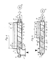
- Figures 1 and 3 schematically show a discharge apparatus comprising an inlet unit 1 and a screw discharging unit 2.
- the screw discharging unit 2 comprises an elongate screw housing 3 with a cylindrical casing wall 4 and a screw 5 rotatably mounted in the screw housing.
- the screw housing 3 has an inlet end 6 which is in direct communication with the inlet unit 1.
- the inlet unit is provided with or connected to a suitable pump (not shown) for supplying material to the screw discharging unit at a desired flow.
- a volumetric pump is preferably used.
- the screw 5 is supported by two opposing shafts 7, 8, axially aligned with each other and extending through bearings 9, one shaft 8 being connected to a motor 10 for rotation of the screw about its longitudinal axis 11.
- the screw discharging unit 2 is provided with an outlet in the casing wall 4 in the form of an elongate, narrow slot or aperture 12 running parallel to the longitudinal axis 11 of the screw and extending along the entire length of the screw. At least the width of the aperture may be adjustable to adapt the aperture area to different operating conditions.
- the screw 5 comprises a central core 13 and a screw blade 14 carried by the core and having a predetermined pitch.
- the diameter of the screw core 13 increases in the direction from the inlet end 6.
- the core 13 of the screw and casing wall 4 thus define a space or chamber 16 having a substantially annular cross section area (Figure 3) which decreases in the direction of feed of the screw seen from the inlet end 6 to the end located downstream of the screw, i.e. the decrease of the cross section area is to be found within the length of the aperture 12 (said cross section area is interrupted by the screw blade 14, but can be generally termed annular).
- the outer edge 15 of the screw blade has constant radius and is located near the inner surface of the casing wall 4 for sealing cooperation with each other.
- the effective height of the screw blade 14 above the surface of the core 13 will decrease correspondingly from the inlet end 6.
- the screw core is parabolic in shape, but it may alternatively be a truncated cone. Seen in longitudinal section, therefore, the outline of the core shown describes an exponential curve, whereas the outline of a truncated cone core is rectilinear.
- said cross section area approaches the value zero at the end of the aperture 12 facing away from the inlet 6.
- the discharge apparatus is provided along the length of the aperture 12 with a nozzle 17 having two opposing walls 18, 19 which define a channel 20 communicating with the aperture 12.
- the material is supplied to the screw discharging unit at a sufficient rate to maintain said space 16 continuously full of material.
- a discharge apparatus according to the invention used as a headbox provides controlled discharge of the material per unit length of the discharge aperture.
- the screw blade has a constant pitch.
- Figure 4 shows a modified embodiment of the screw 5 wherein the screw blade 26 has a successively decreasing pitch in the direction of feed.
- FIG 2 schematically shows a second embodiment of a discharge apparatus according to the invention, comprising an inlet unit 21 and a screw discharging unit 22 axially aligned therewith, the latter being substantially equivalent to that shown in Figure 1 apart from its length.
- the same reference numbers used in the figures therefore denote corresponding parts.
- the inlet unit 21 includes a dosing screw which is in direct communication with the screw discharging unit 22 and is provided with an inlet housing and a screw 23 having constant pitch on the screw blade 24 and a core 25 with constant diameter.
- the cores 13 and 25 of the screws 5 and 23, respectively, are permanently joined together to provide an integral, rotating screw unit.
- the inlet unit 21 may suitably be supplemented with means for removing air from the material before it reaches the screw discharging unit 22 itself.
- the casing wall of the inlet unit 21 is thus provided at the top with a suitable valve through which the air collected is removed.
- a suitable valve through which the air collected is removed.
- Such a compression can be achieved by giving the screw blade in the inlet unit a decreasing pitch and/or giving the core an increasing diameter in the direction of the screw discharging unit.
- Figure 5 illustrates a modification of the inlet unit 21 as indicated wherein the core 27 of the screw 23 is formed with an increasing diameter in the direction of the screw discharging unit. The collected air is removed through a valve connection 28.
- a screw discharging unit according to the invention which has an aperture with a length of 200 cm and is supplied with material in an amount of 2000 liters /min, will discharge the material in a volume per unit time and unit length of 10 liters/min.cm at each value of d x in accordance with the above equations.
- the discharge apparatus according to the invention is particularly useful as a headbox for a paper machine where it is of the utmost importance that the stock is discharged with a uniform flow across the web being formed.
- An essential advantage is that the stock can thus be given a higher fiber concentration, up to 9-12%, for instance, than has been possible in headboxes previously used.
- the discharge apparatus can also be used in drum presses to provide a uniform flow of material per unit width with respect to the web of material in the drum press. Such drum presses are used to dewater wet bark or a suspension of fiber material such as peat, for instance, and produce more uniform dewatering when equipped with a discharge apparatus according to the inveniton.
- the discharge apparatus according to the invention can be used to feed out any type of material in particle form and liquid form and mixtures thereof, which materials can be transported in a mechanical way.
- the two walls 18, 19 form lips of the nozzle 17, e.g. upper and lower lips.
- An advantage directly resultant from the invention is that no reinforcing means such as radial stiffening fins, for instance, need be arranged on the lips, nor any throttle means to regulate the outlet slot of the nozzle and thus the flow, since the discharge apparatus per se provides a controlled supply so that the material is fed out at the same volume per unit time and per unit length of the aperture, even if the nozzle channel changes.
- the distance between the lips towards the discharge gap is constant.
- the nozzle is designed for a radial flow of material.
- the lips may converge towards the outlet slot.
- the nozzle may be arranged for tangential discharge of the material from aperture 12, in which case two discharge apparatuses according to the invention, with such tangential nozzles, may be arranged close together to produce a paper web consisting of two layers.
- the nozzles may be built as a unit so that one lip is common for forming an intermediate lip, or alternatively they may be arranged at a predetermined distance from each other such that the nozzles form a narrow gap between them for the supply of air between the two layers being discharged.
- a plastic foil may be arranged in the air gap, if desired.
Landscapes
- Paper (AREA)
- Screw Conveyors (AREA)
- Coating Apparatus (AREA)
- Extrusion Moulding Of Plastics Or The Like (AREA)
- Formation And Processing Of Food Products (AREA)
- Saccharide Compounds (AREA)
- Pharmaceuticals Containing Other Organic And Inorganic Compounds (AREA)
- Compounds Of Unknown Constitution (AREA)
Priority Applications (1)
| Application Number | Priority Date | Filing Date | Title |
|---|---|---|---|
| AT84109712T ATE34792T1 (de) | 1983-09-16 | 1984-08-16 | Entleerungsvorrichtung fuer materialien. |
Applications Claiming Priority (2)
| Application Number | Priority Date | Filing Date | Title |
|---|---|---|---|
| SE8304979 | 1983-09-16 | ||
| SE8304979A SE448009B (sv) | 1983-09-16 | 1983-09-16 | Anordning for utmatning av material |
Publications (3)
| Publication Number | Publication Date |
|---|---|
| EP0135146A2 true EP0135146A2 (fr) | 1985-03-27 |
| EP0135146A3 EP0135146A3 (en) | 1985-10-09 |
| EP0135146B1 EP0135146B1 (fr) | 1988-06-01 |
Family
ID=20352514
Family Applications (1)
| Application Number | Title | Priority Date | Filing Date |
|---|---|---|---|
| EP84109712A Expired EP0135146B1 (fr) | 1983-09-16 | 1984-08-16 | Dispositif pour le déchargement de matières |
Country Status (7)
| Country | Link |
|---|---|
| US (1) | US4559104A (fr) |
| EP (1) | EP0135146B1 (fr) |
| AT (1) | ATE34792T1 (fr) |
| CA (1) | CA1237310A (fr) |
| DE (1) | DE3471706D1 (fr) |
| FI (1) | FI79873C (fr) |
| SE (1) | SE448009B (fr) |
Cited By (2)
| Publication number | Priority date | Publication date | Assignee | Title |
|---|---|---|---|---|
| DE10327193A1 (de) * | 2003-06-17 | 2005-01-13 | Voith Paper Patent Gmbh | Zuführeinrichtung |
| WO2013041338A1 (fr) * | 2011-09-22 | 2013-03-28 | Voith Patent Gmbh | Dispositif de distribution transversale d'une caisse de tête pour une machine de production d'une bande de matière fibreuse |
Families Citing this family (13)
| Publication number | Priority date | Publication date | Assignee | Title |
|---|---|---|---|---|
| SE454187B (sv) * | 1985-10-31 | 1988-04-11 | Kamyr Ab | Apparat for behandling av fibermaterial |
| US4854847A (en) * | 1988-07-11 | 1989-08-08 | Mendoza Fausto C | Tortilla dough forming machine |
| US5591336A (en) * | 1988-10-28 | 1997-01-07 | The Black Clawson Company | Apparatus for dewatering and or washing papermaking stock |
| US5304331A (en) * | 1992-07-23 | 1994-04-19 | Minnesota Mining And Manufacturing Company | Method and apparatus for extruding bingham plastic-type materials |
| SE504504C2 (sv) * | 1995-06-16 | 1997-02-24 | Conny Andersson | Förfarande och anordning för homogenisering av massgods |
| US5996855A (en) * | 1998-02-27 | 1999-12-07 | Material Sciences Corporation | Cross-feed auger and method |
| SE516335C2 (sv) * | 2001-01-26 | 2001-12-17 | Kvaerner Pulping Tech | Fördelningsanordning för utmatning av cellulosamassa i form av en massabana |
| ITVI20020048A1 (it) * | 2002-03-19 | 2003-09-19 | Comer Spa | Propulsore per l'agitazione di sospensioni di solidi all'interno di una vasca di trattamento |
| EP1400337B1 (fr) * | 2002-09-20 | 2007-08-22 | Basf Aktiengesellschaft | Dispositif et procédé d'extrusion de matières thermoplastiques et utilisation du dispositif |
| SE532366C2 (sv) * | 2008-04-23 | 2009-12-22 | Metso Paper Inc | Fördelningsanordning för utmatning av cellulosamassa |
| SE533686C2 (sv) * | 2009-04-09 | 2010-12-07 | Andritz Oy | Press för avvattning av en suspension, samt sätt för rengöring av denna |
| JP4990381B2 (ja) * | 2010-04-15 | 2012-08-01 | シャープ株式会社 | トナー排出装置、トナーカートリッジ、および画像形成装置 |
| JP5171890B2 (ja) * | 2010-06-23 | 2013-03-27 | シャープ株式会社 | 現像搬送装置およびそれを備えた現像装置、トナーカートリッジおよびクリーニングユニット |
Citations (2)
| Publication number | Priority date | Publication date | Assignee | Title |
|---|---|---|---|---|
| LU38870A1 (fr) * | 1959-06-27 | 1960-08-24 | ||
| US3217358A (en) * | 1964-08-19 | 1965-11-16 | Kihara Eigo | Flat die device for molding plastic members |
Family Cites Families (13)
| Publication number | Priority date | Publication date | Assignee | Title |
|---|---|---|---|---|
| US838686A (en) * | 1905-12-28 | 1906-12-18 | Alfred Wells Case | Machine for making pulp-board. |
| BE436163A (fr) * | 1938-08-30 | 1900-01-01 | ||
| US2504787A (en) * | 1947-08-01 | 1950-04-18 | Robert G Bailey | Distributing device |
| US2929449A (en) * | 1955-08-22 | 1960-03-22 | Auglo Paper Products Ltd | Fluid flow distribution devices |
| US3051233A (en) * | 1958-05-01 | 1962-08-28 | Black Clawson Co | Paper machinery |
| US3067815A (en) * | 1958-05-09 | 1962-12-11 | Voith Gmbh J M | Suspension distributing system |
| US3061008A (en) * | 1959-05-18 | 1962-10-30 | Beloit Iron Works | Stock flow distributor |
| US3137895A (en) * | 1961-09-25 | 1964-06-23 | Hagedorn & Co Ag A | Rotating attachment for extruding apparatus |
| US3559561A (en) * | 1964-07-07 | 1971-02-02 | Gen Mills Inc | Auger outlet extension |
| US3563853A (en) * | 1968-08-30 | 1971-02-16 | Fair Albert E H | Stock distributor |
| US3754847A (en) * | 1970-07-23 | 1973-08-28 | Ikegai Iron Works Ltd | Flat die for extruding laminated synthetic resin sheets |
| JPS4985151A (fr) * | 1972-12-07 | 1974-08-15 | ||
| US4112519A (en) * | 1976-07-08 | 1978-09-05 | Hpm Corporation | Vented injection molding machine and method |
-
1983
- 1983-09-16 SE SE8304979A patent/SE448009B/sv not_active IP Right Cessation
-
1984
- 1984-08-16 DE DE8484109712T patent/DE3471706D1/de not_active Expired
- 1984-08-16 AT AT84109712T patent/ATE34792T1/de not_active IP Right Cessation
- 1984-08-16 EP EP84109712A patent/EP0135146B1/fr not_active Expired
- 1984-08-27 US US06/644,246 patent/US4559104A/en not_active Expired - Lifetime
- 1984-08-28 CA CA000461934A patent/CA1237310A/fr not_active Expired
- 1984-09-05 FI FI843463A patent/FI79873C/fi not_active IP Right Cessation
Patent Citations (2)
| Publication number | Priority date | Publication date | Assignee | Title |
|---|---|---|---|---|
| LU38870A1 (fr) * | 1959-06-27 | 1960-08-24 | ||
| US3217358A (en) * | 1964-08-19 | 1965-11-16 | Kihara Eigo | Flat die device for molding plastic members |
Cited By (2)
| Publication number | Priority date | Publication date | Assignee | Title |
|---|---|---|---|---|
| DE10327193A1 (de) * | 2003-06-17 | 2005-01-13 | Voith Paper Patent Gmbh | Zuführeinrichtung |
| WO2013041338A1 (fr) * | 2011-09-22 | 2013-03-28 | Voith Patent Gmbh | Dispositif de distribution transversale d'une caisse de tête pour une machine de production d'une bande de matière fibreuse |
Also Published As
| Publication number | Publication date |
|---|---|
| FI79873C (fi) | 1990-03-12 |
| US4559104A (en) | 1985-12-17 |
| EP0135146A3 (en) | 1985-10-09 |
| CA1237310A (fr) | 1988-05-31 |
| SE8304979D0 (sv) | 1983-09-16 |
| FI79873B (fi) | 1989-11-30 |
| SE8304979L (sv) | 1985-03-17 |
| SE448009B (sv) | 1987-01-12 |
| DE3471706D1 (en) | 1988-07-07 |
| FI843463A (fi) | 1985-03-17 |
| ATE34792T1 (de) | 1988-06-15 |
| EP0135146B1 (fr) | 1988-06-01 |
| FI843463A0 (fi) | 1984-09-05 |
Similar Documents
| Publication | Publication Date | Title |
|---|---|---|
| US4559104A (en) | Apparatus for discharging material | |
| US8025761B2 (en) | Method for degassing and supplying a fibrous suspension to a headbox or a filter device and degassing device | |
| US5601192A (en) | Pressure sorter for fiber suspensions | |
| US4396502A (en) | Screening apparatus for a papermaking machine | |
| FI77274C (fi) | Foerfarande och anordning foer framstaellning av fibermassa. | |
| US4589923A (en) | Apparatus for removing liquid from fibrous materials | |
| EP0136000B1 (fr) | Machine à papier | |
| CA1154403A (fr) | Pompe et filtre a pate non pulse | |
| US4213823A (en) | Paper making machine screen with staggered foils | |
| US3051233A (en) | Paper machinery | |
| FI88528C (fi) | Anordning foer urvattning och raffinering av fibermassasuspensioner | |
| JPS5823985A (ja) | 抄紙機のワイヤ−部 | |
| US5968315A (en) | Process and apparatus for screening a fibre suspension in a pressurized screen having a rotating screen-drum | |
| RU2042756C1 (ru) | Напорный ящик для распределения волокнистой массы концентрацией 6 - 15% на устройстве для формования полотна | |
| EP0376446A2 (fr) | Epaississeur à 3 rouleaux pour pâte à papier et son utilisation | |
| CA1060246A (fr) | Chapeau d'aeration antiturbulence | |
| US3119734A (en) | Stock inlet and headbox for paper making machines | |
| US6461479B1 (en) | Process and device for distributing a pulp suspension, particularly at medium consistency | |
| US2881668A (en) | Paper forming section | |
| US3459121A (en) | Slurry feeder | |
| EP0067912B1 (fr) | Dispositif de tamisage pour pâte à papier et un procédé pour le traitement du pâte à papier | |
| JP2722027B2 (ja) | 円網抄紙機における供給紙料液の流量調整装置 | |
| EP0438092A1 (fr) | Dispositif pour l'épaississement de suspension fibreuse | |
| US5160584A (en) | High consistency sheet former | |
| EP1115945B1 (fr) | Procede et dispositif de lavage de melange de pate a fibres |
Legal Events
| Date | Code | Title | Description |
|---|---|---|---|
| PUAI | Public reference made under article 153(3) epc to a published international application that has entered the european phase |
Free format text: ORIGINAL CODE: 0009012 |
|
| AK | Designated contracting states |
Designated state(s): AT CH DE FR GB IT LI SE |
|
| PUAL | Search report despatched |
Free format text: ORIGINAL CODE: 0009013 |
|
| AK | Designated contracting states |
Designated state(s): AT CH DE FR GB IT LI SE |
|
| 17P | Request for examination filed |
Effective date: 19860114 |
|
| 17Q | First examination report despatched |
Effective date: 19870126 |
|
| RAP1 | Party data changed (applicant data changed or rights of an application transferred) |
Owner name: KAMYR AKTIEBOLAG |
|
| GRAA | (expected) grant |
Free format text: ORIGINAL CODE: 0009210 |
|
| AK | Designated contracting states |
Kind code of ref document: B1 Designated state(s): AT CH DE FR GB IT LI SE |
|
| PG25 | Lapsed in a contracting state [announced via postgrant information from national office to epo] |
Ref country code: LI Effective date: 19880601 Ref country code: IT Free format text: LAPSE BECAUSE OF FAILURE TO SUBMIT A TRANSLATION OF THE DESCRIPTION OR TO PAY THE FEE WITHIN THE PRESCRIBED TIME-LIMIT;WARNING: LAPSES OF ITALIAN PATENTS WITH EFFECTIVE DATE BEFORE 2007 MAY HAVE OCCURRED AT ANY TIME BEFORE 2007. THE CORRECT EFFECTIVE DATE MAY BE DIFFERENT FROM THE ONE RECORDED. Effective date: 19880601 Ref country code: CH Effective date: 19880601 |
|
| REF | Corresponds to: |
Ref document number: 34792 Country of ref document: AT Date of ref document: 19880615 Kind code of ref document: T |
|
| REF | Corresponds to: |
Ref document number: 3471706 Country of ref document: DE Date of ref document: 19880707 |
|
| ET | Fr: translation filed | ||
| REG | Reference to a national code |
Ref country code: CH Ref legal event code: PL |
|
| PLBE | No opposition filed within time limit |
Free format text: ORIGINAL CODE: 0009261 |
|
| STAA | Information on the status of an ep patent application or granted ep patent |
Free format text: STATUS: NO OPPOSITION FILED WITHIN TIME LIMIT |
|
| 26N | No opposition filed | ||
| PG25 | Lapsed in a contracting state [announced via postgrant information from national office to epo] |
Ref country code: GB Effective date: 19890816 |
|
| GBPC | Gb: european patent ceased through non-payment of renewal fee | ||
| EAL | Se: european patent in force in sweden |
Ref document number: 84109712.4 |
|
| PGFP | Annual fee paid to national office [announced via postgrant information from national office to epo] |
Ref country code: SE Payment date: 19970820 Year of fee payment: 14 |
|
| PG25 | Lapsed in a contracting state [announced via postgrant information from national office to epo] |
Ref country code: SE Free format text: LAPSE BECAUSE OF NON-PAYMENT OF DUE FEES Effective date: 19980817 |
|
| EUG | Se: european patent has lapsed |
Ref document number: 84109712.4 |
|
| PGFP | Annual fee paid to national office [announced via postgrant information from national office to epo] |
Ref country code: AT Payment date: 20030729 Year of fee payment: 20 |
|
| PGFP | Annual fee paid to national office [announced via postgrant information from national office to epo] |
Ref country code: DE Payment date: 20030805 Year of fee payment: 20 |
|
| PGFP | Annual fee paid to national office [announced via postgrant information from national office to epo] |
Ref country code: FR Payment date: 20030813 Year of fee payment: 20 |
|
| PG25 | Lapsed in a contracting state [announced via postgrant information from national office to epo] |
Ref country code: AT Free format text: LAPSE BECAUSE OF EXPIRATION OF PROTECTION Effective date: 20040816 |