EP0134431A2 - Procédé thermodynamique approchant le cycle d'Ericsson - Google Patents
Procédé thermodynamique approchant le cycle d'Ericsson Download PDFInfo
- Publication number
- EP0134431A2 EP0134431A2 EP84106748A EP84106748A EP0134431A2 EP 0134431 A2 EP0134431 A2 EP 0134431A2 EP 84106748 A EP84106748 A EP 84106748A EP 84106748 A EP84106748 A EP 84106748A EP 0134431 A2 EP0134431 A2 EP 0134431A2
- Authority
- EP
- European Patent Office
- Prior art keywords
- heat
- temperature
- energy
- pressure
- thermal
- Prior art date
- Legal status (The legal status is an assumption and is not a legal conclusion. Google has not performed a legal analysis and makes no representation as to the accuracy of the status listed.)
- Granted
Links
Images
Classifications
-
- F—MECHANICAL ENGINEERING; LIGHTING; HEATING; WEAPONS; BLASTING
- F01—MACHINES OR ENGINES IN GENERAL; ENGINE PLANTS IN GENERAL; STEAM ENGINES
- F01K—STEAM ENGINE PLANTS; STEAM ACCUMULATORS; ENGINE PLANTS NOT OTHERWISE PROVIDED FOR; ENGINES USING SPECIAL WORKING FLUIDS OR CYCLES
- F01K25/00—Plants or engines characterised by use of special working fluids, not otherwise provided for; Plants operating in closed cycles and not otherwise provided for
- F01K25/06—Plants or engines characterised by use of special working fluids, not otherwise provided for; Plants operating in closed cycles and not otherwise provided for using mixtures of different fluids
-
- F—MECHANICAL ENGINEERING; LIGHTING; HEATING; WEAPONS; BLASTING
- F02—COMBUSTION ENGINES; HOT-GAS OR COMBUSTION-PRODUCT ENGINE PLANTS
- F02G—HOT GAS OR COMBUSTION-PRODUCT POSITIVE-DISPLACEMENT ENGINE PLANTS; USE OF WASTE HEAT OF COMBUSTION ENGINES; NOT OTHERWISE PROVIDED FOR
- F02G2250/00—Special cycles or special engines
- F02G2250/09—Carnot cycles in general
Definitions
- the invention relates to a method for converting thermal energy into mechanical energy with the aim of improving its efficiency to approximate the Carnot process.
- the process consists on the one hand of two isothermal conversions by taking up or giving off thermal energy at the respective temperature levels of the heat source or of the heat outflow, and on the other hand of two isobaric conversions (heat exchange) with identical mean heat capacity (same slope of the curves), in which the Process fluid in two separate stages (heating or cooling) exchanges heat with itself.
- the basic condition here is that the temperature levels of the heat source or the heat outflow are sufficiently separated from one another to ensure a sufficiently high absolute value of the heat converted into mechanical energy.
- an additional condition can be introduced, namely that the pressure values mentioned should also be similar to atmospheric pressure.
- the boiling point of the less volatile component should be close to the temperature level of the heat source, while the boiling point of the more volatile component should be close to the temperature level of the heat flow.
- the substances to be used as process fluid can be miscible or immiscible in the liquid state.
- the vapors are fed into an isobaric heat exchanger, where they give off energy and cool down, where they also progressively condense the vapors from the components with a higher boiling point, so that a certain saturation mixture (liquid / vapor) of the components mentioned is obtained at each temperature level corresponds.
- This cooling takes place up to a temperature similar to the heat discharge temperature.
- the fluid leaves the heat exchanger, the vapor component mainly consisting of the component with the lowest boiling point - that is, the most volatile component.
- the other zone of the isobaric exchanger completely evaporates the component with the lowest boiling point at the highest process pressure values and the corresponding saturation temperature.
- This steam causes the progressive evaporation of the other components through the temperature rise of the mixture caused by the absorbed heat until the molar saturation is reached for the individual temperature levels.
- the process continues until it evaporates completely all components at the highest heat exchanger outlet temperature (generator inlet), with the exception of the component with the highest boiling point, which is in the liquid phase and is only completely evaporated in the steam generator at the highest process temperature - as stated.
- the molar compositions of the vapor phases at the respective temperatures are also quite similar, which in turn means that the mean specific heat is very similar to the isobaric conversion of the heat absorption and release in the entire temperature range.
- the gradient is minimal thanks to the small slope of the isobaric curves on both sides of the heat exchanger (very high mean specific heat values), which is due to the continuous condensation and evaporation, as already stated.
- the fluids mentioned were chosen mainly because of their easy procurement, their low costs and the great experience in their use in heat transfer processes. Nonetheless, the Fluidum D-A has one major disadvantage, which is its thermal stability range. Although this is relatively high (over 400 ° C according to the manufacturer's information) and enables easy regeneration, this also limits the highest value of the process heat to this temperature and thus also the absolute conversion efficiency (if the heat source delivers or enables higher temperatures). Of course, this disadvantage does not arise when using fluids with a higher thermal stability.
- the distilled water as a more volatile process fluid, does not appear to meet the process conditions. However, it is a composite with a smaller molecular mass and therefore also with a very high latent heat of the phase change under conditions which are within the working range of the critical temperature with respect to the mean specific heat of the liquefied fluids. And therefore it causes the slope of the heating isobars of said liquid phase to be very high. So is practical - within limits called - these isobars the isoenzyme tro p een curve in the context of the process sequence very close, because of the same the other isobaric curves are much smaller climbs on.
- the example shown can thus be regarded as a permissible alternative to the basic method mentioned, in which the isobaric heat exchange in the last stage has been replaced by isoentropic expansion in the turbine and isobaric heating of liquid water.
- FIG. 2 shows the corresponding diagram of the one-step process according to the invention.
- the isobars forming part of the diagram correspond to the mean specific conversion heat values.
- the areas shown in broken lines in FIG. 2 indicate the losses in the method according to the invention compared to the ideal process.
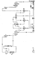
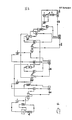
- FIGS. 3 and 4 A flow chart (FIGS. 3 and 4) has been created for the correct tracking of the examples.
- the resulting steam is saturated in D-A steam under the exit conditions at the steam generator outlet upon leaving this device.
- Liquid collection container (DL-I)
- the pipe outlet steam from the heat exchanger E-III flows into this turbine.
- This pressure corresponds to the saturation pressure of the water vapor at the lower process temperature of 298 ° K.
- Water is usually used as the cooling fluid and circulates in the housing of the heat exchanger.
- the container DL-IV is provided with the appropriate vacuum unit to create and maintain the necessary process conditions.
- the fluids chosen for the process example are selected according to the criteria already mentioned and are logically not optimal in order to achieve a good conversion efficiency under the given conditions.
- the method calculated as an example has not been optimized in any way.
- the pressure drops in the turbines were set quite arbitrarily and the minimum gradients in the heat exchangers could be optimized by approximation. So e.g. Under these conditions, the heat exchanger E-II could allow an additional water evaporation of about 1 kg / s.
- the absolute efficiency can be increased, namely by using a fluid that is thermally stable even at higher temperatures, or by using the same fluids from the example after an optimization of the process and by the provision of higher temperature levels in the first process stage (Brayton or Rankine cycle).
- the total losses from II and III evaluated for the existing process conditions are less than 1.5%.
- thermodynamic method allows a practical approximation of the conversion efficiency of the thermal energy contained between two specific and sufficiently separated temperature levels (heat source / heat discharge) to the conversion efficiency of a thermodynamic consisting of two isotherms (absorption and release) and two isobars Cycle that achieves the same efficiency as the Carnot cycle.
- thermodynamic consisting of two isotherms (absorption and release) and two isobars Cycle that achieves the same efficiency as the Carnot cycle.
Landscapes
- Engineering & Computer Science (AREA)
- Combustion & Propulsion (AREA)
- Mechanical Engineering (AREA)
- General Engineering & Computer Science (AREA)
- Chemical & Material Sciences (AREA)
- Engine Equipment That Uses Special Cycles (AREA)
- Steering Control In Accordance With Driving Conditions (AREA)
- Breeding Of Plants And Reproduction By Means Of Culturing (AREA)
- Transition And Organic Metals Composition Catalysts For Addition Polymerization (AREA)
- Diaphragms For Electromechanical Transducers (AREA)
- Adhesives Or Adhesive Processes (AREA)
- Presses And Accessory Devices Thereof (AREA)
- Power Steering Mechanism (AREA)
- Lubricants (AREA)
- Shaping Of Tube Ends By Bending Or Straightening (AREA)
- Production Of Liquid Hydrocarbon Mixture For Refining Petroleum (AREA)
Priority Applications (1)
| Application Number | Priority Date | Filing Date | Title |
|---|---|---|---|
| AT84106748T ATE68558T1 (de) | 1983-06-13 | 1984-06-13 | An den ericsson- prozess angenaehertes thermodynamisches verfahren. |
Applications Claiming Priority (2)
| Application Number | Priority Date | Filing Date | Title |
|---|---|---|---|
| ES523210A ES8605328A1 (es) | 1983-06-13 | 1983-06-13 | Un procedimiento de generacion de energia mecanica trabajando con una mezcla de fluidos de distintos puntos de ebullicion. |
| ES523210 | 1983-06-13 |
Publications (3)
| Publication Number | Publication Date |
|---|---|
| EP0134431A2 true EP0134431A2 (fr) | 1985-03-20 |
| EP0134431A3 EP0134431A3 (en) | 1985-11-27 |
| EP0134431B1 EP0134431B1 (fr) | 1991-10-16 |
Family
ID=8485855
Family Applications (1)
| Application Number | Title | Priority Date | Filing Date |
|---|---|---|---|
| EP84106748A Expired - Lifetime EP0134431B1 (fr) | 1983-06-13 | 1984-06-13 | Procédé thermodynamique approchant le cycle d'Ericsson |
Country Status (8)
| Country | Link |
|---|---|
| US (1) | US4691523A (fr) |
| EP (1) | EP0134431B1 (fr) |
| JP (1) | JPS6062608A (fr) |
| AT (1) | ATE68558T1 (fr) |
| CA (1) | CA1241845A (fr) |
| DE (1) | DE3485169D1 (fr) |
| ES (1) | ES8605328A1 (fr) |
| IL (1) | IL72045A (fr) |
Cited By (1)
| Publication number | Priority date | Publication date | Assignee | Title |
|---|---|---|---|---|
| AU595573B2 (en) * | 1986-01-08 | 1990-04-05 | Ormat Turbines (1965) Ltd. | Working fluid for rankine cycle power plant |
Families Citing this family (5)
| Publication number | Priority date | Publication date | Assignee | Title |
|---|---|---|---|---|
| JP2801477B2 (ja) * | 1992-09-22 | 1998-09-21 | キヤノン株式会社 | 画像信号処理装置 |
| JPH0794815B2 (ja) * | 1993-09-22 | 1995-10-11 | 佐賀大学長 | 温度差発電装置 |
| EP1433450A1 (fr) * | 2002-12-23 | 2004-06-30 | The Procter & Gamble Company | Compositions de polymère pour des structures perméables à la vapeur d'eau ayant une stabilité de structure et les structures contenant ces compositions |
| US8459031B2 (en) * | 2009-09-18 | 2013-06-11 | Kalex, Llc | Direct contact heat exchanger and methods for making and using same |
| FR3022296B1 (fr) * | 2014-06-16 | 2016-07-01 | Arkema France | Systeme de controle d'un cycle de rankine |
Citations (4)
| Publication number | Priority date | Publication date | Assignee | Title |
|---|---|---|---|---|
| DE1551260A1 (de) * | 1966-11-02 | 1970-03-19 | Siemens Ag | Verfahren zur Carnotisierung von Kreisprozessen fuer Dampfkraftanlagen und Anordnung zur Durchfuehrung des Verfahrens |
| FR2136120A1 (fr) * | 1971-04-01 | 1972-12-22 | Thermo Electron Corp | |
| FR2150123A5 (fr) * | 1971-08-17 | 1973-03-30 | Du Pont | |
| FR2499149A1 (fr) * | 1981-02-05 | 1982-08-06 | Linde Ag | Procede de transformation d'energie thermique en energie mecanique |
Family Cites Families (2)
| Publication number | Priority date | Publication date | Assignee | Title |
|---|---|---|---|---|
| US3006146A (en) * | 1958-09-19 | 1961-10-31 | Franklin Institute | Closed-cycle power plant |
| US4439988A (en) * | 1980-11-06 | 1984-04-03 | University Of Dayton | Rankine cycle ejector augmented turbine engine |
-
1983
- 1983-06-13 ES ES523210A patent/ES8605328A1/es not_active Expired
-
1984
- 1984-06-07 IL IL72045A patent/IL72045A/xx unknown
- 1984-06-11 CA CA000456293A patent/CA1241845A/fr not_active Expired
- 1984-06-13 JP JP59122901A patent/JPS6062608A/ja active Pending
- 1984-06-13 DE DE8484106748T patent/DE3485169D1/de not_active Expired - Lifetime
- 1984-06-13 AT AT84106748T patent/ATE68558T1/de not_active IP Right Cessation
- 1984-06-13 EP EP84106748A patent/EP0134431B1/fr not_active Expired - Lifetime
- 1984-06-13 US US06/620,364 patent/US4691523A/en not_active Expired - Fee Related
Patent Citations (4)
| Publication number | Priority date | Publication date | Assignee | Title |
|---|---|---|---|---|
| DE1551260A1 (de) * | 1966-11-02 | 1970-03-19 | Siemens Ag | Verfahren zur Carnotisierung von Kreisprozessen fuer Dampfkraftanlagen und Anordnung zur Durchfuehrung des Verfahrens |
| FR2136120A1 (fr) * | 1971-04-01 | 1972-12-22 | Thermo Electron Corp | |
| FR2150123A5 (fr) * | 1971-08-17 | 1973-03-30 | Du Pont | |
| FR2499149A1 (fr) * | 1981-02-05 | 1982-08-06 | Linde Ag | Procede de transformation d'energie thermique en energie mecanique |
Cited By (1)
| Publication number | Priority date | Publication date | Assignee | Title |
|---|---|---|---|---|
| AU595573B2 (en) * | 1986-01-08 | 1990-04-05 | Ormat Turbines (1965) Ltd. | Working fluid for rankine cycle power plant |
Also Published As
| Publication number | Publication date |
|---|---|
| ES8605328A1 (es) | 1986-04-01 |
| DE3485169D1 (de) | 1991-11-21 |
| EP0134431A3 (en) | 1985-11-27 |
| US4691523A (en) | 1987-09-08 |
| IL72045A (en) | 1993-01-14 |
| IL72045A0 (en) | 1984-10-31 |
| JPS6062608A (ja) | 1985-04-10 |
| CA1241845A (fr) | 1988-09-13 |
| ES523210A0 (es) | 1986-04-01 |
| ATE68558T1 (de) | 1991-11-15 |
| EP0134431B1 (fr) | 1991-10-16 |
Similar Documents
| Publication | Publication Date | Title |
|---|---|---|
| DE69627480T2 (de) | Turbinenkreislauf mit vorgewärmter injektion | |
| CH675749A5 (fr) | ||
| EP1706599B1 (fr) | Procédé et installation de conversion d'une énergie thermique résultante en énergie mécanique | |
| DE2730155B2 (de) | Verfahren zum Erzeugen von Kälte im Bereich kryogener Temperaturen | |
| WO1985004216A1 (fr) | Procede et installation destines a un cycle thermodynamique | |
| DE3225613C2 (de) | Absorptionswärmepumpensystem | |
| DE1805652B2 (de) | Verfahren zur Gewinnung von Frischwasser aus einer wäßrigen Salzlösung sowie Vorrichtung zur Durchführung des Verfahrens | |
| EP0134431A2 (fr) | Procédé thermodynamique approchant le cycle d'Ericsson | |
| DE1551234A1 (de) | Verfahren zur Umwandlung von Waerme in mechanische Energie | |
| EP0531293B1 (fr) | Procede thermique d'evaporation, de condensation et d'absorption, avec combinaison de ces processus | |
| DE2401556A1 (de) | Verfahren zur beheizung eines gebaeudes und heizungsanlage | |
| DE3129957C2 (fr) | ||
| DE3605466A1 (de) | Geschlossener gasturbinen-prozess im zweistoffverfahren | |
| DE19533249C1 (de) | Strömungsmaschine zur Erzeugung mechanischer Arbeit aus Wärmeenergie und ein Verfahren zur Erzeugung mechanischer Arbeit aus Wärmeenergie mit einer solchen Strömungsmaschine | |
| DE2248124A1 (de) | Destillationsanlage | |
| DE2919824A1 (de) | Waermepumpe | |
| DE3044580C2 (de) | Wärmepumpe und Verfahren zu ihrem Betrieb | |
| EP1270877B1 (fr) | Transformation de chaleur avec représsurisation | |
| DE2634192A1 (de) | Einrichtung zum heizen von gebaeuden | |
| DE3427219A1 (de) | Ueberkritischer dampfkraftmaschinen-kreisprozess | |
| DE3111174A1 (de) | Dampfstrahlkondensator mit fluessigkeitsabscheider, insbesondere fuer heiss- und kaltdampfkraftanlagen | |
| DE3233473A1 (de) | Waermekraftanlage mit "gas-dampf-kreisprozess", zur vollstaendigen umwandlung von waerme in mechanische arbeit | |
| AT397145B (de) | Einrichtung zur nutzung des wärmeinhaltes verflüssigter kältemittel in einem kreisprozess als abtau- und/oder kinetische energie bei wärmepumpenanlagen | |
| DE10118499B4 (de) | Verfahren zur Übertragung von Wärme und Wärmekollektor | |
| DE369516C (de) | Verfahren zur Erzeugung von Wasserdampf |
Legal Events
| Date | Code | Title | Description |
|---|---|---|---|
| PUAI | Public reference made under article 153(3) epc to a published international application that has entered the european phase |
Free format text: ORIGINAL CODE: 0009012 |
|
| AK | Designated contracting states |
Designated state(s): AT BE CH DE FR GB IT LI LU NL SE |
|
| PUAL | Search report despatched |
Free format text: ORIGINAL CODE: 0009013 |
|
| AK | Designated contracting states |
Designated state(s): AT BE CH DE FR GB IT LI LU NL SE |
|
| 17P | Request for examination filed |
Effective date: 19860429 |
|
| 17Q | First examination report despatched |
Effective date: 19861204 |
|
| GRAA | (expected) grant |
Free format text: ORIGINAL CODE: 0009210 |
|
| AK | Designated contracting states |
Kind code of ref document: B1 Designated state(s): AT BE CH DE FR GB IT LI LU NL SE |
|
| REF | Corresponds to: |
Ref document number: 68558 Country of ref document: AT Date of ref document: 19911115 Kind code of ref document: T |
|
| REF | Corresponds to: |
Ref document number: 3485169 Country of ref document: DE Date of ref document: 19911121 |
|
| ITF | It: translation for a ep patent filed |
Owner name: JACOBACCI & PERANI S.P.A. |
|
| GBT | Gb: translation of ep patent filed (gb section 77(6)(a)/1977) | ||
| ET | Fr: translation filed | ||
| PGFP | Annual fee paid to national office [announced via postgrant information from national office to epo] |
Ref country code: AT Payment date: 19920630 Year of fee payment: 9 |
|
| PGFP | Annual fee paid to national office [announced via postgrant information from national office to epo] |
Ref country code: CH Payment date: 19920721 Year of fee payment: 9 |
|
| PLBE | No opposition filed within time limit |
Free format text: ORIGINAL CODE: 0009261 |
|
| STAA | Information on the status of an ep patent application or granted ep patent |
Free format text: STATUS: NO OPPOSITION FILED WITHIN TIME LIMIT |
|
| 26N | No opposition filed | ||
| PGFP | Annual fee paid to national office [announced via postgrant information from national office to epo] |
Ref country code: GB Payment date: 19930611 Year of fee payment: 10 |
|
| PG25 | Lapsed in a contracting state [announced via postgrant information from national office to epo] |
Ref country code: AT Effective date: 19930613 |
|
| PGFP | Annual fee paid to national office [announced via postgrant information from national office to epo] |
Ref country code: SE Payment date: 19930614 Year of fee payment: 10 Ref country code: FR Payment date: 19930614 Year of fee payment: 10 |
|
| PGFP | Annual fee paid to national office [announced via postgrant information from national office to epo] |
Ref country code: BE Payment date: 19930621 Year of fee payment: 10 |
|
| PGFP | Annual fee paid to national office [announced via postgrant information from national office to epo] |
Ref country code: LU Payment date: 19930629 Year of fee payment: 10 |
|
| PG25 | Lapsed in a contracting state [announced via postgrant information from national office to epo] |
Ref country code: LI Effective date: 19930630 Ref country code: CH Effective date: 19930630 |
|
| PGFP | Annual fee paid to national office [announced via postgrant information from national office to epo] |
Ref country code: NL Payment date: 19930630 Year of fee payment: 10 |
|
| PGFP | Annual fee paid to national office [announced via postgrant information from national office to epo] |
Ref country code: DE Payment date: 19930709 Year of fee payment: 10 |
|
| EPTA | Lu: last paid annual fee | ||
| REG | Reference to a national code |
Ref country code: CH Ref legal event code: PL |
|
| PG25 | Lapsed in a contracting state [announced via postgrant information from national office to epo] |
Ref country code: LU Free format text: LAPSE BECAUSE OF NON-PAYMENT OF DUE FEES Effective date: 19940613 Ref country code: GB Effective date: 19940613 |
|
| PG25 | Lapsed in a contracting state [announced via postgrant information from national office to epo] |
Ref country code: SE Effective date: 19940614 |
|
| PG25 | Lapsed in a contracting state [announced via postgrant information from national office to epo] |
Ref country code: BE Effective date: 19940630 |
|
| BERE | Be: lapsed |
Owner name: MENDOZA ROSADO SERAFIN Effective date: 19940630 |
|
| PG25 | Lapsed in a contracting state [announced via postgrant information from national office to epo] |
Ref country code: NL Effective date: 19950101 |
|
| EUG | Se: european patent has lapsed |
Ref document number: 84106748.1 Effective date: 19950110 |
|
| GBPC | Gb: european patent ceased through non-payment of renewal fee |
Effective date: 19940613 |
|
| NLV4 | Nl: lapsed or anulled due to non-payment of the annual fee | ||
| PG25 | Lapsed in a contracting state [announced via postgrant information from national office to epo] |
Ref country code: FR Effective date: 19950228 |
|
| PG25 | Lapsed in a contracting state [announced via postgrant information from national office to epo] |
Ref country code: DE Effective date: 19950301 |
|
| EUG | Se: european patent has lapsed |
Ref document number: 84106748.1 |
|
| REG | Reference to a national code |
Ref country code: FR Ref legal event code: ST |