EP0134401A2 - Verfahren und Vorrichtung zum Prüfen der Verschleissfestigkeit und der Änderung des Aussehens von Konstruktionsteilen im Möbelbereich - Google Patents
Verfahren und Vorrichtung zum Prüfen der Verschleissfestigkeit und der Änderung des Aussehens von Konstruktionsteilen im Möbelbereich Download PDFInfo
- Publication number
- EP0134401A2 EP0134401A2 EP84105126A EP84105126A EP0134401A2 EP 0134401 A2 EP0134401 A2 EP 0134401A2 EP 84105126 A EP84105126 A EP 84105126A EP 84105126 A EP84105126 A EP 84105126A EP 0134401 A2 EP0134401 A2 EP 0134401A2
- Authority
- EP
- European Patent Office
- Prior art keywords
- drum
- members
- construction
- stress members
- wearing
- Prior art date
- Legal status (The legal status is an assumption and is not a legal conclusion. Google has not performed a legal analysis and makes no representation as to the accuracy of the status listed.)
- Withdrawn
Links
- 238000010276 construction Methods 0.000 title claims abstract description 62
- 238000012360 testing method Methods 0.000 title claims abstract description 37
- 238000000034 method Methods 0.000 title claims abstract description 15
- 239000000463 material Substances 0.000 claims abstract description 33
- 239000004744 fabric Substances 0.000 claims abstract description 13
- 239000004753 textile Substances 0.000 claims abstract description 13
- XLYOFNOQVPJJNP-UHFFFAOYSA-N water Substances O XLYOFNOQVPJJNP-UHFFFAOYSA-N 0.000 claims abstract description 13
- 239000002689 soil Substances 0.000 claims abstract description 11
- 239000010985 leather Substances 0.000 claims abstract description 9
- 239000004576 sand Substances 0.000 claims abstract description 9
- 229910001651 emery Inorganic materials 0.000 claims abstract description 6
- 239000011248 coating agent Substances 0.000 claims description 13
- 238000000576 coating method Methods 0.000 claims description 13
- 230000002093 peripheral effect Effects 0.000 claims description 10
- 239000003570 air Substances 0.000 claims description 6
- 229920003023 plastic Polymers 0.000 claims description 6
- 239000004033 plastic Substances 0.000 claims description 5
- 239000000725 suspension Substances 0.000 claims description 5
- 240000000491 Corchorus aestuans Species 0.000 claims description 4
- 235000011777 Corchorus aestuans Nutrition 0.000 claims description 4
- 235000010862 Corchorus capsularis Nutrition 0.000 claims description 4
- 230000002441 reversible effect Effects 0.000 claims description 4
- 239000006260 foam Substances 0.000 claims description 3
- 238000009434 installation Methods 0.000 claims description 3
- 238000004378 air conditioning Methods 0.000 claims description 2
- 238000002360 preparation method Methods 0.000 claims description 2
- 230000000284 resting effect Effects 0.000 claims description 2
- 238000005096 rolling process Methods 0.000 claims description 2
- 239000007787 solid Substances 0.000 claims description 2
- 238000009408 flooring Methods 0.000 claims 1
- 238000012546 transfer Methods 0.000 description 3
- 238000006073 displacement reaction Methods 0.000 description 2
- 238000003780 insertion Methods 0.000 description 2
- 230000037431 insertion Effects 0.000 description 2
- 238000007689 inspection Methods 0.000 description 2
- 229920005830 Polyurethane Foam Polymers 0.000 description 1
- 230000004323 axial length Effects 0.000 description 1
- 230000001427 coherent effect Effects 0.000 description 1
- 238000004891 communication Methods 0.000 description 1
- 230000003750 conditioning effect Effects 0.000 description 1
- 230000008602 contraction Effects 0.000 description 1
- 229920001971 elastomer Polymers 0.000 description 1
- 239000011496 polyurethane foam Substances 0.000 description 1
- 238000009877 rendering Methods 0.000 description 1
- 230000000717 retained effect Effects 0.000 description 1
- 239000005060 rubber Substances 0.000 description 1
Images
Classifications
-
- G—PHYSICS
- G01—MEASURING; TESTING
- G01M—TESTING STATIC OR DYNAMIC BALANCE OF MACHINES OR STRUCTURES; TESTING OF STRUCTURES OR APPARATUS, NOT OTHERWISE PROVIDED FOR
- G01M99/00—Subject matter not provided for in other groups of this subclass
- G01M99/001—Testing of furniture, e.g. seats or mattresses
-
- G—PHYSICS
- G01—MEASURING; TESTING
- G01N—INVESTIGATING OR ANALYSING MATERIALS BY DETERMINING THEIR CHEMICAL OR PHYSICAL PROPERTIES
- G01N3/00—Investigating strength properties of solid materials by application of mechanical stress
- G01N3/56—Investigating resistance to wear or abrasion
Definitions
- the invention relates to a method of reproducibly testing the resistance to wear and changes in appearance as well as the soil resistance of construction units within the furniture field with associated environments such as the domestic environment, offices, canteens, assembly halls, means for transport etc. in their normally used assembled state and in full size or optionally as scale models such as for instance for an article of furniture with an outer coating of textile and with one or more underlying layers over a frame.
- the invention also relates to an apparatus for carrying out the method.
- a number of various methods with associated apparatuses are known for testing separate qualities of the individual parts of a construction unit.
- a common problem for a number of these known methods and apparatuses is, however, that the test conditions deviate essentially in several respects from the actual conditions that the parts in question are subjected to in practice. This problem applies for instance to a number of useful qualities of the construction units mentioned above.
- the object of the invention is to provide a method and an apparatus for testing especially the wear resistance and change in appearance as well as the soil resistance of construction units within the furniture field with associated environments under conditions as far as possible corresponding to the use conditions in practice of said construction units, including especially their shape and combination with various materials.
- the method according to the invention is characterised by positioning the construction unit or parts thereof in its full construction secured on the inner peripheral surface of a rotatable, optionally reversible, large drum, and subsequently by subjecting said unit to the stress of stress members located within the drum and activated by the rotation of the drum in such a manner that they slide on, abut, and/ or are dragged across the construction unit, whereby the number of stresses or rotations of the drum necessary for producing a predetermined change in appearance of the construction unit by given test conditions are registered.
- the construction unit is tested in its normally used assembled state, whereby an expression close to the practice is obtained of the qualities of the assembled construction unit.
- test conditions are chosen such that results are obtained which correlate well with the changes in appearance arising in practice for the same construction unit, such as several simultaneously working stress members such as for instance substantially ball-shaped leather balls filled with air, water or sand and provided with a facing of wearing tapes having varying wearing qualities in response to the field of application for the tested construction unit, e.g. textile wearing materials for furniture surfaces for sitting or lying purposes and for instance emery cloth and/or sole materials for floor coverings.
- simultaneously working stress members such as for instance substantially ball-shaped leather balls filled with air, water or sand and provided with a facing of wearing tapes having varying wearing qualities in response to the field of application for the tested construction unit, e.g. textile wearing materials for furniture surfaces for sitting or lying purposes and for instance emery cloth and/or sole materials for floor coverings.
- An apparatus for reproducibly testing the resistance to wear and changes in appearance as well as the soil resistance of construction units within the furniture field with associated environments such as the domestic environment, offices, canteens, assembly halls, means of transport etc. in their normally used assembled state and in full size or optionally as scale models such as for instance for an article of furniture with an outer coating of textile and with one or more underlying layers over a frame, is according to the invention characterised in that it comprises a rotatable and optionally reversible, large drum supported by supporting means and comprising means for accurately adjusting the number of rotations of the drum and furthermore comprising a number of securing devices situated along the inner circumference of the drum for securing one or more construction units on each device as well as a number of stress members located within the drum.
- Such an apparatus renders it possible to a great extent to imitate the stresses arising in practice on the construction units in question. Furthermore the apparatus is very flexible with-respect to possible test conditions, and it can be used for testing several identical or differing units at the same time. In addition, the apparatus is of a sturdy construction and requires only little time for the testing.
- the drum may according to the invention be of an internal diameter of the magnitude 900-2000 mm, preferably 1000-1600 mm, especially 1200 mm.
- the drum may according to the invention be of an internal diameter of the magnitude 900-2000 mm, preferably 1000-1600 mm, especially 1200 mm.
- four seats or cushions with a 90° displacement along the periphery may be tested simultaneously in a drum of 1200 mm.
- the securing devices may according to the invention be radially adjustable. Furthermore, in order to make it easy to mount, inspect, and dismount the testing members, the securing devices may according to the invention be axially removable.
- the securing devices may thus be plates mounted so as to be radially adjustable on axially directed slide bars retainable and axially displaceable in fixed guides on the inner peripheral surface of the drum, said plates comprising fittings or the like means for the securing of the construction units.
- This embodiment turned out to be a useful embodiment of the securing devices, which facilitates the change between various construction units.
- a particularly flexible and relatively inexpensive type of stress members is according to the invention obtained by the stress members being wearing members loosely situated in the drum and freely falling at the rotation of said drum, said wearing members for instance being balls, bags or the like members solid or filled with air, water or sand and of a shape, size, weight, and coating defined in greater details such as for instance substantially ball-shaped, water-filled leather balls of a diameter of 200 t 10 mm, a weight of 2500 - 50 g, and optionally provided with wearing tapes of another coating material such as jute fabric, emery cloth or the like material.
- the stress members being wearing members loosely situated in the drum and freely falling at the rotation of said drum, said wearing members for instance being balls, bags or the like members solid or filled with air, water or sand and of a shape, size, weight, and coating defined in greater details such as for instance substantially ball-shaped, water-filled leather balls of a diameter of 200 t 10 mm, a weight of 2500 - 50 g, and optionally provided with wearing
- the stress members may furthermore according to the invention be coated with materials of a type used for soles, and the various stress members may be made of different coating materials, whereby a stress of the floor coating is obtained which is particularly close to practice.
- Stress members may according to the invention furthermore be provided which are suspended on a central suspension shaft in such a manner that they can be dragged across the construction units during the rotation of said units with the drum. In this manner a particular type of stresses is obtained which is particularly suited for constructions units in practice subjected to similar dragging stresses, e.g. door mats.
- a simple way of applying especially dragging or particular stresses may according to the invention be obtained by means of an axial rod projecting into the interior of the drum and comprising pendent wearing members such as strips of wearing material or brushes, balls or hose-shaped wearing members being dragged across the construction units during the rotation of said units with the drum. In this manner many different types of stresses can be carried out on the construction units.
- the stress members may be substantially cubic members of foam plastics and contain a standardized soiling preparation.
- the supporting means are support rollers mounted on a frame so as to run freely, the drum resting and rolling on said support rollers, a sturdy and simple support of the drum is obtained.
- the drum may according to the invention be driven by a driving motor pulling directly on a wheel on the central shaft projection of the drum through an endless band or a chain, which forms a simple and efficient power transfer and which furthermore allows an easy adjustment of the number of rotations of the drum.
- the adjusting means for the rotation of the drum comprise a programmed control unit allowing intermittent running, optionally at varying rates of rotation. As a result it is possible to program in advance the rates of rotation and running periods of a complete test program. As the adjusting means for the rotation of the drum are infinitely variable, an optional adjustment of the number of rotation is obtained.
- the drum used may according to the invention be substantially closed both at its peripheral surface and at its end surfaces, and it may comprise openings in its end surfaces allowing a connecting of the interior of the drum to an air conditioning installation. As a result it is possible to maintain a controlled climate within the drum during the testing.
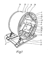
- FIG. 1 illustrates an apparatus according to the invention.
- the apparatus comprises a cylindrical drum 1, which can be made rotating about its own axis and which rests on four supporting means 2. These supporting means are shaped as freely running rollers individually mounted in brackets 12 supported by a rigid frame 11.
- the drum comprises a self-supporting relatively rigid mantle 13 strengtened on the outside by means of two hoops 14. These hoops 14 serve simultaneously as rails for the support rollers 2.
- the above drum furthermore comprises two end walls, viz. a rear end wall 26 and a front end wall 27, respectively.
- the drum is of an internal diameter of approx. 1200 mm and an axial length of approx. 650 mm.
- Each securing device 3 comprises a plate 6 mounted parallel to an axial plane for the drum 1 on glide bars 7.
- the construction unit 4 to be tested is mounted on the plate 6 with the testing surface facing the interior of the drum by means of fittings 10.
- the plate 6 is radially displaceable in such a manner that the surface of the construction unit 4 to be tested is substantially positioned at a predetermined distance from the axis of symmetry of the drum.
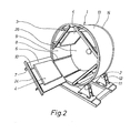
- the glide bars 7 mounted on the plate 6 are retained and axially displaceable in fixed guides 8 on the inner peripheral surface 9 of the drum in such a manner that the entire plate 6 with the construction unit 4 can be drawn outwards into a position outside the drum 1 by means of a handle 24, cf. Figure 2, whereby the mounting, the dismounting, and the inspection of.the construction unit 4 are essentially facilitated.
- the apparatus furthermore comprises a number of stress members 5 of varying shapes, some shapes appearing from the Figures 5a, b, c, and d.
- Figure 1 illustrates three such stress members 5 loosely situated in the drum 1 in a position typical for an idle drum.
- the stress members 5 shown are leather balls filled with water and provided with wearing tapes 15 in the form of jute fabric.
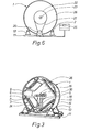
- FIG. 3 illustrates another type of stress members, viz. elongated wearing members in the form of bands 18 or long hoses 29 filled with sand, cf. the Figures 4 or 5c, and suspended on a central suspension shaft 16.
- the stress members 18, 29 are suspended in rings 30 rotatable about the suspension shaft 16 in such a manner that they cannot be wound about the shaft when said shaft rotates with the drum. * In this embodiment, the stress members are dragged across the construction units.
- the stress members 18, 29 can also be suspended on an axial rod 17 inserted through an opening 28 in the front end wall 27.
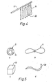
- Figure 5 illustrates examples of differently shaped stress members.
- Figure 5a illustrates the above ball-shaped stress members, which may be filled with either air, water or sand and be of different diameters, and the outer material of which for instance may be leather, plastics, rubber or textile optional- ly provided with bands of textile material, emery cloth or another material.
- Figure 5b illustrates a bag-shaped stress member for instance filled with water or sand.
- This stress member is provided with a contraction in the middle portion in such a manner that two coherent lumps are formed.
- the size and the outer material of the bag may be varied, and the bag can be more or less filled,
- Figure 5c illustrates a hose-shaped member, which can vary in size, material, and filling too.
- Figure 5d illustrates a substantially cubic member of foam plastics such as for instance polyurethane foam plastics suited for receiving and releasing great amounts of soil such as for instance standardized soil according to British standard. Such stress members allow a testing of the soil tendency of the construction units.
- foam plastics such as for instance polyurethane foam plastics suited for receiving and releasing great amounts of soil such as for instance standardized soil according to British standard.
- stress members allow a testing of the soil tendency of the construction units.
- the drum is made rotating by means of a driving motor 20, cf. Figure 6.
- This driving motor transfers its torque to a wheel 22 through power transferring means such as for instance an endless band 21.
- the wheel 22 is fixedly connected to the rear end wall 26 of the drum.
- the number of rotations of the drum is adjustable and controllable by means of a programmed control unit 25 adjustable to intermittent running of the drum at varying rates of rotation.
- the front end wall 27 of the drum is made of transparent plastics and comprises a central opening 28. This opening may be used for communication with a conditioning installation (not shown) controlling the temperature and/or the humidity within the drum,or it may be used for insertion of the stress members on an axial rod 17.
- the end wall is besides openable or detachable for an insertion and removal of the construction units 4.
- the construction units 4 When running a test, the construction units 4 are secured in the drum 1. Then the drum is provided with the selection of stress members 4 suitable for the test in question according to experience. Subsequently, the drum is made rotating at a suitable rate of rotation either stepwise a predetermined number of rotations at a time, where the construction units are inspected after each step, or a number of rotations of the drum determined in advance. Now the construction units are removed for a final inspection and for instance compared with standard samples. The tests run up till now have shown a good agreement with the wear patterns and changes in appearance known from use of the construction units in practice. Experience thus taught that a number of rotations for the drum of approx.
Landscapes
- Physics & Mathematics (AREA)
- General Physics & Mathematics (AREA)
- Health & Medical Sciences (AREA)
- Life Sciences & Earth Sciences (AREA)
- Chemical & Material Sciences (AREA)
- Analytical Chemistry (AREA)
- Biochemistry (AREA)
- General Health & Medical Sciences (AREA)
- Immunology (AREA)
- Pathology (AREA)
- Investigating Strength Of Materials By Application Of Mechanical Stress (AREA)
- Treatment Of Fiber Materials (AREA)
Applications Claiming Priority (2)
| Application Number | Priority Date | Filing Date | Title |
|---|---|---|---|
| DK2074/83 | 1983-05-10 | ||
| DK207483A DK149030C (da) | 1983-05-10 | 1983-05-10 | Fremgangsmaade til testning af konstruktionsenheder indenfor moebelomraadet med tilhoerende miljoeer i deres i praksis forekommende sammensatte tilstand og apparat til brug ved fremgangsmaaden |
Publications (2)
| Publication Number | Publication Date |
|---|---|
| EP0134401A2 true EP0134401A2 (de) | 1985-03-20 |
| EP0134401A3 EP0134401A3 (de) | 1987-03-11 |
Family
ID=8109899
Family Applications (1)
| Application Number | Title | Priority Date | Filing Date |
|---|---|---|---|
| EP84105126A Withdrawn EP0134401A3 (de) | 1983-05-10 | 1984-05-07 | Verfahren und Vorrichtung zum Prüfen der Verschleissfestigkeit und der Änderung des Aussehens von Konstruktionsteilen im Möbelbereich |
Country Status (4)
| Country | Link |
|---|---|
| US (1) | US4583392A (de) |
| EP (1) | EP0134401A3 (de) |
| CA (1) | CA1216172A (de) |
| DK (1) | DK149030C (de) |
Cited By (1)
| Publication number | Priority date | Publication date | Assignee | Title |
|---|---|---|---|---|
| CN105823616A (zh) * | 2015-01-04 | 2016-08-03 | 中国地震局地质研究所 | 推移质模拟器 |
Families Citing this family (8)
| Publication number | Priority date | Publication date | Assignee | Title |
|---|---|---|---|---|
| TWI444616B (zh) * | 2012-06-06 | 2014-07-11 | Univ Nat Taiwan Science Tech | 滾筒式水力衝擊磨耗量測裝置 |
| CN104132859B (zh) * | 2014-07-25 | 2017-03-01 | 谢彩红 | 一种行李箱出厂检验装置 |
| CN116660075B (zh) * | 2023-01-18 | 2024-06-04 | 江苏省纺织产品质量监督检验研究院 | 一种皮革耐磨性测试装置及使用方法 |
| CN117129357B (zh) * | 2023-08-01 | 2024-06-21 | 营口阿部配线有限公司 | 一种汽车线束性能检测设备 |
| CN117606969B (zh) * | 2024-01-17 | 2024-07-09 | 西安重装蒲白煤矿机械有限公司 | 一种基体涂层的表面耐磨度检测装置及检测方法 |
| US12372436B1 (en) * | 2024-01-22 | 2025-07-29 | Stress Engineering Services, Inc. | Rotational test apparatus and methods |
| CN119935713B (zh) * | 2024-12-31 | 2025-08-26 | 国家市场监督管理总局国家标准技术审评中心 | 纺织材料用磨损消耗自动化试验装置 |
| CN120275211B (zh) * | 2025-06-10 | 2025-08-22 | 山东非金属材料研究所 | 一种防弹衣翻滚预处理台架测试装置及使用方法 |
Family Cites Families (6)
| Publication number | Priority date | Publication date | Assignee | Title |
|---|---|---|---|---|
| US2590839A (en) * | 1946-11-20 | 1952-04-01 | Harry F Clapham | Fabric wear tester |
| US2797574A (en) * | 1955-02-14 | 1957-07-02 | Ralph A Rusca | Fabric abrader |
| SU151086A1 (ru) * | 1961-12-02 | 1962-11-30 | И.В. Петров | Машина дл испытани материалов на абразивное изнашивание |
| DE1302041B (de) * | 1966-03-30 | 1969-10-16 | Kern | Vorrichtung zum Pruefen der Abrasivitaet von Schleif-, Putz- und Poliermitteln |
| JPS5822127Y2 (ja) * | 1978-05-22 | 1983-05-11 | 須賀 蓊 | 金属の耐磨耗性試験機 |
| FR2519573A1 (fr) * | 1982-01-12 | 1983-07-18 | Bertin & Cie | Dispositif pour le poncage et/ou l'egrenage de pieces en bois |
-
1983
- 1983-05-10 DK DK207483A patent/DK149030C/da not_active IP Right Cessation
-
1984
- 1984-05-02 US US06/606,242 patent/US4583392A/en not_active Expired - Fee Related
- 1984-05-07 EP EP84105126A patent/EP0134401A3/de not_active Withdrawn
- 1984-05-09 CA CA000453891A patent/CA1216172A/en not_active Expired
Cited By (1)
| Publication number | Priority date | Publication date | Assignee | Title |
|---|---|---|---|---|
| CN105823616A (zh) * | 2015-01-04 | 2016-08-03 | 中国地震局地质研究所 | 推移质模拟器 |
Also Published As
| Publication number | Publication date |
|---|---|
| DK207483D0 (da) | 1983-05-10 |
| CA1216172A (en) | 1987-01-06 |
| DK207483A (da) | 1984-11-11 |
| DK149030B (da) | 1985-12-23 |
| DK149030C (da) | 1986-07-21 |
| EP0134401A3 (de) | 1987-03-11 |
| US4583392A (en) | 1986-04-22 |
Similar Documents
| Publication | Publication Date | Title |
|---|---|---|
| US4583392A (en) | Method of testing construction units within the furniture field with associated environments in their normally used assembled state and an apparatus to be used by the method | |
| US9212440B2 (en) | Natural wool pile fabric and method for making wool pile fabric | |
| BRPI0702562B1 (pt) | Aparelho para produzir tensão sobre uma superfície | |
| CN118937136A (zh) | 一种纺织品耐磨测试装置 | |
| US20170284915A1 (en) | Wear Test Device and Method | |
| CN113702163A (zh) | 一种纺织品耐磨度测试机 | |
| US2815658A (en) | Apparatus for testing fabric or the like | |
| US4630622A (en) | Hair rolling device | |
| EP0513192A1 (de) | Fahrzeugreinigungsapparat. | |
| CN111044401B (zh) | 一种自带真空室的便携式粉尘磨损测试装置 | |
| CN110542608B (zh) | 一种皮革弯折拉伸耐劳测试机 | |
| CN209546359U (zh) | 一种农业用稻谷晾晒设备 | |
| NZ200051A (en) | Drying cabinet:airflow guided to only pass through object to be dried | |
| CN218502573U (zh) | 一种粉料布料装置以及软管生产设备 | |
| CN207351393U (zh) | 一种材料厚度在线监测机构及自动削棉设备 | |
| US2399924A (en) | Device for grinding and polishing surfaces | |
| US1786437A (en) | Automatic tube-dusting device | |
| US157068A (en) | Improvement in machines for coating paper with emery, glass | |
| US1785690A (en) | Apparatus for and method of testing cords | |
| US3043134A (en) | Coated fabric flexing device | |
| AU9734601A (en) | Improved apparatus to stretch bands | |
| US2067863A (en) | Hosiery testing apparatus | |
| SU828084A1 (ru) | Устройство дл испытани текстильныхМАТЕРиАлОВ HA ОСыпАЕМОСТь НиТЕй | |
| CN121113823A (zh) | 一种基于微气候模拟的羽绒服透湿率检测装置 | |
| CN119198410B (zh) | 一种皮革饰品生产用智能检测设备 |
Legal Events
| Date | Code | Title | Description |
|---|---|---|---|
| PUAI | Public reference made under article 153(3) epc to a published international application that has entered the european phase |
Free format text: ORIGINAL CODE: 0009012 |
|
| AK | Designated contracting states |
Designated state(s): AT CH DE FR GB LI SE |
|
| PUAL | Search report despatched |
Free format text: ORIGINAL CODE: 0009013 |
|
| AK | Designated contracting states |
Kind code of ref document: A3 Designated state(s): AT CH DE FR GB LI SE |
|
| 17P | Request for examination filed |
Effective date: 19870909 |
|
| STAA | Information on the status of an ep patent application or granted ep patent |
Free format text: STATUS: THE APPLICATION IS DEEMED TO BE WITHDRAWN |
|
| 18D | Application deemed to be withdrawn |
Effective date: 19881130 |
|
| RIN1 | Information on inventor provided before grant (corrected) |
Inventor name: HOLMGREN, HOLGER Inventor name: WADLING, BO |