EP0134401A2 - A method of and apparatus for testing the resistance to wear and changes in appearance of construction units belonging to the furniture field - Google Patents
A method of and apparatus for testing the resistance to wear and changes in appearance of construction units belonging to the furniture field Download PDFInfo
- Publication number
- EP0134401A2 EP0134401A2 EP84105126A EP84105126A EP0134401A2 EP 0134401 A2 EP0134401 A2 EP 0134401A2 EP 84105126 A EP84105126 A EP 84105126A EP 84105126 A EP84105126 A EP 84105126A EP 0134401 A2 EP0134401 A2 EP 0134401A2
- Authority
- EP
- European Patent Office
- Prior art keywords
- drum
- members
- construction
- stress members
- wearing
- Prior art date
- Legal status (The legal status is an assumption and is not a legal conclusion. Google has not performed a legal analysis and makes no representation as to the accuracy of the status listed.)
- Withdrawn
Links
Images
Classifications
-
- G—PHYSICS
- G01—MEASURING; TESTING
- G01M—TESTING STATIC OR DYNAMIC BALANCE OF MACHINES OR STRUCTURES; TESTING OF STRUCTURES OR APPARATUS, NOT OTHERWISE PROVIDED FOR
- G01M99/00—Subject matter not provided for in other groups of this subclass
- G01M99/001—Testing of furniture, e.g. seats or mattresses
-
- G—PHYSICS
- G01—MEASURING; TESTING
- G01N—INVESTIGATING OR ANALYSING MATERIALS BY DETERMINING THEIR CHEMICAL OR PHYSICAL PROPERTIES
- G01N3/00—Investigating strength properties of solid materials by application of mechanical stress
- G01N3/56—Investigating resistance to wear or abrasion
Definitions
- the invention relates to a method of reproducibly testing the resistance to wear and changes in appearance as well as the soil resistance of construction units within the furniture field with associated environments such as the domestic environment, offices, canteens, assembly halls, means for transport etc. in their normally used assembled state and in full size or optionally as scale models such as for instance for an article of furniture with an outer coating of textile and with one or more underlying layers over a frame.
- the invention also relates to an apparatus for carrying out the method.
- a number of various methods with associated apparatuses are known for testing separate qualities of the individual parts of a construction unit.
- a common problem for a number of these known methods and apparatuses is, however, that the test conditions deviate essentially in several respects from the actual conditions that the parts in question are subjected to in practice. This problem applies for instance to a number of useful qualities of the construction units mentioned above.
- the object of the invention is to provide a method and an apparatus for testing especially the wear resistance and change in appearance as well as the soil resistance of construction units within the furniture field with associated environments under conditions as far as possible corresponding to the use conditions in practice of said construction units, including especially their shape and combination with various materials.
- the method according to the invention is characterised by positioning the construction unit or parts thereof in its full construction secured on the inner peripheral surface of a rotatable, optionally reversible, large drum, and subsequently by subjecting said unit to the stress of stress members located within the drum and activated by the rotation of the drum in such a manner that they slide on, abut, and/ or are dragged across the construction unit, whereby the number of stresses or rotations of the drum necessary for producing a predetermined change in appearance of the construction unit by given test conditions are registered.
- the construction unit is tested in its normally used assembled state, whereby an expression close to the practice is obtained of the qualities of the assembled construction unit.
- test conditions are chosen such that results are obtained which correlate well with the changes in appearance arising in practice for the same construction unit, such as several simultaneously working stress members such as for instance substantially ball-shaped leather balls filled with air, water or sand and provided with a facing of wearing tapes having varying wearing qualities in response to the field of application for the tested construction unit, e.g. textile wearing materials for furniture surfaces for sitting or lying purposes and for instance emery cloth and/or sole materials for floor coverings.
- simultaneously working stress members such as for instance substantially ball-shaped leather balls filled with air, water or sand and provided with a facing of wearing tapes having varying wearing qualities in response to the field of application for the tested construction unit, e.g. textile wearing materials for furniture surfaces for sitting or lying purposes and for instance emery cloth and/or sole materials for floor coverings.
- An apparatus for reproducibly testing the resistance to wear and changes in appearance as well as the soil resistance of construction units within the furniture field with associated environments such as the domestic environment, offices, canteens, assembly halls, means of transport etc. in their normally used assembled state and in full size or optionally as scale models such as for instance for an article of furniture with an outer coating of textile and with one or more underlying layers over a frame, is according to the invention characterised in that it comprises a rotatable and optionally reversible, large drum supported by supporting means and comprising means for accurately adjusting the number of rotations of the drum and furthermore comprising a number of securing devices situated along the inner circumference of the drum for securing one or more construction units on each device as well as a number of stress members located within the drum.
- Such an apparatus renders it possible to a great extent to imitate the stresses arising in practice on the construction units in question. Furthermore the apparatus is very flexible with-respect to possible test conditions, and it can be used for testing several identical or differing units at the same time. In addition, the apparatus is of a sturdy construction and requires only little time for the testing.
- the drum may according to the invention be of an internal diameter of the magnitude 900-2000 mm, preferably 1000-1600 mm, especially 1200 mm.
- the drum may according to the invention be of an internal diameter of the magnitude 900-2000 mm, preferably 1000-1600 mm, especially 1200 mm.
- four seats or cushions with a 90° displacement along the periphery may be tested simultaneously in a drum of 1200 mm.
- the securing devices may according to the invention be radially adjustable. Furthermore, in order to make it easy to mount, inspect, and dismount the testing members, the securing devices may according to the invention be axially removable.
- the securing devices may thus be plates mounted so as to be radially adjustable on axially directed slide bars retainable and axially displaceable in fixed guides on the inner peripheral surface of the drum, said plates comprising fittings or the like means for the securing of the construction units.
- This embodiment turned out to be a useful embodiment of the securing devices, which facilitates the change between various construction units.
- a particularly flexible and relatively inexpensive type of stress members is according to the invention obtained by the stress members being wearing members loosely situated in the drum and freely falling at the rotation of said drum, said wearing members for instance being balls, bags or the like members solid or filled with air, water or sand and of a shape, size, weight, and coating defined in greater details such as for instance substantially ball-shaped, water-filled leather balls of a diameter of 200 t 10 mm, a weight of 2500 - 50 g, and optionally provided with wearing tapes of another coating material such as jute fabric, emery cloth or the like material.
- the stress members being wearing members loosely situated in the drum and freely falling at the rotation of said drum, said wearing members for instance being balls, bags or the like members solid or filled with air, water or sand and of a shape, size, weight, and coating defined in greater details such as for instance substantially ball-shaped, water-filled leather balls of a diameter of 200 t 10 mm, a weight of 2500 - 50 g, and optionally provided with wearing
- the stress members may furthermore according to the invention be coated with materials of a type used for soles, and the various stress members may be made of different coating materials, whereby a stress of the floor coating is obtained which is particularly close to practice.
- Stress members may according to the invention furthermore be provided which are suspended on a central suspension shaft in such a manner that they can be dragged across the construction units during the rotation of said units with the drum. In this manner a particular type of stresses is obtained which is particularly suited for constructions units in practice subjected to similar dragging stresses, e.g. door mats.
- a simple way of applying especially dragging or particular stresses may according to the invention be obtained by means of an axial rod projecting into the interior of the drum and comprising pendent wearing members such as strips of wearing material or brushes, balls or hose-shaped wearing members being dragged across the construction units during the rotation of said units with the drum. In this manner many different types of stresses can be carried out on the construction units.
- the stress members may be substantially cubic members of foam plastics and contain a standardized soiling preparation.
- the supporting means are support rollers mounted on a frame so as to run freely, the drum resting and rolling on said support rollers, a sturdy and simple support of the drum is obtained.
- the drum may according to the invention be driven by a driving motor pulling directly on a wheel on the central shaft projection of the drum through an endless band or a chain, which forms a simple and efficient power transfer and which furthermore allows an easy adjustment of the number of rotations of the drum.
- the adjusting means for the rotation of the drum comprise a programmed control unit allowing intermittent running, optionally at varying rates of rotation. As a result it is possible to program in advance the rates of rotation and running periods of a complete test program. As the adjusting means for the rotation of the drum are infinitely variable, an optional adjustment of the number of rotation is obtained.
- the drum used may according to the invention be substantially closed both at its peripheral surface and at its end surfaces, and it may comprise openings in its end surfaces allowing a connecting of the interior of the drum to an air conditioning installation. As a result it is possible to maintain a controlled climate within the drum during the testing.
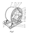
- FIG. 1 illustrates an apparatus according to the invention.
- the apparatus comprises a cylindrical drum 1, which can be made rotating about its own axis and which rests on four supporting means 2. These supporting means are shaped as freely running rollers individually mounted in brackets 12 supported by a rigid frame 11.
- the drum comprises a self-supporting relatively rigid mantle 13 strengtened on the outside by means of two hoops 14. These hoops 14 serve simultaneously as rails for the support rollers 2.
- the above drum furthermore comprises two end walls, viz. a rear end wall 26 and a front end wall 27, respectively.
- the drum is of an internal diameter of approx. 1200 mm and an axial length of approx. 650 mm.
- Each securing device 3 comprises a plate 6 mounted parallel to an axial plane for the drum 1 on glide bars 7.
- the construction unit 4 to be tested is mounted on the plate 6 with the testing surface facing the interior of the drum by means of fittings 10.
- the plate 6 is radially displaceable in such a manner that the surface of the construction unit 4 to be tested is substantially positioned at a predetermined distance from the axis of symmetry of the drum.
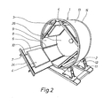
- the glide bars 7 mounted on the plate 6 are retained and axially displaceable in fixed guides 8 on the inner peripheral surface 9 of the drum in such a manner that the entire plate 6 with the construction unit 4 can be drawn outwards into a position outside the drum 1 by means of a handle 24, cf. Figure 2, whereby the mounting, the dismounting, and the inspection of.the construction unit 4 are essentially facilitated.
- the apparatus furthermore comprises a number of stress members 5 of varying shapes, some shapes appearing from the Figures 5a, b, c, and d.
- Figure 1 illustrates three such stress members 5 loosely situated in the drum 1 in a position typical for an idle drum.
- the stress members 5 shown are leather balls filled with water and provided with wearing tapes 15 in the form of jute fabric.
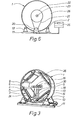
- FIG. 3 illustrates another type of stress members, viz. elongated wearing members in the form of bands 18 or long hoses 29 filled with sand, cf. the Figures 4 or 5c, and suspended on a central suspension shaft 16.
- the stress members 18, 29 are suspended in rings 30 rotatable about the suspension shaft 16 in such a manner that they cannot be wound about the shaft when said shaft rotates with the drum. * In this embodiment, the stress members are dragged across the construction units.
- the stress members 18, 29 can also be suspended on an axial rod 17 inserted through an opening 28 in the front end wall 27.
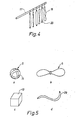
- Figure 5 illustrates examples of differently shaped stress members.
- Figure 5a illustrates the above ball-shaped stress members, which may be filled with either air, water or sand and be of different diameters, and the outer material of which for instance may be leather, plastics, rubber or textile optional- ly provided with bands of textile material, emery cloth or another material.
- Figure 5b illustrates a bag-shaped stress member for instance filled with water or sand.
- This stress member is provided with a contraction in the middle portion in such a manner that two coherent lumps are formed.
- the size and the outer material of the bag may be varied, and the bag can be more or less filled,
- Figure 5c illustrates a hose-shaped member, which can vary in size, material, and filling too.
- Figure 5d illustrates a substantially cubic member of foam plastics such as for instance polyurethane foam plastics suited for receiving and releasing great amounts of soil such as for instance standardized soil according to British standard. Such stress members allow a testing of the soil tendency of the construction units.
- foam plastics such as for instance polyurethane foam plastics suited for receiving and releasing great amounts of soil such as for instance standardized soil according to British standard.
- stress members allow a testing of the soil tendency of the construction units.
- the drum is made rotating by means of a driving motor 20, cf. Figure 6.
- This driving motor transfers its torque to a wheel 22 through power transferring means such as for instance an endless band 21.
- the wheel 22 is fixedly connected to the rear end wall 26 of the drum.
- the number of rotations of the drum is adjustable and controllable by means of a programmed control unit 25 adjustable to intermittent running of the drum at varying rates of rotation.
- the front end wall 27 of the drum is made of transparent plastics and comprises a central opening 28. This opening may be used for communication with a conditioning installation (not shown) controlling the temperature and/or the humidity within the drum,or it may be used for insertion of the stress members on an axial rod 17.
- the end wall is besides openable or detachable for an insertion and removal of the construction units 4.
- the construction units 4 When running a test, the construction units 4 are secured in the drum 1. Then the drum is provided with the selection of stress members 4 suitable for the test in question according to experience. Subsequently, the drum is made rotating at a suitable rate of rotation either stepwise a predetermined number of rotations at a time, where the construction units are inspected after each step, or a number of rotations of the drum determined in advance. Now the construction units are removed for a final inspection and for instance compared with standard samples. The tests run up till now have shown a good agreement with the wear patterns and changes in appearance known from use of the construction units in practice. Experience thus taught that a number of rotations for the drum of approx.
Landscapes
- Physics & Mathematics (AREA)
- General Physics & Mathematics (AREA)
- Health & Medical Sciences (AREA)
- Life Sciences & Earth Sciences (AREA)
- Chemical & Material Sciences (AREA)
- Analytical Chemistry (AREA)
- Biochemistry (AREA)
- General Health & Medical Sciences (AREA)
- Immunology (AREA)
- Pathology (AREA)
- Investigating Strength Of Materials By Application Of Mechanical Stress (AREA)
- Treatment Of Fiber Materials (AREA)
Abstract
Description
- The invention relates to a method of reproducibly testing the resistance to wear and changes in appearance as well as the soil resistance of construction units within the furniture field with associated environments such as the domestic environment, offices, canteens, assembly halls, means for transport etc. in their normally used assembled state and in full size or optionally as scale models such as for instance for an article of furniture with an outer coating of textile and with one or more underlying layers over a frame. The invention also relates to an apparatus for carrying out the method.
- The increasing use of new materials during recent years and the quick change to new constructions and combinations of materials within the furniture field with associated environments have caused an increasing demand for new testing methods and testing apparatuses rendering it possible to a higher extent than previously to carry out a test replacing with a good approximation a practice test of the assembled construction units.
- A number of various methods with associated apparatuses are known for testing separate qualities of the individual parts of a construction unit. A common problem for a number of these known methods and apparatuses is, however, that the test conditions deviate essentially in several respects from the actual conditions that the parts in question are subjected to in practice. This problem applies for instance to a number of useful qualities of the construction units mentioned above.
- Thus methods with associated apparatuses are used for instance for testing the resistance of textiles and other relatively soft, flexible fabrics to wear and change in appearance, where small samples of fabric in planar state are subjected to rubbing against a friction surface irrespective of the shapes in which the fabrics are used in practice and furthermore irrespective of the material layers that the fabrics are to be used together with.
- For testing the resistance to wear and change in appearance of carpets and soft floor coverings methods and apparatuses are furthermore known, whereby small drums are coated with the text material on the inside of the peripheral surface. Subsequently, the testing material is subjected to a freely falling four-footed wearing member in the drum during the rotation of said drum. The apparatuses used are, however, of a rather modest size with relatively small samples and wearing members. In addition the samples are mounted in a concavely bent position unnatural compared to the use in practice of said samples which implies that they are subjected to unnatural stresses. Moreover these apparatuses are not suited for testing other types of materials.
- The object of the invention is to provide a method and an apparatus for testing especially the wear resistance and change in appearance as well as the soil resistance of construction units within the furniture field with associated environments under conditions as far as possible corresponding to the use conditions in practice of said construction units, including especially their shape and combination with various materials.
- The method according to the invention is characterised by positioning the construction unit or parts thereof in its full construction secured on the inner peripheral surface of a rotatable, optionally reversible, large drum, and subsequently by subjecting said unit to the stress of stress members located within the drum and activated by the rotation of the drum in such a manner that they slide on, abut, and/ or are dragged across the construction unit, whereby the number of stresses or rotations of the drum necessary for producing a predetermined change in appearance of the construction unit by given test conditions are registered. In this manner the construction unit is tested in its normally used assembled state, whereby an expression close to the practice is obtained of the qualities of the assembled construction unit. Thus it is possible to test the stress of variations both in the outer material and in the underlying materials.
- In order to make the test results correspond as much as possible to the actual useful qualities, the test conditions are chosen such that results are obtained which correlate well with the changes in appearance arising in practice for the same construction unit, such as several simultaneously working stress members such as for instance substantially ball-shaped leather balls filled with air, water or sand and provided with a facing of wearing tapes having varying wearing qualities in response to the field of application for the tested construction unit, e.g. textile wearing materials for furniture surfaces for sitting or lying purposes and for instance emery cloth and/or sole materials for floor coverings.
- An apparatus according to the invention for reproducibly testing the resistance to wear and changes in appearance as well as the soil resistance of construction units within the furniture field with associated environments such as the domestic environment, offices, canteens, assembly halls, means of transport etc. in their normally used assembled state and in full size or optionally as scale models such as for instance for an article of furniture with an outer coating of textile and with one or more underlying layers over a frame, is according to the invention characterised in that it comprises a rotatable and optionally reversible, large drum supported by supporting means and comprising means for accurately adjusting the number of rotations of the drum and furthermore comprising a number of securing devices situated along the inner circumference of the drum for securing one or more construction units on each device as well as a number of stress members located within the drum. Such an apparatus renders it possible to a great extent to imitate the stresses arising in practice on the construction units in question. Furthermore the apparatus is very flexible with-respect to possible test conditions, and it can be used for testing several identical or differing units at the same time. In addition, the apparatus is of a sturdy construction and requires only little time for the testing.
- In order to ensure room for any size of all usual construction units in the drum or for sufficiently great parts thereof, whereby a testing close to the actual conditions is possible, the drum may according to the invention be of an internal diameter of the magnitude 900-2000 mm, preferably 1000-1600 mm, especially 1200 mm. Thus four seats or cushions with a 90° displacement along the periphery may be tested simultaneously in a drum of 1200 mm.
- In order always to maintain a constant distance between the testing members and consequently to maintain constant falling lengths or a constant movability of the stress members, the securing devices may according to the invention be radially adjustable. Furthermore, in order to make it easy to mount, inspect, and dismount the testing members, the securing devices may according to the invention be axially removable.
- According to the invention the securing devices may thus be plates mounted so as to be radially adjustable on axially directed slide bars retainable and axially displaceable in fixed guides on the inner peripheral surface of the drum, said plates comprising fittings or the like means for the securing of the construction units. This embodiment turned out to be a useful embodiment of the securing devices, which facilitates the change between various construction units.
- A particularly flexible and relatively inexpensive type of stress members is according to the invention obtained by the stress members being wearing members loosely situated in the drum and freely falling at the rotation of said drum, said wearing members for instance being balls, bags or the like members solid or filled with air, water or sand and of a shape, size, weight, and coating defined in greater details such as for instance substantially ball-shaped, water-filled leather balls of a diameter of 200 t 10 mm, a weight of 2500 - 50 g, and optionally provided with wearing tapes of another coating material such as jute fabric, emery cloth or the like material. Experience has shown that such stress members provide results close to practice.
- In an apparatus where the tested construction unit is part of a floor coating such as a textile floor coating, the stress members may furthermore according to the invention be coated with materials of a type used for soles, and the various stress members may be made of different coating materials, whereby a stress of the floor coating is obtained which is particularly close to practice.
- Stress members may according to the invention furthermore be provided which are suspended on a central suspension shaft in such a manner that they can be dragged across the construction units during the rotation of said units with the drum. In this manner a particular type of stresses is obtained which is particularly suited for constructions units in practice subjected to similar dragging stresses, e.g. door mats.
- A simple way of applying especially dragging or particular stresses may according to the invention be obtained by means of an axial rod projecting into the interior of the drum and comprising pendent wearing members such as strips of wearing material or brushes, balls or hose-shaped wearing members being dragged across the construction units during the rotation of said units with the drum. In this manner many different types of stresses can be carried out on the construction units.
- Regarding the soil resistance of construction parts the stress members may be substantially cubic members of foam plastics and contain a standardized soiling preparation.
- As the supporting means according to the invention are support rollers mounted on a frame so as to run freely, the drum resting and rolling on said support rollers, a sturdy and simple support of the drum is obtained.
- The drum may according to the invention be driven by a driving motor pulling directly on a wheel on the central shaft projection of the drum through an endless band or a chain, which forms a simple and efficient power transfer and which furthermore allows an easy adjustment of the number of rotations of the drum.
- According to the invention the adjusting means for the rotation of the drum comprise a programmed control unit allowing intermittent running, optionally at varying rates of rotation. As a result it is possible to program in advance the rates of rotation and running periods of a complete test program. As the adjusting means for the rotation of the drum are infinitely variable, an optional adjustment of the number of rotation is obtained.
- The drum used may according to the invention be substantially closed both at its peripheral surface and at its end surfaces, and it may comprise openings in its end surfaces allowing a connecting of the interior of the drum to an air conditioning installation. As a result it is possible to maintain a controlled climate within the drum during the testing.
- The invention will be described below with reference to the accompanying drawing, in which
- Figure 1 is a front perspective view of an apparatus according to the invention, where a construction unit is mounted thereon and stress members are inserted,
- Figure 2 corresponds to Figure 1, but where the securing device is removed,
- Figure 3 corresponds to Figure 1, but including a central suspension shaft with stress members suspended thereon,
- Figure 4 illustrates an axial bar with stress members suspended thereon,
- Figures 5a, b, c, d: Examples of stress members, and
- Figure 6 is a diagrammatic, rear view of the drum with driving motor, power transfer means, and programmed control unit.
- Figure 1 illustrates an apparatus according to the invention. The apparatus comprises a
cylindrical drum 1, which can be made rotating about its own axis and which rests on four supportingmeans 2. These supporting means are shaped as freely running rollers individually mounted inbrackets 12 supported by arigid frame 11. The drum comprises a self-supporting relativelyrigid mantle 13 strengtened on the outside by means of twohoops 14. Thesehoops 14 serve simultaneously as rails for thesupport rollers 2. The above drum furthermore comprises two end walls, viz. arear end wall 26 and afront end wall 27, respectively. The drum is of an internal diameter of approx. 1200 mm and an axial length of approx. 650 mm. Fourdevices 3 are located along the innerperipheral surface 9 of the drum with 90° displacement for the securing of theconstruction units 4 to be tested. Eachsecuring device 3 comprises aplate 6 mounted parallel to an axial plane for thedrum 1 onglide bars 7. Theconstruction unit 4 to be tested is mounted on theplate 6 with the testing surface facing the interior of the drum by means offittings 10. Theplate 6 is radially displaceable in such a manner that the surface of theconstruction unit 4 to be tested is substantially positioned at a predetermined distance from the axis of symmetry of the drum. Theglide bars 7 mounted on theplate 6 are retained and axially displaceable in fixed guides 8 on the innerperipheral surface 9 of the drum in such a manner that theentire plate 6 with theconstruction unit 4 can be drawn outwards into a position outside thedrum 1 by means of ahandle 24, cf. Figure 2, whereby the mounting, the dismounting, and the inspection of.theconstruction unit 4 are essentially facilitated. The apparatus furthermore comprises a number ofstress members 5 of varying shapes, some shapes appearing from the Figures 5a, b, c, and d. Figure 1 illustrates threesuch stress members 5 loosely situated in thedrum 1 in a position typical for an idle drum. Thestress members 5 shown are leather balls filled with water and provided with wearingtapes 15 in the form of jute fabric. Theballs 5 are only partially filled with water and of a diameter of approx. 200 mm and a weight of approx. 2500 g. During the rotation of the drum at a suitable rate of rotation these balls can follow said rotation so far up the peripheral surface of the drum that they fall down on theconstruction units 4 almost from the top of the interior of the drum. Figure 3 illustrates another type of stress members, viz. elongated wearing members in the form ofbands 18 orlong hoses 29 filled with sand, cf. the Figures 4 or 5c, and suspended on acentral suspension shaft 16. Thestress members suspension shaft 16 in such a manner that they cannot be wound about the shaft when said shaft rotates with the drum.*In this embodiment, the stress members are dragged across the construction units. - As illustrated in Figure 4 the
stress members axial rod 17 inserted through anopening 28 in thefront end wall 27. - Figure 5 illustrates examples of differently shaped stress members. Thus Figure 5a illustrates the above ball-shaped stress members, which may be filled with either air, water or sand and be of different diameters, and the outer material of which for instance may be leather, plastics, rubber or textile optional- ly provided with bands of textile material, emery cloth or another material.
- Figure 5b illustrates a bag-shaped stress member for instance filled with water or sand. This stress member is provided with a contraction in the middle portion in such a manner that two coherent lumps are formed. The size and the outer material of the bag may be varied, and the bag can be more or less filled,
- Figure 5c illustrates a hose-shaped member, which can vary in size, material, and filling too.
- Figure 5d illustrates a substantially cubic member of foam plastics such as for instance polyurethane foam plastics suited for receiving and releasing great amounts of soil such as for instance standardized soil according to British standard. Such stress members allow a testing of the soil tendency of the construction units.
- The drum is made rotating by means of a driving
motor 20, cf. Figure 6. This driving motor transfers its torque to awheel 22 through power transferring means such as for instance anendless band 21. Thewheel 22 is fixedly connected to therear end wall 26 of the drum. The number of rotations of the drum is adjustable and controllable by means of a programmedcontrol unit 25 adjustable to intermittent running of the drum at varying rates of rotation. - In Figure 1, the
front end wall 27 of the drum is made of transparent plastics and comprises acentral opening 28. This opening may be used for communication with a conditioning installation (not shown) controlling the temperature and/or the humidity within the drum,or it may be used for insertion of the stress members on anaxial rod 17. The end wall is besides openable or detachable for an insertion and removal of theconstruction units 4. - When running a test, the
construction units 4 are secured in thedrum 1. Then the drum is provided with the selection ofstress members 4 suitable for the test in question according to experience. Subsequently, the drum is made rotating at a suitable rate of rotation either stepwise a predetermined number of rotations at a time, where the construction units are inspected after each step, or a number of rotations of the drum determined in advance. Now the construction units are removed for a final inspection and for instance compared with standard samples. The tests run up till now have shown a good agreement with the wear patterns and changes in appearance known from use of the construction units in practice. Experience thus taught that a number of rotations for the drum of approx. 17 r/m and with three stress members of the leather ball type of a diameter of 200 mm and filled with water to a weight of 2500 g and with three wearing tapes mounted thereon of woven jute in 5 cm width on each ball usually allow a determination of the resistance to wear and change in appearance of an upholstered furniture unit after approx. 20,000 to 30,000 rotations in the drum.
Claims (18)
Applications Claiming Priority (2)
| Application Number | Priority Date | Filing Date | Title |
|---|---|---|---|
| DK2074/83 | 1983-05-10 | ||
| DK207483A DK149030C (en) | 1983-05-10 | 1983-05-10 | PROCEDURE FOR TESTING CONSTRUCTION UNITS WITHIN THE MOBILE AREA AND THE ENVIRONMENTAL ENVIRONMENTS IN THEIR PRESENT COMPOSITIVE CONDITIONS AND APPARATUS FOR USING THE PROCEDURE |
Publications (2)
| Publication Number | Publication Date |
|---|---|
| EP0134401A2 true EP0134401A2 (en) | 1985-03-20 |
| EP0134401A3 EP0134401A3 (en) | 1987-03-11 |
Family
ID=8109899
Family Applications (1)
| Application Number | Title | Priority Date | Filing Date |
|---|---|---|---|
| EP84105126A Withdrawn EP0134401A3 (en) | 1983-05-10 | 1984-05-07 | A method of and apparatus for testing the resistance to wear and changes in appearance of construction units belonging to the furniture field |
Country Status (4)
| Country | Link |
|---|---|
| US (1) | US4583392A (en) |
| EP (1) | EP0134401A3 (en) |
| CA (1) | CA1216172A (en) |
| DK (1) | DK149030C (en) |
Cited By (1)
| Publication number | Priority date | Publication date | Assignee | Title |
|---|---|---|---|---|
| CN105823616A (en) * | 2015-01-04 | 2016-08-03 | 中国地震局地质研究所 | Bed load simulator |
Families Citing this family (5)
| Publication number | Priority date | Publication date | Assignee | Title |
|---|---|---|---|---|
| TWI444616B (en) * | 2012-06-06 | 2014-07-11 | Univ Nat Taiwan Science Tech | Rotary-drum hydraulic-impact abrasion machine |
| CN104132859B (en) * | 2014-07-25 | 2017-03-01 | 谢彩红 | A kind of luggage case exfactory inspection device |
| CN116660075B (en) * | 2023-01-18 | 2024-06-04 | 江苏省纺织产品质量监督检验研究院 | Leather wear resistance testing device and use method |
| CN117129357B (en) * | 2023-08-01 | 2024-06-21 | 营口阿部配线有限公司 | Automobile wire harness performance detection equipment |
| CN117606969B (en) * | 2024-01-17 | 2024-07-09 | 西安重装蒲白煤矿机械有限公司 | Device and method for detecting surface wear resistance of substrate coating |
Citations (3)
| Publication number | Priority date | Publication date | Assignee | Title |
|---|---|---|---|---|
| DE1302041B (en) * | 1966-03-30 | 1969-10-16 | Kern | Device for testing the abrasiveness of grinding, cleaning and polishing agents |
| DE2849203A1 (en) * | 1978-05-22 | 1979-11-29 | Shigeru Suga | DEVICE FOR MEASURING THE ABRASION RESISTANCE OF MATERIALS |
| EP0084483A2 (en) * | 1982-01-12 | 1983-07-27 | Bertin & Cie | Device for grinding and/or shelling wooden work pieces |
Family Cites Families (3)
| Publication number | Priority date | Publication date | Assignee | Title |
|---|---|---|---|---|
| US2590839A (en) * | 1946-11-20 | 1952-04-01 | Harry F Clapham | Fabric wear tester |
| US2797574A (en) * | 1955-02-14 | 1957-07-02 | Ralph A Rusca | Fabric abrader |
| SU151086A1 (en) * | 1961-12-02 | 1962-11-30 | И.В. Петров | Abrasive Wear Testing Machine |
-
1983
- 1983-05-10 DK DK207483A patent/DK149030C/en not_active IP Right Cessation
-
1984
- 1984-05-02 US US06/606,242 patent/US4583392A/en not_active Expired - Fee Related
- 1984-05-07 EP EP84105126A patent/EP0134401A3/en not_active Withdrawn
- 1984-05-09 CA CA000453891A patent/CA1216172A/en not_active Expired
Patent Citations (3)
| Publication number | Priority date | Publication date | Assignee | Title |
|---|---|---|---|---|
| DE1302041B (en) * | 1966-03-30 | 1969-10-16 | Kern | Device for testing the abrasiveness of grinding, cleaning and polishing agents |
| DE2849203A1 (en) * | 1978-05-22 | 1979-11-29 | Shigeru Suga | DEVICE FOR MEASURING THE ABRASION RESISTANCE OF MATERIALS |
| EP0084483A2 (en) * | 1982-01-12 | 1983-07-27 | Bertin & Cie | Device for grinding and/or shelling wooden work pieces |
Cited By (1)
| Publication number | Priority date | Publication date | Assignee | Title |
|---|---|---|---|---|
| CN105823616A (en) * | 2015-01-04 | 2016-08-03 | 中国地震局地质研究所 | Bed load simulator |
Also Published As
| Publication number | Publication date |
|---|---|
| CA1216172A (en) | 1987-01-06 |
| DK207483D0 (en) | 1983-05-10 |
| EP0134401A3 (en) | 1987-03-11 |
| US4583392A (en) | 1986-04-22 |
| DK149030B (en) | 1985-12-23 |
| DK207483A (en) | 1984-11-11 |
| DK149030C (en) | 1986-07-21 |
Similar Documents
| Publication | Publication Date | Title |
|---|---|---|
| US4583392A (en) | Method of testing construction units within the furniture field with associated environments in their normally used assembled state and an apparatus to be used by the method | |
| US9212440B2 (en) | Natural wool pile fabric and method for making wool pile fabric | |
| JP6114812B2 (en) | Stress generation on the surface | |
| US20170284915A1 (en) | Wear Test Device and Method | |
| CN113702163B (en) | Textile abrasion resistance testing machine | |
| WO1990000877A1 (en) | Carpet stretcher | |
| CN117929098B (en) | Carpet wear-resisting detection equipment | |
| US2815658A (en) | Apparatus for testing fabric or the like | |
| CN110542608B (en) | Tensile endurance test machine of leather buckling | |
| US4630622A (en) | Hair rolling device | |
| US3641807A (en) | Traffic machine for carpets | |
| CN102636679B (en) | Automatic test apparatus for friction voltage | |
| CN115672681A (en) | Powder distributing device and hose production equipment | |
| CN111044401A (en) | Portable dust abrasion testing device with vacuum chamber | |
| US2797574A (en) | Fabric abrader | |
| CN209097561U (en) | A kind of feed mechanism for seed bench test conveyer belt platform | |
| US2399924A (en) | Device for grinding and polishing surfaces | |
| US1786437A (en) | Automatic tube-dusting device | |
| CN109573473A (en) | A kind of feed mechanism for seed bench test conveyer belt platform | |
| US157068A (en) | Improvement in machines for coating paper with emery, glass | |
| EP0900871A3 (en) | Methods and apparatus for evaluating hydroenhancement in fabrics | |
| US2189673A (en) | Labeling machine | |
| CN111418958B (en) | Sole noise testing machine and testing method | |
| US2067863A (en) | Hosiery testing apparatus | |
| SU828084A1 (en) | Device for checking textile materials for thread shredding |
Legal Events
| Date | Code | Title | Description |
|---|---|---|---|
| PUAI | Public reference made under article 153(3) epc to a published international application that has entered the european phase |
Free format text: ORIGINAL CODE: 0009012 |
|
| AK | Designated contracting states |
Designated state(s): AT CH DE FR GB LI SE |
|
| PUAL | Search report despatched |
Free format text: ORIGINAL CODE: 0009013 |
|
| AK | Designated contracting states |
Kind code of ref document: A3 Designated state(s): AT CH DE FR GB LI SE |
|
| 17P | Request for examination filed |
Effective date: 19870909 |
|
| STAA | Information on the status of an ep patent application or granted ep patent |
Free format text: STATUS: THE APPLICATION IS DEEMED TO BE WITHDRAWN |
|
| 18D | Application deemed to be withdrawn |
Effective date: 19881130 |
|
| RIN1 | Information on inventor provided before grant (corrected) |
Inventor name: HOLMGREN, HOLGER Inventor name: WADLING, BO |