EP0133360A2 - Anzeigevorrichtung - Google Patents
Anzeigevorrichtung Download PDFInfo
- Publication number
- EP0133360A2 EP0133360A2 EP84305131A EP84305131A EP0133360A2 EP 0133360 A2 EP0133360 A2 EP 0133360A2 EP 84305131 A EP84305131 A EP 84305131A EP 84305131 A EP84305131 A EP 84305131A EP 0133360 A2 EP0133360 A2 EP 0133360A2
- Authority
- EP
- European Patent Office
- Prior art keywords
- display arrangement
- screen
- undeflected
- flood
- cathode
- Prior art date
- Legal status (The legal status is an assumption and is not a legal conclusion. Google has not performed a legal analysis and makes no representation as to the accuracy of the status listed.)
- Ceased
Links
Images
Classifications
-
- H—ELECTRICITY
- H01—ELECTRIC ELEMENTS
- H01J—ELECTRIC DISCHARGE TUBES OR DISCHARGE LAMPS
- H01J31/00—Cathode ray tubes; Electron beam tubes
- H01J31/08—Cathode ray tubes; Electron beam tubes having a screen on or from which an image or pattern is formed, picked up, converted, or stored
- H01J31/10—Image or pattern display tubes, i.e. having electrical input and optical output; Flying-spot tubes for scanning purposes
- H01J31/20—Image or pattern display tubes, i.e. having electrical input and optical output; Flying-spot tubes for scanning purposes for displaying images or patterns in two or more colours
-
- G—PHYSICS
- G09—EDUCATION; CRYPTOGRAPHY; DISPLAY; ADVERTISING; SEALS
- G09F—DISPLAYING; ADVERTISING; SIGNS; LABELS OR NAME-PLATES; SEALS
- G09F13/00—Illuminated signs; Luminous advertising
- G09F13/42—Illuminated signs; Luminous advertising with light sources activated by non-visible radiation
Definitions
- This invention relates to display arrangements which are capable of producing bright, readily alterable displays.
- a display arrangement includes an evacuated envelope having a fluorescent screen and an electron gun which is capable of producing a flood beam of electrons which falls upon said .screen , the screen having three distinct adjacent localised areas which emit light of three different primary colours respectively in response to incident electrons, the electron gun comprising a cathode and two field electrodes positioned one on each side of the cathode and arranged to shape the flood beam which emerges from said gun, the three localised areas of the screen being such that the undeflected flood beam falls upon one of them, and such that the flood beam is deflected to fall upon the other two localised areas respectively in response to potentials of said field electrodes of the same value but of opposite effect.
- Three different localised areas of the screen can be associated with a particular flood beam, and each of these areas carries a different colour phosphor, e.g. red, green, blue, so that by altering the angle at which the beam emerges from the gun, the colour of the display can be changed.
- This angle is selected by applying predetermined potentials of low magnitude to the two field electrodes.
- a mesh electrode is positioned between the screen and the cathode, and carries a relatively low potential, so that the customary very high potential which is applied to the screen does not influence the operation of the gun.
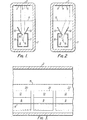
- Figures 1 and 2 illustrate cross-sectional views of a display arrangement in accordance with the present invention
- Figure 3 is a longitudinal section view.
- the display arrangement consists of a long tubular glass envelope 1 of approximately rectangular cross-section, a portion of which constitutes a fluorescent screen 2 and carries three longitudinal stripes 3, 4 and 5 of red, green and blue phosphor respectively.
- the envelope is sealed at both ends (not shown) and is evacuated.to a high level of vacuum.
- a single elongate cathode 6 is positioned towards the end of the rectangular section which is away from the screen 2, and on either side of the cathode 6 is a respective field electrode 7 and 8.
- the two electrodes together with the cathode 6 constitute an electron gun 9 which is arranged to produce a flood beam of electrons, the width of which is determined primarily by the opening 10 between the mouths of the two electrodes 7 and 8.
- a mesh electrode 11 is positioned between the electron gun and the screen 2.
- emission of electrons from the electron gun 9 can be controlled by the potentials applied to the field grids 7 and 8. By controlling the angle at which the electron beam energes, it can be caused to strike just one of the three stripes 3, 4 and 5 so that a red, green or blue patch of light can be selected at will.
- Figure I shows the trajectory of the electron flood beam when no lateral.deflection is applied to it so that it strikes the green stripe 4 and produces a correspondingly coloured patch of intense illumination.
- typical voltages are as follows. A very high potential is applied to the inner surface of the screen 2 and is typically about +7KV. The mesh electrode is held at +lOV and both field electrodes 7 and 8 are held at the same potential of +10V. All potentials are with respect to the nominal earth potential of the cathode 6.
- both field electrodes 7 and 8 are at the same potential, the electrons which are emitted from the cathode 6 experience a net positive electrostatic field, and are accelerated towards the mesh electrode 11.
- the width or spread of the flood beam in a direction transverse to the axis of the cathode is dictated by the width of the slotted opening 10, and that the flood beam electron continues to diverge in an almost linear manner until it reaches the mesh electrode 11 which is held at +10V.
- the extensions 12, 13 of the field electrodes 7 and 8 assist in controlling the profile of the flood beam as it leaves the electron gun.
- the electrons reach the mesh electrode 11 they are greatly influenced by the very high potential on the screen and are accelerated in a very rapid manner so that they strike the screen with high energy.
- the brightness of the display is determined by pulse width modulating the potential on the field electrodes, i.e. controlling the duration of the pulses applied to it.
- the cathode is a directly heated filament, that is to say its temperature is raised to that at which copious emission of electrons takes place by passing an electric current through it.
- the resistance of the filament is chosen so as to provide the required temperature rise.
- the electron beam is contained within the electron gun by applying a potential of -2V to the field electrodes 7 and 8 with respect to the cathode 6.
- the pulse repetition rate of the pulses applied to the field electrodes should be well above the flicker threshold of the eye, so that an observer sees a continuously present display.
- the red phosphor stripe 3 can be illuminated.
- the device as a whole can be turned on and off by applying a suitably negative potential to the mesh electrode 11, but this is not preferred if the mesh electrode is common to a plurality of electron guns which are to be operated independently of each other.
- FIG. 3 a longitudinal view of the display device is shown and it will be seen that a plurality of electron guns 20, 21 and 22 are mounted within the common elongate envelope along which the single continuous cathode 6 passes.
- Each electron gun consists simply of a respective pair of field electrodes in combination with the cathode, but in Figure 3 only the field electrodes 8 are visible.
- common potentials to the field mesh 11 and to the fluorescent screen 2
- the field electrodes constitute the entire electron gun in combination with a filamentry cathode but they can nevertheless produce a flood beam of electrons of controlled intensity and beam width.
- the angle at which the electron beam emerges from the gun can be finely controlled entirely by adjusting the relative potentials on the two field electrodes. Once the potentials have been adjusted, it is merely necessary to apply one of the three predetermined sets of potential values to the field electrodes 7 and 10 to produce a visible display of the required colour.
- a large number of separate electron guns can be mounted in a single tubular envelope 1, and a large number of tubular envelopes can be mounted side by side to produce a large two-dimensional display area with extremely good optical resolution, and excellent control over the colour of the separate pixels in the display.
Landscapes
- Physics & Mathematics (AREA)
- General Physics & Mathematics (AREA)
- Engineering & Computer Science (AREA)
- Theoretical Computer Science (AREA)
- Cathode-Ray Tubes And Fluorescent Screens For Display (AREA)
- Discharge Lamps And Accessories Thereof (AREA)
Applications Claiming Priority (2)
| Application Number | Priority Date | Filing Date | Title |
|---|---|---|---|
| GB08321146A GB2144575B (en) | 1983-08-05 | 1983-08-05 | Cathedolumanescent display arrangements |
| GB8321146 | 1983-08-05 |
Publications (2)
| Publication Number | Publication Date |
|---|---|
| EP0133360A2 true EP0133360A2 (de) | 1985-02-20 |
| EP0133360A3 EP0133360A3 (de) | 1989-04-26 |
Family
ID=10546874
Family Applications (1)
| Application Number | Title | Priority Date | Filing Date |
|---|---|---|---|
| EP84305131A Ceased EP0133360A3 (de) | 1983-08-05 | 1984-07-27 | Anzeigevorrichtung |
Country Status (4)
| Country | Link |
|---|---|
| US (1) | US4695765A (de) |
| EP (1) | EP0133360A3 (de) |
| JP (1) | JPS60100360A (de) |
| GB (1) | GB2144575B (de) |
Families Citing this family (5)
| Publication number | Priority date | Publication date | Assignee | Title |
|---|---|---|---|---|
| JPH01192072A (ja) * | 1988-01-27 | 1989-08-02 | Nec Home Electron Ltd | 電子装置内のフロッピーディスク駆動ユニット制御回路検査装置 |
| EP0526663A4 (en) * | 1991-02-27 | 1993-09-22 | Seiko Epson Corporation | Light projecting device |
| WO1992016012A1 (fr) * | 1991-03-01 | 1992-09-17 | Seiko Epson Corporation | Dispositif projecteur de lumiere |
| DE69218756T2 (de) * | 1991-09-26 | 1997-11-20 | Seiko Epson Corp | Belichtungsvorrichtung und Bild-lesevorrichtung. |
| CA2100052C (en) * | 1993-06-29 | 2005-02-15 | Humberto Takashi Kadooka | Semiconductor polymeric compound based on lampblack,polymeric semiconductor body, and methods of making the semiconductor polymeric compound and the polymeric semiconductor body |
Family Cites Families (11)
| Publication number | Priority date | Publication date | Assignee | Title |
|---|---|---|---|---|
| GB434868A (en) * | 1933-03-06 | 1935-09-06 | Fernseh Ag | Cathode-ray tubes for the production of pictures in natural colours, particularly for television and like systems |
| NL89130C (de) * | 1940-07-23 | |||
| US2623190A (en) * | 1950-02-13 | 1952-12-23 | Solo S Roth | Color television system |
| GB728053A (en) * | 1951-01-20 | 1955-04-13 | Standard Telephones Cables Ltd | Voltage indicator tube with two sensitivity ranges |
| NL172945B (nl) * | 1951-10-06 | Rhone Poulenc Ind | Verbetering van de werkwijze voor het stabiliseren en consolideren van grond bevattende samenstellingen. | |
| BE519456A (de) * | 1952-04-26 | |||
| GB882866A (en) * | 1957-11-27 | 1961-11-22 | Mullard Ltd | Improvements in or relating to cathode-ray devices |
| US3376447A (en) * | 1963-12-16 | 1968-04-02 | Philips Corp | Cathode-ray image scanning tube using low-velocity electron beam with electrostatic deflection and anamorphotic lens for improved focussing |
| DE1240592B (de) * | 1964-09-22 | 1967-05-18 | Standard Elektrik Lorenz Ag | Anzeigeroehre mit mehreren Ablenkelektroden, an die getrennte Anzeigespannungen gelegt werden |
| GB2031220B (en) * | 1978-10-04 | 1983-01-06 | English Electric Valve Co Ltd | Evacuated display tubes |
| JPS55121262A (en) * | 1979-03-13 | 1980-09-18 | Seiko Epson Corp | Fluorescent display unit |
-
1983
- 1983-08-05 GB GB08321146A patent/GB2144575B/en not_active Expired
-
1984
- 1984-07-27 EP EP84305131A patent/EP0133360A3/de not_active Ceased
- 1984-08-02 US US06/637,036 patent/US4695765A/en not_active Expired - Fee Related
- 1984-08-06 JP JP59164729A patent/JPS60100360A/ja active Pending
Also Published As
| Publication number | Publication date |
|---|---|
| GB2144575A (en) | 1985-03-06 |
| GB8321146D0 (en) | 1983-09-07 |
| US4695765A (en) | 1987-09-22 |
| GB2144575B (en) | 1988-04-20 |
| JPS60100360A (ja) | 1985-06-04 |
| EP0133360A3 (de) | 1989-04-26 |
Similar Documents
| Publication | Publication Date | Title |
|---|---|---|
| US4023063A (en) | Color tube having channel electron multiplier and screen pattern of concentric areas luminescent in different colors | |
| KR920006174B1 (ko) | 화상표시장치 | |
| DE3103293A1 (de) | Vakuumfluorezenzanzeigematrix und verfahren zu ihrem betrieb | |
| KR100221109B1 (ko) | 이미지 디스플레이 장치 | |
| US4243986A (en) | Display arrangements | |
| KR0140536B1 (ko) | 감소된 수의 애드레싱 회로를 갖는 마이크로돗트 형광 스크린과 상기 스크린의 애드레싱 방법 | |
| US4695765A (en) | Display arrangements | |
| US4387322A (en) | Display arrangements | |
| DE7730946U1 (de) | Vakuumfluoreszenz-darstellungsvorrichtung | |
| US4695764A (en) | Display arrangements | |
| US4598233A (en) | Color display tube and device having such a tube | |
| EP0009962B1 (de) | Anzeigevorrichtungen | |
| US5949395A (en) | Flat-panel matrix-type light emissive display | |
| EP0101195B1 (de) | Anzeigevorrichtung | |
| DE3011295C2 (de) | Anzeigevorrichtung | |
| US2907909A (en) | Light source | |
| US4193014A (en) | Display arrangements | |
| US2755413A (en) | Gas filled projector tubes for television | |
| GB1569973A (en) | Display arrangements | |
| EP0238799B1 (de) | Luminanzeinstellungssystem für eine Kathodenstrahlröhre der Flachmatrixart | |
| US4810928A (en) | Cathode-ray tube for constituting large picture display apparatus | |
| KR920004145B1 (ko) | 격자형 화상표시장치 | |
| US3406310A (en) | Direct-viewing color display storage device | |
| RU2217839C2 (ru) | Катодолюминесцентный матричный экран | |
| GB2057751A (en) | Two color write-through direct- viewing storage tube |
Legal Events
| Date | Code | Title | Description |
|---|---|---|---|
| PUAI | Public reference made under article 153(3) epc to a published international application that has entered the european phase |
Free format text: ORIGINAL CODE: 0009012 |
|
| AK | Designated contracting states |
Designated state(s): AT BE CH DE FR IT LI LU NL SE |
|
| PUAL | Search report despatched |
Free format text: ORIGINAL CODE: 0009013 |
|
| AK | Designated contracting states |
Kind code of ref document: A3 Designated state(s): AT BE CH DE FR IT LI LU NL SE |
|
| 17P | Request for examination filed |
Effective date: 19890506 |
|
| 17Q | First examination report despatched |
Effective date: 19900201 |
|
| STAA | Information on the status of an ep patent application or granted ep patent |
Free format text: STATUS: THE APPLICATION HAS BEEN REFUSED |
|
| 18R | Application refused |
Effective date: 19900730 |
|
| RIN1 | Information on inventor provided before grant (corrected) |
Inventor name: NIXON, RALPH DESMOND |