EP0132672B1 - Impulsgenerator - Google Patents
Impulsgenerator Download PDFInfo
- Publication number
- EP0132672B1 EP0132672B1 EP84107981A EP84107981A EP0132672B1 EP 0132672 B1 EP0132672 B1 EP 0132672B1 EP 84107981 A EP84107981 A EP 84107981A EP 84107981 A EP84107981 A EP 84107981A EP 0132672 B1 EP0132672 B1 EP 0132672B1
- Authority
- EP
- European Patent Office
- Prior art keywords
- pinion
- spur gear
- contact spring
- disposed
- contact
- Prior art date
- Legal status (The legal status is an assumption and is not a legal conclusion. Google has not performed a legal analysis and makes no representation as to the accuracy of the status listed.)
- Expired
Links
- 239000011810 insulating material Substances 0.000 claims 3
- 230000000717 retained effect Effects 0.000 claims 1
- 230000005540 biological transmission Effects 0.000 description 4
- 239000004952 Polyamide Substances 0.000 description 1
- 238000005299 abrasion Methods 0.000 description 1
- 230000001419 dependent effect Effects 0.000 description 1
- 238000009434 installation Methods 0.000 description 1
- 239000004033 plastic Substances 0.000 description 1
- 229920003023 plastic Polymers 0.000 description 1
- 229920002647 polyamide Polymers 0.000 description 1
- 229920002635 polyurethane Polymers 0.000 description 1
- 239000004814 polyurethane Substances 0.000 description 1
Images

Classifications
-
- H—ELECTRICITY
- H01—ELECTRIC ELEMENTS
- H01H—ELECTRIC SWITCHES; RELAYS; SELECTORS; EMERGENCY PROTECTIVE DEVICES
- H01H19/00—Switches operated by an operating part which is rotatable about a longitudinal axis thereof and which is acted upon directly by a solid body external to the switch, e.g. by a hand
- H01H19/005—Electromechanical pulse generators
-
- H—ELECTRICITY
- H01—ELECTRIC ELEMENTS
- H01H—ELECTRIC SWITCHES; RELAYS; SELECTORS; EMERGENCY PROTECTIVE DEVICES
- H01H19/00—Switches operated by an operating part which is rotatable about a longitudinal axis thereof and which is acted upon directly by a solid body external to the switch, e.g. by a hand
- H01H19/005—Electromechanical pulse generators
- H01H2019/006—Electromechanical pulse generators being rotation direction sensitive, e.g. the generated pulse or code depends on the direction of rotation of the operating part
Definitions
- the present invention relates to a pulse generator according to the preamble of claim 1.
- Such a pulse generator is known from DE-A-3 136 598. Although simple in structure, its mode of operation is not well suited for various applications. It has already been proposed to use such pulse generators, among others. to be used for frequency tuning in digital, in particular microprocessor-controlled radio and television receivers which can be tuned over large frequency ranges.
- the object of the invention is therefore to provide a pulse generator of the type mentioned, with which a large number of pulses can be emitted in a short time. At the same time, however, it should be possible to implement individual pulses of high accuracy. In addition, the pulse generator should be able to be manufactured in a compact design.
- the pulse generator is by a second z. B. lid-like housing part 4 in particular tightly closable.
- the contact spring set 3 consists of a central contact spring 5 and two outer contact springs 6 and 7, all of which lie in one plane.
- One contact 8 of the middle contact spring 5 can contact 9 of contact spring 6 and the other contact 10 of middle contact spring 5 can contact 11 of contact spring 7.
- the teeth of a spur gear 13 are operatively connected to the projecting end edge 12 of the contact spring 5.
- the latter is in a positive connection with a pinion 14 with a lower number of teeth.
- the spur gear 13 and pinion 14 expediently form a structural unit and advantageously consist of an abrasion-resistant plastic such as e.g. a polyamide or polyurethane.
- With the pinion 14 meshes a drive gear 15 with a larger number of teeth than that of the pinion 14, which is arranged below the contact spring set 3 and parallel to the same plane.
- the drive gear 15 is rigidly connected to a drive shaft 16 or consists of a single component.
- the first housing part 1 is provided with a bearing bush 17 in which it is rotatably and axially immovable.
- the axial fixation preferably takes place through the inner wall 18 of the first housing part 1 and the spur gear 13.
- the axis of rotation 19 of the pinion 14 and the spur gear 13 is rotatably fixed at the ends 20 and 21 according to FIG. 2 in a bearing bush 22 or 23 of the first housing part 1 or the second housing part 4.
- the axis of rotation 19 can be designed as a hollow axis.
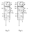
- a long bearing journal 24 is used on the first or second housing part 1 or 4 (FIG. 3) or a bearing journal 24 'is provided on the first housing part 1, which is shorter than the thickness of the spur gear 13 plus pinion 14, and on the second Housing part 4, a bearing pin 25 is provided (Fig. 4).
- the central contact spring 5 By rotating the drive shaft 16, the central contact spring 5 is deflected via the end edge 12, depending on the direction of rotation, to the left or right contact spring 6 or 7 via the transmission gear formed by the drive gear 15, pinion 14 and spur gear 13 through the teeth of the latter, so that the contacts 8 and 9 or 10 and 11 are briefly closed.
- a large number of pulses can be generated with small angles of rotation of the drive axis 16. Nevertheless, it is still possible to generate individual pulses with high accuracy.
- the structure is particularly compact due to the special arrangement of the drive gear 15 below the contact spring set 3 and parallel to the plane thereof.
Landscapes
- Saccharide Compounds (AREA)
- Transition And Organic Metals Composition Catalysts For Addition Polymerization (AREA)
- Mechanical Treatment Of Semiconductor (AREA)
- Gear Transmission (AREA)
- Connection Of Motors, Electrical Generators, Mechanical Devices, And The Like (AREA)
- Electromechanical Clocks (AREA)
- Ultra Sonic Daignosis Equipment (AREA)
- Electrotherapy Devices (AREA)
- Surgical Instruments (AREA)
- Rotary Switch, Piano Key Switch, And Lever Switch (AREA)
Description
- Die vorliegende Erfindung bezieht sich auf einen Impulsgenerator gemäss dem Oberbegriff des Anspruchs 1.
- Ein derartiger Impulsgenerator ist bekannt aus der DE-A-3 136 598. Dieser ist zwar einfach im Aufbau, aber in der Funktionsweise für verschiedene Anwendungsfälle nicht gut geeignet. So wurde bereits vorgeschlagen, solche Impulsgeneratoren u.a. zur Frequenzabstimmung in digitalen, insbesondere mikroprozessor-gesteuerten Rundfunk- und Fernsehempfängern zu verwenden, die über grosse Frequenzbereiche durchstimmbar sind.
- Aufgabe der Erfindung ist es daher, einen Impulsgenerator der genannten Art anzugeben, mit dem auch eine grosse Anzahl von Impulsen in kurzer Zeit abgegeben werden können. Gleichzeitig sollen jedoch Einzelimpulse hoher Genauigkeit realisierbar sein. Ausserdem soll der Impulsgenerator in kompakter Bauweise herstellbar sein.
- Gelöst wird diese Aufgabe durch die im Kennzeichen des Anspruchs 1 angegebenen Merkmale.
- Es ist zwar bei Impulsgeneratoren anderer Bauart und bei Dreh- oder Stufenschaltern bekannt, den Antrieb von Kontaktscheiben über ein Übersetzungsgetriebe vorzunehmen. Abgesehen davon, dass es sich dabei um vollkommen anders geartete Schalteinheiten handelt, ist keiner derselben die Anordnung des Antriebszahnrads unter den Schaltkontakten zu entnehmen. So sind in dem DE-U 1 913370 keinerlei Angaben über die Möglichkeit der speziellen Anordnung eines Übersetzungsgetriebes vorhanden, obwohl sich diese mit der Verringerung des Einbauraumes befasst, und bei den Getrieben gemäss der US-A 3 754 106 und der DE-A 2 217 540 ist das Antriebszahnrad jeweils ausserhalb der Kontaktbereiche angeordnet.
- Weitere vorteilhafte Einzelheiten der Erfindung sind in den abhängigen Ansprüchen angegeben und nachfolgend anhand der in der Zeichnung veranschaulichten Ausführungsbeispiele beschrieben.
- Dabei zeigen:
- Fig. 1 eine Ansicht eines erfindungsgemässen Impulsgenerators bei abgenommenem Verschlussteil und die
- Fig. 2 bis 4 je eine Seitenansicht mit schematischer Darstellung des Getriebes mit verschiedener Ausführung der Lagerungen.
- Mit 1 ist ein erstes beispielsweise kastenförmiges Gehäuseteil eines Impulsgenerators bezeichnet, an dem ein Isolierblock 2 mit einem Kontaktfedersatz 3 angebracht, z.B. an- oder eingesetzt oder in sonst geeigneter Weise befestigt ist. Der Impulsgenerator ist durch ein zweites z. B. deckelartiges Gehäuseteil 4 insbesondere dicht verschliessbar.
- Der Kontaktfedersatz 3 besteht aus einer mittleren Kontaktfeder 5 und zwei äusseren Kontaktfedern 6 und 7, die alle in einer Ebene liegen. Der eine Kontakt 8 der mittleren Kontaktfeder 5 kann den Kontakt 9 der Kontaktfeder 6 und der andere Kontakt 10 der mittleren Kontaktfeder 5 kann den Kontakt 11 der Kontaktfeder 7 kontaktieren.
- Mit der überstehenden Endkante 12 der Kontaktfeder 5 steht die Zahnung eines Stirnzahnrades 13 in Wirkverbindung. Letzteres ist mit einem Ritzel 14 geringerer Zähnezahl in kraftschlüssiger Verbindung. Zweckmässig bilden Stirnzahnrad 13 und Ritzel 14 eine bauliche Einheit und bestehen vorteilhaft aus einem abriebfesten Kunststoff wie z.B. einem Polyamid oder Polyurethan. Mit dem Ritzel 14 kämmt ein Antriebszahnrad 15 mit grösserer Zähnezahl als derjenigen des Ritzels 14, das unterhalb des Kontaktfedersatzes 3 und parallel zur Ebene desselben angeordnet ist. Das Antriebszahnrad 15 ist mit einer Antriebsachse 16 starr verbunden oder besteht mit dieser aus einem einzigen Bauteil. Zur Lagerung der Antriebsachse 16 ist das erste Gehäuseteil 1 mit einer Lagerbuchse 17 versehen, in der sie drehbar und axial unverschiebbar gelagert ist. Vorzugsweise erfolgt die axiale Fixierung durch die Innenwand 18 des ersten Gehäuseteils 1 und das Stirnzahnrad 13.
- Die Drehachse 19 des Ritzels 14 und des Stirnzahnrads 13 ist an den Enden 20 und 21 gemäss Fig.2 2 in je einer Lagerbuchse 22 bzw. 23 des ersten Gehäuseteils 1 bzw. des zweiten Gehäuseteils 4 drehbar lagefixiert.
- Gemäss den in Fig. 3 und 4 gezeigten Ausführungsbeispielen kann die Drehachse 19 als Hohlachse ausgebildet sein. Zur Lagerung dient entweder ein langer Lagerzapfen 24 am ersten oder zweiten Gehäuseteil 1 bzw. 4 (Fig.3) oder am ersten Gehäuseteil 1 ist ein Lagerzapfen 24' vorgesehen, der kürzer ist als die Dicke des Stirnzahnrads 13 plus Ritzel 14, und am zweiten Gehäuseteil 4 ist ein Lagerzapfen 25 vorgesehen (Fig. 4).
- Durch Drehen der Antriebsachse 16 wird über das aus Antriebszahnrad 15, Ritzel 14 und Stirnzahnrad 13 gebildete Übersetzungsgetriebe durch die Zähne des letzteren die mittlere Kontaktfeder 5 über deren Endkante 12 je nach Drehrichtung zur linken oder rechten Kontaktfeder 6 bzw. 7 ausgelenkt, so dass die Kontakte 8 und 9 oder 10 und 11 jeweils kurzzeitig geschlossen werden. Es kann dabei bei kleinen Drehwinkeln der Antriebsachse 16 eine grosse Anzahl von Impulsen erzeugt werden. Trotzdem ist es noch möglich, mit hoher Genauigkeit Einzelimpulse zu erzeugen. Weiterhin ist der Aufbau durch die besondere Anordnung des Antriebszahnrads 15 unterhalb des Kontaktfedersatzes 3 und parallel zur Ebene desselben besonders kompakt.
Claims (4)
Priority Applications (1)
| Application Number | Priority Date | Filing Date | Title |
|---|---|---|---|
| AT84107981T ATE37755T1 (de) | 1983-07-21 | 1984-07-07 | Impulsgenerator. |
Applications Claiming Priority (2)
| Application Number | Priority Date | Filing Date | Title |
|---|---|---|---|
| DE19833326308 DE3326308A1 (de) | 1983-07-21 | 1983-07-21 | Impulsgenerator |
| DE3326308 | 1983-07-21 |
Publications (3)
| Publication Number | Publication Date |
|---|---|
| EP0132672A2 EP0132672A2 (de) | 1985-02-13 |
| EP0132672A3 EP0132672A3 (en) | 1985-07-24 |
| EP0132672B1 true EP0132672B1 (de) | 1988-10-05 |
Family
ID=6204552
Family Applications (1)
| Application Number | Title | Priority Date | Filing Date |
|---|---|---|---|
| EP84107981A Expired EP0132672B1 (de) | 1983-07-21 | 1984-07-07 | Impulsgenerator |
Country Status (6)
| Country | Link |
|---|---|
| EP (1) | EP0132672B1 (de) |
| JP (1) | JPS6049517A (de) |
| AT (1) | ATE37755T1 (de) |
| CA (1) | CA1246643A (de) |
| DE (2) | DE3326308A1 (de) |
| ES (1) | ES8707046A1 (de) |
Families Citing this family (2)
| Publication number | Priority date | Publication date | Assignee | Title |
|---|---|---|---|---|
| DE3721460A1 (de) * | 1987-06-30 | 1989-01-12 | Standard Elektrik Lorenz Ag | Impulsgenerator |
| JP4066037B2 (ja) * | 2000-02-24 | 2008-03-26 | 株式会社ヴァレオサーマルシステムズ | 操作パネルの回転スイッチ機構 |
Citations (1)
| Publication number | Priority date | Publication date | Assignee | Title |
|---|---|---|---|---|
| DE1913370U (de) * | 1964-12-21 | 1965-04-08 | Befa Bau Elektro Feinmech App | Selbsttaetiges tastgeraet des alarm- und notzeichens fuer seeschiffe. |
Family Cites Families (5)
| Publication number | Priority date | Publication date | Assignee | Title |
|---|---|---|---|---|
| US3754106A (en) * | 1972-04-03 | 1973-08-21 | Donald W Mac | Panel display switch |
| DE2217540C3 (de) * | 1972-04-12 | 1975-01-30 | Fritz 8523 Baiersdorf Hartmann | Mehrfachstufenschalter |
| JPS5313177A (en) * | 1976-07-21 | 1978-02-06 | Alps Electric Co Ltd | Rotary pulse switch |
| DE3136598A1 (de) * | 1981-09-15 | 1983-03-31 | Horn Hans Joachim | "impulsgenerator" |
| JPS59121721A (ja) * | 1982-12-28 | 1984-07-13 | ホシデン株式会社 | 回転スイツチ |
-
1983
- 1983-07-21 DE DE19833326308 patent/DE3326308A1/de not_active Withdrawn
-
1984
- 1984-07-07 EP EP84107981A patent/EP0132672B1/de not_active Expired
- 1984-07-07 DE DE8484107981T patent/DE3474483D1/de not_active Expired
- 1984-07-07 AT AT84107981T patent/ATE37755T1/de not_active IP Right Cessation
- 1984-07-19 CA CA000459216A patent/CA1246643A/en not_active Expired
- 1984-07-20 ES ES534476A patent/ES8707046A1/es not_active Expired
- 1984-07-20 JP JP59149739A patent/JPS6049517A/ja active Pending
Patent Citations (1)
| Publication number | Priority date | Publication date | Assignee | Title |
|---|---|---|---|---|
| DE1913370U (de) * | 1964-12-21 | 1965-04-08 | Befa Bau Elektro Feinmech App | Selbsttaetiges tastgeraet des alarm- und notzeichens fuer seeschiffe. |
Also Published As
| Publication number | Publication date |
|---|---|
| ES534476A0 (es) | 1987-07-01 |
| EP0132672A3 (en) | 1985-07-24 |
| ATE37755T1 (de) | 1988-10-15 |
| JPS6049517A (ja) | 1985-03-18 |
| DE3474483D1 (en) | 1988-11-10 |
| CA1246643A (en) | 1988-12-13 |
| ES8707046A1 (es) | 1987-07-01 |
| EP0132672A2 (de) | 1985-02-13 |
| DE3326308A1 (de) | 1985-01-31 |
Similar Documents
| Publication | Publication Date | Title |
|---|---|---|
| DE3625599A1 (de) | Drehbarer optischer codierer | |
| DE3336669C2 (de) | Spielfreies Zahnradgetriebe | |
| DE2714020A1 (de) | Zahnrad aus kunststoff und verfahren zu seiner herstellung | |
| DE69006413T2 (de) | Vorrichtung zum Auswuchten einer sich drehenden Masse, insbesondere für Schleifscheiben. | |
| DE3129648C2 (de) | Sicherungsvorrichtung gegen ungewolltes Abrollen eines Rolltores | |
| DE69628673T2 (de) | Betätigungseinrichtung für eine elektrische schaltvorrichtung | |
| DE9308424U1 (de) | Stufenwähler mit Mehrfach-Grobwähler für Stufenschalter | |
| DE4035011C2 (de) | Rastwerk, insbesondere für Stufenschalter | |
| EP0144708A2 (de) | Impulsgenerator | |
| EP0132672A2 (de) | Impulsgenerator | |
| EP0432349A2 (de) | Getriebe | |
| DE2830511A1 (de) | Schlagbohrmaschine mit zweigang-getriebe und einer einrichtung zum umschalten der getriebegaenge und zum umstellen von bohren auf schlagbohren | |
| DE2714021C2 (de) | Vorrichtung zum Abschalten der Drehbewegung einer angetriebenen Welle | |
| DE3000477A1 (de) | Wellen-kreuzgelenk, insbesondere fuer eine exzenter-schneckenpumpe | |
| DE3508767C2 (de) | ||
| DE19548609C2 (de) | Zahnradgetriebe | |
| EP0132671B1 (de) | Impulsgeber | |
| DE3325588C2 (de) | Schaltuhr mit einer sich drehenden Programmscheibe | |
| DE2618114A1 (de) | Vorrichtung zur anzeige der stellung von drehbaren mechanischen elementen | |
| DE2751045A1 (de) | Mechanisches zaehlwerk | |
| DE2732255C2 (de) | Nicht rückstellbares Zählwerk | |
| DE2231575C3 (de) | Wischvorrichtung für Scheiben an Kraftfahrzeugen | |
| DE8322373U1 (de) | Ein- oder mehrpolige Stromübertragungsvorrichtung, inbesondere für Kabeltrommeln | |
| DE102021202458A1 (de) | Modulator für ein Magnetgetriebe und Magnetgetriebe | |
| DE3105379A1 (de) | Untersetzungsgetriebe fuer ein schrittschaltwerk, vorzugsweise fuer laufbildkameras |
Legal Events
| Date | Code | Title | Description |
|---|---|---|---|
| PUAI | Public reference made under article 153(3) epc to a published international application that has entered the european phase |
Free format text: ORIGINAL CODE: 0009012 |
|
| AK | Designated contracting states |
Designated state(s): AT DE FR GB IT |
|
| PUAL | Search report despatched |
Free format text: ORIGINAL CODE: 0009013 |
|
| AK | Designated contracting states |
Designated state(s): AT DE FR GB IT |
|
| 17P | Request for examination filed |
Effective date: 19851023 |
|
| 17Q | First examination report despatched |
Effective date: 19870428 |
|
| RAP1 | Party data changed (applicant data changed or rights of an application transferred) |
Owner name: STANDARD ELEKTRIK LORENZ AKTIENGESELLSCHAFT Owner name: ALCATEL N.V. |
|
| RAP3 | Party data changed (applicant data changed or rights of an application transferred) |
Owner name: STANDARD ELEKTRIK LORENZ AKTIENGESELLSCHAFT Owner name: ALCATEL N.V. |
|
| ITF | It: translation for a ep patent filed | ||
| GRAA | (expected) grant |
Free format text: ORIGINAL CODE: 0009210 |
|
| AK | Designated contracting states |
Kind code of ref document: B1 Designated state(s): AT DE FR GB IT |
|
| REF | Corresponds to: |
Ref document number: 37755 Country of ref document: AT Date of ref document: 19881015 Kind code of ref document: T |
|
| GBT | Gb: translation of ep patent filed (gb section 77(6)(a)/1977) | ||
| REF | Corresponds to: |
Ref document number: 3474483 Country of ref document: DE Date of ref document: 19881110 |
|
| ET | Fr: translation filed | ||
| PLBE | No opposition filed within time limit |
Free format text: ORIGINAL CODE: 0009261 |
|
| STAA | Information on the status of an ep patent application or granted ep patent |
Free format text: STATUS: NO OPPOSITION FILED WITHIN TIME LIMIT |
|
| 26N | No opposition filed | ||
| ITTA | It: last paid annual fee | ||
| PGFP | Annual fee paid to national office [announced via postgrant information from national office to epo] |
Ref country code: DE Payment date: 19920916 Year of fee payment: 9 |
|
| PGFP | Annual fee paid to national office [announced via postgrant information from national office to epo] |
Ref country code: FR Payment date: 19930527 Year of fee payment: 10 |
|
| PGFP | Annual fee paid to national office [announced via postgrant information from national office to epo] |
Ref country code: GB Payment date: 19930625 Year of fee payment: 10 |
|
| PGFP | Annual fee paid to national office [announced via postgrant information from national office to epo] |
Ref country code: AT Payment date: 19930723 Year of fee payment: 10 |
|
| PG25 | Lapsed in a contracting state [announced via postgrant information from national office to epo] |
Ref country code: DE Effective date: 19940401 |
|
| PG25 | Lapsed in a contracting state [announced via postgrant information from national office to epo] |
Ref country code: GB Effective date: 19940707 Ref country code: AT Effective date: 19940707 |
|
| GBPC | Gb: european patent ceased through non-payment of renewal fee |
Effective date: 19940707 |
|
| PG25 | Lapsed in a contracting state [announced via postgrant information from national office to epo] |
Ref country code: FR Effective date: 19950331 |
|
| REG | Reference to a national code |
Ref country code: FR Ref legal event code: ST |