EP0132337A2 - Vorrichtung und Verfahren zur Verminderung des "Aliasing-Artefaktes" bei der sagittalen oder koronalen NMR-Bilderzeugung - Google Patents
Vorrichtung und Verfahren zur Verminderung des "Aliasing-Artefaktes" bei der sagittalen oder koronalen NMR-Bilderzeugung Download PDFInfo
- Publication number
- EP0132337A2 EP0132337A2 EP84304650A EP84304650A EP0132337A2 EP 0132337 A2 EP0132337 A2 EP 0132337A2 EP 84304650 A EP84304650 A EP 84304650A EP 84304650 A EP84304650 A EP 84304650A EP 0132337 A2 EP0132337 A2 EP 0132337A2
- Authority
- EP
- European Patent Office
- Prior art keywords
- nmr
- frequency
- region
- interest
- signal
- Prior art date
- Legal status (The legal status is an assumption and is not a legal conclusion. Google has not performed a legal analysis and makes no representation as to the accuracy of the status listed.)
- Withdrawn
Links
Images


Classifications
-
- G—PHYSICS
- G01—MEASURING; TESTING
- G01R—MEASURING ELECTRIC VARIABLES; MEASURING MAGNETIC VARIABLES
- G01R33/00—Arrangements or instruments for measuring magnetic variables
- G01R33/20—Arrangements or instruments for measuring magnetic variables involving magnetic resonance
- G01R33/44—Arrangements or instruments for measuring magnetic variables involving magnetic resonance using nuclear magnetic resonance [NMR]
- G01R33/48—NMR imaging systems
- G01R33/4818—MR characterised by data acquisition along a specific k-space trajectory or by the temporal order of k-space coverage, e.g. centric or segmented coverage of k-space
- G01R33/482—MR characterised by data acquisition along a specific k-space trajectory or by the temporal order of k-space coverage, e.g. centric or segmented coverage of k-space using a Cartesian trajectory
-
- G—PHYSICS
- G01—MEASURING; TESTING
- G01R—MEASURING ELECTRIC VARIABLES; MEASURING MAGNETIC VARIABLES
- G01R33/00—Arrangements or instruments for measuring magnetic variables
- G01R33/20—Arrangements or instruments for measuring magnetic variables involving magnetic resonance
- G01R33/44—Arrangements or instruments for measuring magnetic variables involving magnetic resonance using nuclear magnetic resonance [NMR]
- G01R33/48—NMR imaging systems
- G01R33/54—Signal processing systems, e.g. using pulse sequences ; Generation or control of pulse sequences; Operator console
- G01R33/56—Image enhancement or correction, e.g. subtraction or averaging techniques, e.g. improvement of signal-to-noise ratio and resolution
- G01R33/565—Correction of image distortions, e.g. due to magnetic field inhomogeneities
- G01R33/56545—Correction of image distortions, e.g. due to magnetic field inhomogeneities caused by finite or discrete sampling, e.g. Gibbs ringing, truncation artefacts, phase aliasing artefacts
-
- G—PHYSICS
- G01—MEASURING; TESTING
- G01R—MEASURING ELECTRIC VARIABLES; MEASURING MAGNETIC VARIABLES
- G01R33/00—Arrangements or instruments for measuring magnetic variables
- G01R33/20—Arrangements or instruments for measuring magnetic variables involving magnetic resonance
- G01R33/28—Details of apparatus provided for in groups G01R33/44 - G01R33/64
- G01R33/32—Excitation or detection systems, e.g. using radio frequency signals
- G01R33/36—Electrical details, e.g. matching or coupling of the coil to the receiver
- G01R33/3621—NMR receivers or demodulators, e.g. preamplifiers, means for frequency modulation of the MR signal using a digital down converter, means for analog to digital conversion [ADC] or for filtering or processing of the MR signal such as bandpass filtering, resampling, decimation or interpolation
Definitions
- This invention relates to apparatus and method for NMR (nuclear magnetic resonance) imaging wherein data representing the internal point-by-point distribution of selected molecular structures within an object under test are obtained using nuclear magnetic resonance phenomena. More particularly, this invention relates to digitized signal generation of NMR images with greatly reduced aliasing artifacts and is especially useful when imaging only a portion of a cross-sectional plane through an extended region of an object such as is typically desired for sagittal and/or coronal image planes through the human body.
- NMR imaging is based on the ability to induce and monitor resonance of the magnetic moment of selected nuclei in the presence of magnetic fields. By the use of position-variant magnetic fields, it is possible to measure both the location and concentration in small volumes of resonant nuclei and, thereby, to create a visual display image that reflects this distribution in living tissue (e.g., a human body) or in other internal structures of an object under examination. Hydrogen, because it is the most sensitive of the stable nuclei to NMR phenomena and because it is also the most abundant nucleus in the human body, is ideally suited for NMR imaging. NMR imaging is a non-invasive diagnostic technique having some general similarity to computed tomography scanning (e.g. utilizing x-ray radiation) albeit it is based upon an entirely different physical phenomenon.
- the envelope of the radio frequency NMR signal response elicited from a region of interest is generally detected to provide an audio frequency NMR response signal (e.g. the envelope of a spin echo response).
- This audio frequency NMR response signal is subsequently sampled at repetitive intervals to provide digitized electrical signals representing the instantaneous signal value at the sample instants.
- sampled values are also typically accumulated over repeated similar measurement cycles (e.g. so as to obtain an acceptable signal-to-noise ratio) and stored for subsequent NMR image reconstruction and display using a digital data signal processing apparatus.
- a digital Fourier transform technique e.g.
- a Fast Fourier Transform or the like is utilized to process the sampled signal values and to thus derive the magnitude of frequency components in the NMR response signal which are associated with different physical. or spatial locations within the region of interest. That is, because of the magnetic gradient fields employed in the generation and read out of the NMR signal response, the spatial locations of nutated nuclei which provide the NMR response signal are encoded in the different frequency components of the NMR response signal.
- the maximum frequency component in the derived frequency spectrum of the NMR signal effectively defines the maximum image size or the "field of view".
- an anti-aliasing electrical filter has been employed with a cut-off frequency f c equal to approximately one-half the signal sampling rate 2f c . That is, the sampling rate has been chosen heretofore in accordance with conventional practice as being substantially equal to the Nyquist frequency normally associated with the cut-off frequency of the low pass anti-aliasing filter.
- both the filter cut-off frequency and the sampling rate have in the past jointly acted to define a coextensive reconstruction field of view.
- Such higher frequency components can typically be expected with sagittal or coronal cross-sections through the human body. This is due, for example, to the fact that a complete sagittal or coronal plane through the human body usually extends well beyond the field of view to be imaged (on one or the other or both ends) -- thus making it probable that high frequency components of significant magnitude are included within the NMR response elicited from the selected coronal or sagittal plane. Thus serious aliasing problems can be expected to occur more frequently and more severely with coronal and sagittal section NMR images than with transaxial NMR images.
- the sampling rate is chosen to be at than (e.g. twice) the nominal Nyquist rate associated with the cut-off frequency of the low pass anti-aliasing filter.
- the NMR response signals used in the presently preferred exemplary embodiment are spin echos elicited by selectively exciting a first portion of the object with a 90° r.f. nutation pulse and thereafter selectively exciting a second portion of the object with a 180° r.f. nutation pulse so as to elicit a spin echo response from a region of interest defined by the common intersecting region of the first and second portions.
- the preferred exemplary embodiment also repetitively measures similar spin echo signals and accumulates the measured sampled values before using them in an NMR reconstruction step that preferably comprises a two-dimensional Fourier transformation of the thus measured and/or accumulated sampled signal values.
- an NMR reconstruction step that preferably comprises a two-dimensional Fourier transformation of the thus measured and/or accumulated sampled signal values.
- a magnetic gradient is applied along the long axis of the body during the NMR spin echo occurrence such that the real-time low pass analog signal filtering reduces aliasing along the long axis of the body where aliasing artifact is potentially most serious.
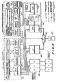
- the hard-wired apparatus employed in the presently preferred exemplary embodiment of this invention is similar to that employed and disclosed in the above-referenced copending patent applications from which FIGURES 1-2 have been substantially copied -- with the exception of the anti-aliasing filter 21 and its associated cut-off frequency control by the data acquisition and display computer 31 via the serial line interface and the control computer 20.
- the remaining functional differences in this equipment and in its operation which permit one to practice the presently described and claimed invention are achieved by reprogramming the data acquisition and display computer 31 so as to ensure that the sampling rate SR employed by the analog-to-digital converter 25 is substantially greater than the Nyquist frequency 2f c associated with the cut-off frequency f c of the anti-alias filter 21 (e.g. at least twice the Nyquist rate in the preferred embodiment).
- the data acquisition and display computer 31 must be provided with sufficient additional memory and appropriate programming to ensure that the now larger number of sampled data values are processed and stored.
- the present exemplary embodiment of this invention includes a static field magnetic coil 10 for generating a uniform static magnetic field Ho directed along its axis.
- the coil 10 is, in the exemplary embodiment, preferably large enough to receive a human body and is preferably surrounded by a cryogenic housing 12 filled with liquid helium or the like so as to permit the coil 10 to be superconducting.
- the static field is of approximately 3.5 KG thus making hydrogen nuclei exhibit NMR at approximately 15 MHz frequency.
- the X gradient coils, Y gradient coils and Z gradient coils shown in explosed perspective at FIGURE 1 are actually concentrically superimposed within the static field magnetic coil 10 and are preferably constructed so as to receive at least a portion of the human body therein.
- the RF transmit/receive coil is also of conventional design (as are the other coils shown in FIGURE 1) and is designed so as to cause the RF magnetic field to be perpendicular to the static magnetic field H O as will be appreciated by those in the art.
- a computerized control system 20 is in communication with the data acquisition and display computer 31 via a serial line link.
- This control system constitutes the NMR system control which controls the amplitude, timing and/or phasing of the necessary transmitted RF pulses, current drives to the magnetic gradient coils and RF detection processes required for NMR. It includes conventional data storage, data output/input and data entry components as appropriate to the requirements of a particular installation.
- the computer control system 20 typically also comprises plural data processors operating in parallel under control of a host data acquisition and display processor 31.
- the NMR system control 20 is of conventional design or as described in the earlier referenced copending applications and patents.
- an array processor e.g. CSPI Co. Model MAP 200
- CSPI Co. Model MAP 200 may be incorporated in the digital signal processing circuits to speed the required reconstruction digital data signal processing.
- the r.f. coil 22 is used for both transmitting and receiving r.f. energy to/from the object under test. It is selectively communicated with by either the r.f. transmitter 24 or the r.f. receiver 26 (and its associated anti-aliasing filter 21 and A/D converter 25) via an r.f. switch 28 which is, in turn, controlled via a control line by the NMR system control 20.
- This portion of the apparatus is used for selectively transmitting nutation pulses of r.f. energy into the object under test (said pulses having programmable amplitude, frequency, phase and duration so as to effect a desired nuclei nutation) and for selectively detecting NMR r.f. spin echo responses from the object under test during programmable listening periods.
- the r.f. signal generator, the r.f. transmitter 24, r.f. receiver and A/D converter 26 and r.f. switch 28 may be of the type described in greater detail in the earlier referenced issued patents and/or copending applications
- the anti-aliasing filter 21 may be an audio frequency low pass filter --,preferably having controllable cut-off frequency f c so that the sampling rate SR and filter cut-off f c can both be jointly varied, if desired, while still retaining relative values in accordance with this invention.
- a model 602 dual anti-alias filter commercially available from Precision Filters, Inc. is one suitable such filter.
- the filter cut-off frequency f c and the A/D sampling rate SR are both preferably controlled by the data acquisition computer 31 via the control computer 20 and a conventional serial to parallel digital interface.
- the magnetic gradient coil drivers 30 are controlled by the NMR system control 20 to selectively drive the X gradient coil, Y gradient coil and Z gradient coil with currents of programmable magnitude, duration, polarity, etcetera.
- TR and TE are the American College of Radiology standard symbols for the parameters which were formerly called b and a parameters in some of the earlier referenced related copending applications.
- TR is the repetition time of the measurement sequence and affects Tl contrast.
- TE is the time delay of the spin echo after the 90° nutation pulse and affects T2 contrast.
- FIGURES 3 and 4 are presented for a brief review of the preferred two-dimensional Fourier transformation reconstruction process described in above referenced related copending application Serial No. , -- as modified so as to permit NMR imaging of a sagittal plane (e.g. a cross-section parallel to the Y-Z plane shown in FIGURE 1).
- a sagittal plane e.g. a cross-section parallel to the Y-Z plane shown in FIGURE 1.
- an X gradient field is used to select a sagittal planar volume.
- the Z axis gradient is now employed during the spin echo read out so as to provide Z-axis phase encoding during the spin echo read out.
- the role of the X and Y axis gradients would be substituted, one for the other, from the depictions shown in FIGURE 3.
- a plurality of such sampled and NMR signal values are preferably accumulated over repetitive measurement cycles and then Fast Fourier Transformed to provide a digitized frequency spectrum representing line projections of the nutated spin densities.
- the discrete frequency components obtained by Fast Fourier Transformation represent line-projections of spin densities at different discrete corresponding spatial locations in a Z-axis dimension for a particular Y-axis phase encoded position. As depicted in FIGURES 3 and 4, this process is repeated for different Y-axis phase encoding positions.
- the result is an N by M array of frequency component values in frequency spectra obtained by Fast Fourier Transformation.
- all the depicted frequency component values in FIGURE 4 actually represent projections of spin density values.
- this second dimension of Fourier transformation will provide point-by-point spin density values at N x M corresponding locations on the Y-Z plane (or on a plane parallel thereto).
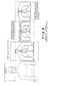
- FIGURE 5a when the NMR response signal emanates from a region of interest which is smaller than the reconstruction field of view, the region is correctly represented without aliasing artifact.
- the higher frequency components of the NMR analog signal can be expected to alias so as to appear as pseudo-lower frequency components in the reconstructed frequency spectra used to reconstruct the image.
- a portion of the image can be expected to "scroll" or "wrap around" the boundary of the field of view as depicted in FIGURE 5b.
- the overlapping portions of this alias artifact may either add or subtract from the true or correct image intensity at any given point depending upon the relative phases of the true NMR signal component at the corresponding frequency and the aliased frequency component.
- the actual frequency response curve of an anti-aliasing filter will be of the general type depicted at FIGURE 6 where frequency components above a given "cut-off" frequency f c are increasingly attenuated.
- the cut-off frequency of a filter is typically (although not necessarily) measured at the -3 decibel (dB) level of attenuation. Thereafter, the attenuation can increase at various rates depending upon the "sharpness" of the filter skirts (e.g. as depicted by solid skirt line 60 or, alternatively, a somewhat sharper dotted skirt line 62 at FIGURE 6).
- the sampling rate SR is chosen to be twice the filter cut-off frequency f c .
- the filter cut-off frequency f c is conventionally chosen to be one-half the sampling rate SR.
- signal components occurring at twice the cut-off frequency might be expected to be attenuated by, for example, -36 decibels (i.e. an output signal which is only 1.58% of the input signal level at this frequency).
- wrap around aliasing artifact can still be expected as depicted in FIGURE 7a even though the wrapped around or aliased image values can be expected to gradually fade away as also depicted in FIGURE 7a. This fading of the aliased signal components progresses as the aliased components approach the center of the field of view because these locations correspond to progressively higher aliased frequencies which are, in turn, therefore ever more attenuated by the anti-aliasing filter.
- the sampling frequency SR is substantially greater than twice the filter cut-off frequency f c .
- coronal imaging of the heart and lungs can involve interfering NMR response signals emanating from, for example, the head and liver. These unwanted NMR signals can actually be much stronger than the relatively low NMR response signals expected from the air-filled lungs.
- serious aliasing artifact can be expected with standard anti-aliasing filter and sampling rates. However, with a relatively higher sampling rate, the aliasing artifact can be eliminated in accordance with this invention.
- the preferred exemplary embodiment of this invention utilizes a two-dimensional Fourier transformation reconstruction technique with phase encoding in one dimension (e.g. the Y axis dimension as depicted in FIGURES 1, 3 and 4) there is no ready equivalent of the real time electrical low pass filter in this phase encoded dimension which might be used so as to relieve aliasing problems in this Y-dimension.
- the phase encoding dimension is preferably chosen in a direction which naturally has a limited signal producing region less than the reconstruction field of view.
- the limited body thickness (front to back) is chosen in the sagittal case for the phase encoding axis and the limited body width (left to right) of the body is used for phase encoding in the case of coronal imaging.
- the r.f. pickup coil is designed to have a very limited region of sensitivity, then this may permit the phase encoding to be done along the long axis (e.g. Z axis in the exemplary embodiment) of the body.
- the long body axis e.g. the Z axis
- the real time NMR spin echo response signal for which the real time analog electrical anti-aliasing filter can be utilized to limit the effective field of view in accordance with this invention.
- a very wide reconstructed field of view image which shows the entire region of interest and the limited sensitivity region of the r.f. pickup coil provides protection against aliasing (i.e., the coil limits the frequency range of signals detected from along this dimension) at the cost of storing and processing much more data than the present invention.
- aliasing i.e., the coil limits the frequency range of signals detected from along this dimension
- the neck and/or abdomen can alias and therefore interfere with the desired chest region image.
- the aliasing artifact can be significantly reduced.
- any frequency higher than one-half the increased sampling rate e.g. higher than 2f c
- the anti-aliasing filter provides considerably more relative attenuation such that these still aliased but now much higher frequency components are reduced in magnitude -- even below detectability.
- the sharper the filter skirts the less one may have to increase the sampling rate so as to avoid significant aliasing artifact.
- the sampling rate will still be chosen to be substantially higher than the natural Nyquist frequency (e.g. substantially higher than 2f c ) such that the cut-off frequency of the anti-aliasing filter and its attenuation characteristics effectively define the displayed field of view -rather than letting the sampling rate define not only the reconstruction field of view used in the reconstruction signal processing, but also the effective visible or displayed field of view.
- a sampling rate of 2.4 f c is sufficient to produce images with no detectable aliasing.
- the relatively increased sampling rates employed with this invention means that provisions must be made for storing and processing these additional sampled NMR signal values.
- these extra pixel values may not contain much real information due to the fact that the anti-aliasing filter has greatly attenuated the frequency components of the NMR signal corresponding to these outermost areas of the final image containing the extra pixels. Since this is the case, it may be desirable to simply program the computer to discard the reconstructed or computed pixel values and thus save on the data storage requirements for storing the computed pixel values to be used in displaying a final image.
- the extra sample points cannot themselves be discarded and must be used in the reconstruction process.
- One typical example of using this invention would be for a sagittal brain scan where the anti-aliasing filter is set to have a cut-off frequency of 7 KHz while the analog-to-digital converter is controlled to sample every 36 microseconds, corresponding to a sampling frequency of approximately 28 KHz (meaning that signal components up to a maximum frequency of approximately 14 KHz may be reliably reconstructed in accordance with the theorems of Nyquist).
- 256 samples will be taken in a 9.2 millisecond interval during which an NMR spin echo envelope is to be captured.
- the digitized Fourier transform of these samples will then provide a 256 point discrete frequency spectrum, the center 128 points of which constitute the desired image region and the outer 64 points on either side of the center portion containing information which is gradually fading away due to the ever increasing attenuation of the anti-aliasing filter for signal components corresponding to these outer locations. If the fading outer portions of the reconstructed image are not needed, they can be discarded as mentioned above so that the resulting computed image values will require only approximately one-half the data storage space which would otherwise be required.
- the anti-aliasing filter 21 may be an audio filter provided at the outputs of the r.f. demodulators and just ahead of the dual analog-to-digital converters 25.
- a model 602 dual anti-alias filter produced by Precision Filters Inc. is a suitable commercially available filter which has a remotely controlled cut-off frequency. This frequency cut-off control input and the A/D converter sample rate SR are each controlled by the data acquisition computer via the control computer and a serial to parallel digital interface in the preferred exemplary embodiment as earlier discussed.
Landscapes
- Physics & Mathematics (AREA)
- High Energy & Nuclear Physics (AREA)
- Condensed Matter Physics & Semiconductors (AREA)
- General Physics & Mathematics (AREA)
- Health & Medical Sciences (AREA)
- General Health & Medical Sciences (AREA)
- Nuclear Medicine, Radiotherapy & Molecular Imaging (AREA)
- Radiology & Medical Imaging (AREA)
- Engineering & Computer Science (AREA)
- Signal Processing (AREA)
- Magnetic Resonance Imaging Apparatus (AREA)
Applications Claiming Priority (2)
| Application Number | Priority Date | Filing Date | Title |
|---|---|---|---|
| US51595783A | 1983-07-21 | 1983-07-21 | |
| US515957 | 1983-07-21 |
Publications (2)
| Publication Number | Publication Date |
|---|---|
| EP0132337A2 true EP0132337A2 (de) | 1985-01-30 |
| EP0132337A3 EP0132337A3 (de) | 1986-12-30 |
Family
ID=24053516
Family Applications (1)
| Application Number | Title | Priority Date | Filing Date |
|---|---|---|---|
| EP84304650A Withdrawn EP0132337A3 (de) | 1983-07-21 | 1984-07-06 | Vorrichtung und Verfahren zur Verminderung des "Aliasing-Artefaktes" bei der sagittalen oder koronalen NMR-Bilderzeugung |
Country Status (2)
| Country | Link |
|---|---|
| EP (1) | EP0132337A3 (de) |
| JP (1) | JPS6078337A (de) |
Cited By (7)
| Publication number | Priority date | Publication date | Assignee | Title |
|---|---|---|---|---|
| NL8901353A (nl) * | 1988-05-31 | 1989-12-18 | Elscint Ltd | Vermindering van door afsluiting veroorzaakte artefacten. |
| EP0286677A4 (de) * | 1985-12-16 | 1990-06-28 | Yokogawa Medical Syst | Nmr-bildformungsverfahren. |
| EP0336479A3 (de) * | 1988-03-31 | 1991-01-02 | Philips Patentverwaltung GmbH | Kernresonanz-Spektrometer |
| WO1991015754A1 (en) * | 1990-04-04 | 1991-10-17 | Timothy Paul Leslie Roberts | Magnetic resonance experiment and apparatus |
| US5084675A (en) * | 1989-08-11 | 1992-01-28 | Siemens Aktiengesellschaft | Method for improving the signal-to-noise ratio in a nuclear magnetic resonance tomography apparatus |
| EP1477824A2 (de) | 2003-05-08 | 2004-11-17 | Kabushiki Kaisha Toshiba | Parallele magnetische Resonanzbildgebung |
| EP1837826A1 (de) * | 2006-03-20 | 2007-09-26 | Matsushita Electric Industrial Co., Ltd. | Bilderfassung unter Berücksichtigung von hochauflösender Nachinterpolation |
Families Citing this family (7)
| Publication number | Priority date | Publication date | Assignee | Title |
|---|---|---|---|---|
| JPS61286741A (ja) * | 1985-06-13 | 1986-12-17 | Yokogawa Medical Syst Ltd | Nmrイメ−ジング装置 |
| JPS62137045A (ja) * | 1985-12-11 | 1987-06-19 | 横河メディカルシステム株式会社 | Nmrイメ−ジング装置 |
| JPS62137553A (ja) * | 1985-12-11 | 1987-06-20 | Yokogawa Medical Syst Ltd | Nmrイメ−ジング装置 |
| JPS62217950A (ja) * | 1986-03-18 | 1987-09-25 | 横河メディカルシステム株式会社 | Nmrイメ−ジング装置 |
| JPS63160641A (ja) * | 1986-12-24 | 1988-07-04 | 株式会社日立メディコ | Mrイメ−ジング法 |
| US4885549A (en) * | 1988-11-30 | 1989-12-05 | General Electric Company | Method of phase and amplitude correction of NMR signals using a reference marker |
| US4992736A (en) * | 1989-08-04 | 1991-02-12 | General Electric Company | Radio frequency receiver for a NMR instrument |
Family Cites Families (5)
| Publication number | Priority date | Publication date | Assignee | Title |
|---|---|---|---|---|
| US4297637A (en) * | 1978-07-20 | 1981-10-27 | The Regents Of The University Of California | Method and apparatus for mapping lines of nuclear density within an object using nuclear magnetic resonance |
| US4319190A (en) * | 1980-03-06 | 1982-03-09 | Bell Telephone Laboratories, Incorporated | Nuclear magnetic resonance imaging in space and frequency coordinates |
| GB2091884B (en) * | 1981-01-26 | 1984-07-18 | Hinsaw Waldo Stephen | Investigation of samples by nmr techniques |
| DE3135335A1 (de) * | 1981-09-07 | 1983-08-18 | Siemens AG, 1000 Berlin und 8000 München | Kernspin-tomographie-verfahren |
| FI65862C (fi) * | 1982-10-11 | 1984-07-10 | Instrumentarium Oy | Nmr-avbildningsapparat |
-
1984
- 1984-07-06 EP EP84304650A patent/EP0132337A3/de not_active Withdrawn
- 1984-07-19 JP JP59150467A patent/JPS6078337A/ja active Pending
Cited By (16)
| Publication number | Priority date | Publication date | Assignee | Title |
|---|---|---|---|---|
| EP0286677A4 (de) * | 1985-12-16 | 1990-06-28 | Yokogawa Medical Syst | Nmr-bildformungsverfahren. |
| EP0336479A3 (de) * | 1988-03-31 | 1991-01-02 | Philips Patentverwaltung GmbH | Kernresonanz-Spektrometer |
| NL8901353A (nl) * | 1988-05-31 | 1989-12-18 | Elscint Ltd | Vermindering van door afsluiting veroorzaakte artefacten. |
| US5084675A (en) * | 1989-08-11 | 1992-01-28 | Siemens Aktiengesellschaft | Method for improving the signal-to-noise ratio in a nuclear magnetic resonance tomography apparatus |
| WO1991015754A1 (en) * | 1990-04-04 | 1991-10-17 | Timothy Paul Leslie Roberts | Magnetic resonance experiment and apparatus |
| US5296809A (en) * | 1990-04-04 | 1994-03-22 | Roberts Timothy P L | Magnetic resonance experiment and apparatus |
| US7102351B2 (en) | 2003-05-08 | 2006-09-05 | Kabushiki Kaisha Toshiba | Parallel imaging based on expanded unfolding technique |
| EP1477824A3 (de) * | 2003-05-08 | 2005-08-24 | Kabushiki Kaisha Toshiba | Parallele magnetische Resonanzbildgebung |
| EP1477824A2 (de) | 2003-05-08 | 2004-11-17 | Kabushiki Kaisha Toshiba | Parallele magnetische Resonanzbildgebung |
| US7205765B2 (en) | 2003-05-08 | 2007-04-17 | Kabushiki Kaisha Toshiba | Parallel imaging based on expanded unfolding technique |
| CN100339048C (zh) * | 2003-05-08 | 2007-09-26 | 株式会社东芝 | 基于扩大展开法的平行成像 |
| EP2541271A1 (de) * | 2003-05-08 | 2013-01-02 | Kabushiki Kaisha Toshiba | Parallele magnetische Resonanzbildgebung |
| EP1837826A1 (de) * | 2006-03-20 | 2007-09-26 | Matsushita Electric Industrial Co., Ltd. | Bilderfassung unter Berücksichtigung von hochauflösender Nachinterpolation |
| EP1998284A4 (de) * | 2006-03-20 | 2009-04-22 | Panasonic Corp | Videobildverarbeitungsvorrichtung, videobildverarbeitungsverfahren; programm und integrierte halbeiterschaltung |
| US8385665B2 (en) | 2006-03-20 | 2013-02-26 | Panasonic Corporation | Image processing apparatus, image processing method, program and semiconductor integrated circuit |
| US8682089B2 (en) | 2006-03-20 | 2014-03-25 | Panasonic Corporation | Image processing apparatus, image processing method, program and semiconductor integrated circuit |
Also Published As
| Publication number | Publication date |
|---|---|
| EP0132337A3 (de) | 1986-12-30 |
| JPS6078337A (ja) | 1985-05-04 |
Similar Documents
| Publication | Publication Date | Title |
|---|---|---|
| EP0132975B1 (de) | Verfahren und Vorrichtung zur rapiden NMR-Abbildung bei Anwendung von multi-dimensionalen Rekonstruktionstechniken | |
| US5122747A (en) | Spiral three-dimensional fourier transform NMR scan | |
| US4748410A (en) | Rapid NMR imaging system | |
| CN104685368B (zh) | 用于耐金属mr成像的方法和设备 | |
| US4698592A (en) | MRI of chemical shift spectra within limited inner volume | |
| JP5599893B2 (ja) | ナビゲータを使用するmrイメージング | |
| US8588889B2 (en) | Method and apparatus for breath-held MR data acquisition using interleaved acquisition | |
| US20080068014A1 (en) | Magnetic Resonance Imaging With Adjustment for Magnetic Resonance Decay | |
| JPH105191A (ja) | 三次元ディジタル減算磁気共鳴血管撮影法 | |
| EP0132337A2 (de) | Vorrichtung und Verfahren zur Verminderung des "Aliasing-Artefaktes" bei der sagittalen oder koronalen NMR-Bilderzeugung | |
| US7319324B2 (en) | MRI method and apparatus using PPA image reconstruction | |
| JPS63214247A (ja) | 像を発生する方法 | |
| JP4070268B2 (ja) | 画像の分解能を向上させる方法、投影画像の一部を拡大させる方法及び画像の分解能を向上させる装置 | |
| US6611701B2 (en) | Method and apparatus for fast breath-held 3D MR data acquisition using variable sampling | |
| CN107076818B (zh) | 零回波时间mr成像 | |
| US6046591A (en) | MRI system with fractional decimation of acquired data | |
| EP1745307A1 (de) | Mri mit trennung von fett- und wassersignal mittels radialer ssfp-sequenz | |
| JP2009106480A (ja) | 磁気共鳴イメージング装置 | |
| US5528144A (en) | Interleaved slab inversion for enhanced throughput in fluid attenuated inversion recovery imaging | |
| US6255820B1 (en) | Variable bandwidth MRI data collection | |
| JPH11276458A (ja) | 心拍時相画像を取得する方法及び装置 | |
| JP3735429B2 (ja) | Mriシステムを用いて一連の画像を形成する方法及び装置 | |
| JP2724830B2 (ja) | 核磁気共鳴信号を用い、対象物から高速度で影像情報を得る装置 | |
| JP2000350714A (ja) | 磁気共鳴イメージング検査装置 | |
| JP4202855B2 (ja) | 磁気共鳴イメージング装置 |
Legal Events
| Date | Code | Title | Description |
|---|---|---|---|
| PUAI | Public reference made under article 153(3) epc to a published international application that has entered the european phase |
Free format text: ORIGINAL CODE: 0009012 |
|
| AK | Designated contracting states |
Designated state(s): DE FR GB |
|
| PUAL | Search report despatched |
Free format text: ORIGINAL CODE: 0009013 |
|
| AK | Designated contracting states |
Kind code of ref document: A3 Designated state(s): DE FR GB |
|
| STAA | Information on the status of an ep patent application or granted ep patent |
Free format text: STATUS: THE APPLICATION IS DEEMED TO BE WITHDRAWN |
|
| 18D | Application deemed to be withdrawn |
Effective date: 19870701 |
|
| RIN1 | Information on inventor provided before grant (corrected) |
Inventor name: HOENNINGER, JOHN C., III Inventor name: CROOKS, LAWRENCE E. |