EP0132279B1 - Komposit-electromotorische vorrichtung und verwendung von sonnenenergie und ähnlichem - Google Patents
Komposit-electromotorische vorrichtung und verwendung von sonnenenergie und ähnlichem Download PDFInfo
- Publication number
- EP0132279B1 EP0132279B1 EP83903308A EP83903308A EP0132279B1 EP 0132279 B1 EP0132279 B1 EP 0132279B1 EP 83903308 A EP83903308 A EP 83903308A EP 83903308 A EP83903308 A EP 83903308A EP 0132279 B1 EP0132279 B1 EP 0132279B1
- Authority
- EP
- European Patent Office
- Prior art keywords
- thermocouple
- photovoltaic cell
- lens
- housing
- sunlight
- Prior art date
- Legal status (The legal status is an assumption and is not a legal conclusion. Google has not performed a legal analysis and makes no representation as to the accuracy of the status listed.)
- Expired - Lifetime
Links
Images


Classifications
-
- F—MECHANICAL ENGINEERING; LIGHTING; HEATING; WEAPONS; BLASTING
- F03—MACHINES OR ENGINES FOR LIQUIDS; WIND, SPRING, OR WEIGHT MOTORS; PRODUCING MECHANICAL POWER OR A REACTIVE PROPULSIVE THRUST, NOT OTHERWISE PROVIDED FOR
- F03G—SPRING, WEIGHT, INERTIA OR LIKE MOTORS; MECHANICAL-POWER PRODUCING DEVICES OR MECHANISMS, NOT OTHERWISE PROVIDED FOR OR USING ENERGY SOURCES NOT OTHERWISE PROVIDED FOR
- F03G6/00—Devices for producing mechanical power from solar energy
-
- F—MECHANICAL ENGINEERING; LIGHTING; HEATING; WEAPONS; BLASTING
- F03—MACHINES OR ENGINES FOR LIQUIDS; WIND, SPRING, OR WEIGHT MOTORS; PRODUCING MECHANICAL POWER OR A REACTIVE PROPULSIVE THRUST, NOT OTHERWISE PROVIDED FOR
- F03G—SPRING, WEIGHT, INERTIA OR LIKE MOTORS; MECHANICAL-POWER PRODUCING DEVICES OR MECHANISMS, NOT OTHERWISE PROVIDED FOR OR USING ENERGY SOURCES NOT OTHERWISE PROVIDED FOR
- F03G6/00—Devices for producing mechanical power from solar energy
- F03G6/001—Devices for producing mechanical power from solar energy having photovoltaic cells
-
- H—ELECTRICITY
- H10—SEMICONDUCTOR DEVICES; ELECTRIC SOLID-STATE DEVICES NOT OTHERWISE PROVIDED FOR
- H10F—INORGANIC SEMICONDUCTOR DEVICES SENSITIVE TO INFRARED RADIATION, LIGHT, ELECTROMAGNETIC RADIATION OF SHORTER WAVELENGTH OR CORPUSCULAR RADIATION
- H10F77/00—Constructional details of devices covered by this subclass
- H10F77/40—Optical elements or arrangements
- H10F77/42—Optical elements or arrangements directly associated or integrated with photovoltaic cells, e.g. light-reflecting means or light-concentrating means
- H10F77/488—Reflecting light-concentrating means, e.g. parabolic mirrors or concentrators using total internal reflection
-
- H—ELECTRICITY
- H10—SEMICONDUCTOR DEVICES; ELECTRIC SOLID-STATE DEVICES NOT OTHERWISE PROVIDED FOR
- H10N—ELECTRIC SOLID-STATE DEVICES NOT OTHERWISE PROVIDED FOR
- H10N10/00—Thermoelectric devices comprising a junction of dissimilar materials, i.e. devices exhibiting Seebeck or Peltier effects
-
- F—MECHANICAL ENGINEERING; LIGHTING; HEATING; WEAPONS; BLASTING
- F24—HEATING; RANGES; VENTILATING
- F24S—SOLAR HEAT COLLECTORS; SOLAR HEAT SYSTEMS
- F24S23/00—Arrangements for concentrating solar-rays for solar heat collectors
- F24S23/30—Arrangements for concentrating solar-rays for solar heat collectors with lenses
-
- F—MECHANICAL ENGINEERING; LIGHTING; HEATING; WEAPONS; BLASTING
- F24—HEATING; RANGES; VENTILATING
- F24S—SOLAR HEAT COLLECTORS; SOLAR HEAT SYSTEMS
- F24S50/00—Arrangements for controlling solar heat collectors
- F24S50/40—Arrangements for controlling solar heat collectors responsive to temperature
-
- Y—GENERAL TAGGING OF NEW TECHNOLOGICAL DEVELOPMENTS; GENERAL TAGGING OF CROSS-SECTIONAL TECHNOLOGIES SPANNING OVER SEVERAL SECTIONS OF THE IPC; TECHNICAL SUBJECTS COVERED BY FORMER USPC CROSS-REFERENCE ART COLLECTIONS [XRACs] AND DIGESTS
- Y02—TECHNOLOGIES OR APPLICATIONS FOR MITIGATION OR ADAPTATION AGAINST CLIMATE CHANGE
- Y02E—REDUCTION OF GREENHOUSE GAS [GHG] EMISSIONS, RELATED TO ENERGY GENERATION, TRANSMISSION OR DISTRIBUTION
- Y02E10/00—Energy generation through renewable energy sources
- Y02E10/40—Solar thermal energy, e.g. solar towers
- Y02E10/46—Conversion of thermal power into mechanical power, e.g. Rankine, Stirling or solar thermal engines
-
- Y—GENERAL TAGGING OF NEW TECHNOLOGICAL DEVELOPMENTS; GENERAL TAGGING OF CROSS-SECTIONAL TECHNOLOGIES SPANNING OVER SEVERAL SECTIONS OF THE IPC; TECHNICAL SUBJECTS COVERED BY FORMER USPC CROSS-REFERENCE ART COLLECTIONS [XRACs] AND DIGESTS
- Y02—TECHNOLOGIES OR APPLICATIONS FOR MITIGATION OR ADAPTATION AGAINST CLIMATE CHANGE
- Y02E—REDUCTION OF GREENHOUSE GAS [GHG] EMISSIONS, RELATED TO ENERGY GENERATION, TRANSMISSION OR DISTRIBUTION
- Y02E10/00—Energy generation through renewable energy sources
- Y02E10/50—Photovoltaic [PV] energy
- Y02E10/52—PV systems with concentrators
Definitions
- This invention relates to a solar energy converter for producing electricity.
- German patent Nos DE-A-2 412 908 (Schatta) and DE-A-2 460 075 (Schatta) describe apparatus for generating electricity using wind power.
- French patent No. 1 296 568 describes an apparatus for generating electricity for solar power using both photo and thermal energy.
- German patent No. DE A-2-604 175 (Thalheim) is another document which discusses the production of electricity from primarily wind power.
- electric generators consist of a single element system, e.g., in a hydroelectric generator system the flow of water is used to generate power.
- a thermoelectric steam power plant system there may be some problems involved in the generation of electricity. For example huge intermediate functional facilities, such as turbines and the like give rise to losses in the energy conversion.
- Wind power plant systems are disadvantageous in that there may be difficulties in stabilization due to the unstable, regional and/or climatic conditions which leads to inefficiency.
- This invention aims to provide a solar energy converter which requires less space, and involves fewer transfers of energy. It is also an aim of the invention to provide an apparatus which is suitable for portable use, is constructed as a single-body, or in the form of an array of individual converters.
- a solar energy converter comprising; at least one lens housed in a container for receiving sunlight and focusing the sunlight at a focal point of the lens, whereby the lens acts as a heat-collecting condenser; and at least one thermocouple(s) of which the high-temperature side(s) is/are positioned adjacent to the focal point of the lens and face(s) upwardly towards the lens, characterised in that a spacer is provided in the container for supporting the thermocouple and dividing the container into high and low temperature regions on respective sides of the thermocouple, the space between the lens and the thermocouple defining the high temperature region of the apparatus, and the thermocouple(s) acting so as to convert some of the sunlight into electrical energy; a photovoltaic cell disposed oppositely in the container with respect to the lens for receiving the sunlight diverging from the focal point and converting the sunlight into electric power, the space between the photovoltaic cell and the thermocouple(s) defining the low temperature region of the apparatus; a fan means
- thermocouple by means of the mutually cooperating effects of the lens, thermocouple, low and high temperature regions, converted currents, photovoltaic cell and fan means, an enhancement in the production of electrical energy from solar energy is achieved, without wasting hugh spaces or the need for complicated related-facilities.
- FIG 2a shows how a thermocouple 7 for use in embodiments of the invention can be switched between a battery 14 and a thermal indicator device 12 by a switching circuit 11.
- the thermocouple 7 can be coupled to the thermal indicator device 12 for indicating the temperature difference across the thermocouple 7.
- the thermocouple is coupled to the battery 14 therby contributing to the generation and storage of electric power.
- Figure 2b shows an alternative arrangement where one of a plurality of thermocouples 7 0 .7 n is permanently coupled to the therrmal indicator device 12 and another thermocouple 7, is permanently coupled to the battery 14.
- the battery equipment 14 includes charging, accumulating and discharging equipment for storing electrical energy in response to the electromotive force produced across the thermocouples 7 0 .7 " .
- thermocouples 7 0 ??7 n are selected and formed from materials which suit the ambient conditions and operating parameters.
- thermocouple-thermometers which are actually fit for high temperature measuring, are described in 'DENKI KOJI HIKKEI' (electric work handbook) edition supervised by HASUI, Takao, issued by SANSEIDO Co., Ltd., February 25, 1978, 3rd Edition.
- This edition includes tables indicating the E.M.F. generated by various thermocouples according to their composition and according to the temperature difference across them.
- the single thermocouple (thermometer) 7 has its high temperature side 7a directed to the incoming light.
- the switching circuit 11 is inserted in a serial circuit from the low temperature side 7b of the thermocouple 7 and is connected thereto by a lead wire passing through a waterproof plug attached to the back of the thermocouple at the cold junction.
- the switch 11 includes a transiently operable switch SW (that is the switch is on only when pushed, and OFF when the operator's hand is released) which, in one position triggers the relay X so as to make the relay X1 contact, and to make the relay x 2 break. In another position the relay X1 opens and the relay x 2 closes thereby switching on the thermal indicator 12.
- the switch SW may be operated via a solenoid key K, which may be controlled by a timer.
- the thermal indicator 12 is housed within a control centre room (instrument room). The measurement may be recorded if necessary.
- the battery equipment 14 is housed in an electricity room 13 (converter/transformer room etc.) and operates, to gain accumulation of the motivated electricity by virtue of the electromotive force provided by the thermocouple(s) 7.
- thermocouple-thermometers 7 0 , 7 1 (togethern) are set towards or at a heat source thermal substance 8.
- the circuit is to be connected to the thermal indicator 12, and for the purpose of providing electrical energy, the thermocouples 7 1 to 7 n are connected to the battery equipment 14.
- the lead wires 9 extend from their lead wire extraction hole (low-temperature part) side 7b.
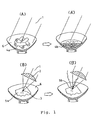
- FIG. 3 illustrates a vertical section through an embodiment of this invention.
- the embodiment comprises a mostly transparent and global vessel or container 20 (which is as far as possible constructed to be heat-resisting and fireproof, explosionproof, windproof, waterproof, and semi-airtight).
- the container 20 contains a convex lens 2 as a heat-collecting condenser, and openings 20a (which act as vents or capillary/channels and filters).
- a spacer 21 is positioned for dividing the container 20 into high and low-temperature regions 23, 24 respectively. The spacer 21 also serves to support the thermocouple 7.
- a photovoltaic cell 15, accepts sunlight etc. as diffused rays after being converged 1 a by the lens 2. The rays then diverge 1 before striking the surface of the photovoltaic cell 15a.
- a cooling fan 16, utilizing convention currents of warm air rising from the photovoltaic cell 15 acts for maintaining the low-temperature part side 7b of the thermocouple and for cooling the photovoltaic cell surface 15a.
- the fan 16 is associated with a magnet 17 and includes a coil 18. Relative rotation between the coil 18 and the magnet 17 (by virtue of rotation of the fan 16) generates some electricity which contributes to the overall conversion of solar energy to electrical energy.
- the generator, provided by the coil 18 and magnet 17 is described in more detail with reference to Figure 4.
- the fan 16 directs warm convective air down a venting route 16b and through lead wire path(s) 28a (see Figure 3).
- the solar energy converter of Figure 3 operates as follows: sunlight (etc.) 1 is collected and condensed by means of the lens 2 thereby adding to a light collecting effect resulting from the spherical and transparent container 20 itself.
- the condensed solar rays are focused at the lens focal point 3 positioned at the globe centre of the apparatus.
- the diffused rays of sunlight give rise to a temperature difference across the thermocouple 7.
- the thermocouple may comprise a disk 7 which is a compound of thermocouples.
- the high-temperature side of the thermocouple are positioned adjacent to the lens focal point 3.
- a temperature differential between the high-temperature part side 7a and the low-temperature part side (the circumference part side of the thermocouple elements disk) 7b gives rise to an electromotive force which contributes to the production of an electric current which in turn charges the battery 14.
- thermocouple's Peltier effect contributes to the efficiency of the apparatus.
- the Peltier effect arises from motivated electric current being charged on the thermocouple line element.
- the photovoltaic cell receives the sunlight 1 after divergence 1 b.
- the surface 15a may be in the form of photovoltaic elements shaped into a bowl, cup or other shaped surface e.g. the surface may be such as to have a focal point coincident with the focal point 3 in order to improve the efficiency of the photovoltaic cell.
- the use of convection by means of the cooling fan 16 enables heat removal to raise the photovoltaic action and effect of the photovoltaic cell 15a.
- the heat removal enhances the temperature differentiation effect at the thermocouple low-temperature part side 7b.
- warm air 16b heated by virture of the solar energy striking the photovoltaic cell 15 moves towards and into a neck vent 15b, thereby removing heat from the photovoltaic cell.
- the spacer 21 divides, together with the thermocouple elements disk 7, the vessel 20 into a high-temperature side 23 and low-temperature side 24.
- the spacer supports the thermocouple elements disk 7 and is available for supporting lead wires.
- the spacer 21 is supported by the vessel 20 (which may be semi-transparent to opeque at the bottom).
- the vessel 20 has pores which act as vents, capillary/channel and filters (outside opening and inside opening) 20a, 20b.
- the spacer 21 also has air adjusting openings with filters, (from warm to cool) 21 a and (from cool to warm) 21 b, and air adjusting valves, (from warm to cool) 21 c and (from cool to warm) 21 d, for promoting or aiding the fan's 16 rotation through convection etc. caused by temperature differentiation.
- the spacer 21 is designed to have a cool air current controlling rim 21e, high-temperature reflecting and holding wall surface 21f, cool vent protecting/controlling wall surface 22.
- FIG. 4 What is shown in Figure 4 is a detailed schematic and isometric drawing of an electrical generator of this embodiment of Figure 3, and includes a brief block diagram of the connecting devices, circuits, and the generator.
- the generator can be incorporated into the embodiments of Figures 5 and 6.
- the generator comprises a frame 27, which is positioned in the nect 25 of the vessel 20.
- a permanent magnet 17a with magnetic poles, N and S, 17b and 17c is provided in or on a surface of the frame inner wall 27a of the fan neck 25, a permanent magnet 17a with magnetic poles, N and S, 17b and 17c is provided.
- the ringshaped frame inner wall 27a encircles an element of coil 18.
- the drawing only schematically expresses the coil 18 with one turn although in actuality, a greater number of turns is provided.
- the coil 18 portion crosses the magnetic flux of the magnets 17.
- FIG. 4 An illustration of a multi-coil type construction is provided in the inset of Figure 4.
- This multi-coil is made of a coiled conductor, that is, a coiled coil.
- the axis of the coil 18 includes a conductive insulating tube which contains the current lead wire path 28b.
- This path is a general lead wire route and includes wires from the thermocouple elements disk 7 and the photovoltaic cell 15. Ventilation circuits may be constructed, according to necessities, enabling provision of automatic control of switching valves by air pressure.
- Generated electric current is fed to the battery 14 via lead wires 9 and slip rings 26a.
- the current then passes to circuits 29, 30, 31 for transforming and delivering the current to the supply.
- some of the ventilation or air current may be sent, via the route 28, drive remote and/or indirect facilities.
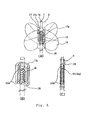
- FIG. 5 shows an illustration of another embodiment of this invention.
- a container or vessel 20 (heat resistant, fireproof, explosionproof, windproof and waterproof) is a transparent sealed vessel, has a convex lens 2a and a concave lens 2b formed in the faces of the vessel.
- the vessel 20 may be egg-shaped externally and spherical or global internally.
- the high-temperature part of the thermocouple 7a is positioned.
- a rotation axis passes through the low-temperature part 7b.
- a photo-accepter fan 19 is connected or interlocked with the permanent magnet 17a and rotates together with the magnet. Between the poles, 17a, b there is a coil 18.
- the thermocouple 7a operates.
- Diffused rays of sunlight after convergence 1 a, diverge 1 b and are accepted by the radiation photo-accepter fan rotor 19.
- the incidence of radiation on the fan rotor 19 causes rotation of the rotor which is enhanced by divergent radiation 1 from the concave lens 2b.
- the rotation of the photo-accepter fan rotor 19 drives the generator.
- the generator has the permanent magnet 17a which is connected to the fan rotor 19 and the coil 18 is set between the poles 17b, 17c of the permanent magnet.
- the photo-accepting rate of the fan rotor of the photovoltaic unit is higher owing to the transparent and sealed apparatus vessel 20 with convex and concave lens portions, 2a, 2b.
- the photo-accepter fan rotor 19 performs both functions as a photo-accepter and a fan and also functions as a radiator, and so this can be designed in single and simplified mode construction.
- thermocouple 7 high-temperature part side 7a and its low-temperature part side 7b In addition to the above, as for the use of this radiator photo-accepter fan rotor 19, its cooling and heat-removal function concerns holding and strengthening the temperature differentiation between the thermocouple 7 high-temperature part side 7a and its low-temperature part side 7b, and so, it is also effective for the conversion of solar energy to electric power.
- Fig. 6 shows another arrangement of a photo-accepter fan rotator/rotor.
- the generator is constructed as follows: (A) shows an assembly of the photo-accepter fan and generator 18; (B) is a detailed drawing of the fan rotor core; (C) is a representation how lead wires pass inside the insulating tube.
- the magnet is coupled to the fan rotor 19 so that when the rotor 19 rotates, relative motion exists between the coil 18 and the magnet 17. This relative motion results in the generation of electric power.
- Embodiments may be designed not only for a body in a fixed installation, but also for an attachment to a moving body.
Landscapes
- Engineering & Computer Science (AREA)
- Chemical & Material Sciences (AREA)
- Combustion & Propulsion (AREA)
- Mechanical Engineering (AREA)
- Sustainable Energy (AREA)
- Sustainable Development (AREA)
- Life Sciences & Earth Sciences (AREA)
- General Engineering & Computer Science (AREA)
- Photovoltaic Devices (AREA)
- Electromechanical Clocks (AREA)
- Golf Clubs (AREA)
- Hybrid Cells (AREA)
- Physical Or Chemical Processes And Apparatus (AREA)
- Radiation Pyrometers (AREA)
Claims (4)
Applications Claiming Priority (3)
| Application Number | Priority Date | Filing Date | Title |
|---|---|---|---|
| JP57229846A JPS59123277A (ja) | 1982-12-28 | 1982-12-28 | 太陽エネルギ−等を利用した複合起電装置 |
| JP229846/82 | 1982-12-28 | ||
| PCT/JP1983/000379 WO1984002584A1 (fr) | 1982-12-28 | 1983-10-26 | Appareil electromoteur composite utilisant l'energie solaire et analogue |
Publications (3)
| Publication Number | Publication Date |
|---|---|
| EP0132279A1 EP0132279A1 (de) | 1985-01-30 |
| EP0132279A4 EP0132279A4 (de) | 1985-06-26 |
| EP0132279B1 true EP0132279B1 (de) | 1994-06-22 |
Family
ID=16898596
Family Applications (1)
| Application Number | Title | Priority Date | Filing Date |
|---|---|---|---|
| EP83903308A Expired - Lifetime EP0132279B1 (de) | 1982-12-28 | 1983-10-26 | Komposit-electromotorische vorrichtung und verwendung von sonnenenergie und ähnlichem |
Country Status (7)
| Country | Link |
|---|---|
| US (1) | US4714797A (de) |
| EP (1) | EP0132279B1 (de) |
| JP (1) | JPS59123277A (de) |
| AT (1) | ATE107813T1 (de) |
| AU (1) | AU578232B2 (de) |
| DE (1) | DE3382754T2 (de) |
| WO (1) | WO1984002584A1 (de) |
Families Citing this family (12)
| Publication number | Priority date | Publication date | Assignee | Title |
|---|---|---|---|---|
| US4710588A (en) * | 1986-10-06 | 1987-12-01 | Hughes Aircraft Company | Combined photovoltaic-thermoelectric solar cell and solar cell array |
| DE3835279A1 (de) * | 1988-10-15 | 1990-04-19 | Willi Schickedanz | Energiequelle mit einem photovoltaischen element |
| FR2695462A1 (fr) * | 1992-09-10 | 1994-03-11 | Pulvar Richard | Générateur thermo-électrique. |
| US5408167A (en) * | 1994-02-08 | 1995-04-18 | Shea; Gerald J. | Solar energy magnetic resonance motor |
| RU2132589C1 (ru) * | 1998-02-20 | 1999-06-27 | Толстой Владимир Степанович | Способ получения электрического тока и источник тока на основе этого способа |
| DE19833180C2 (de) * | 1998-07-23 | 2003-01-02 | Hans K Seibold | Fertigungsverfahren für thermoelektrische Energiewandlerketten |
| US7326850B2 (en) * | 2002-11-22 | 2008-02-05 | Omnitek Partners Llc | Method and devices for generating energy from photovoltaics and temperature differentials |
| MX349759B (es) * | 2005-08-05 | 2017-08-11 | Retti Kahrl | Composicion, de multiples capas, quen recoge energia solar y metodo, nano-estructura c60 que recoge energia solar, dispositivo de acoplamiento inductivo; armazon de vehiculo; motor de hidrogeno de admision atmosferica; llanta rodante que genera energia electrica; y dispositivo que recoge energia mecanica. |
| DE102005054364A1 (de) * | 2005-11-15 | 2007-05-16 | Durlum Leuchten | Solarkollektor mit Kältemaschine |
| DE102008020815A1 (de) * | 2008-03-14 | 2009-10-15 | Ersol Solar Energy Ag | Photovoltaisches Solarmodul |
| ES2371582B1 (es) * | 2009-02-19 | 2012-12-13 | Juana Maria Aparicio Adarbe | Captador electrosolar por efecto termogalvánico. |
| JP2015050218A (ja) * | 2013-08-30 | 2015-03-16 | パナソニックIpマネジメント株式会社 | 太陽光発電装置 |
Family Cites Families (17)
| Publication number | Priority date | Publication date | Assignee | Title |
|---|---|---|---|---|
| US3053923A (en) * | 1959-07-31 | 1962-09-11 | Gen Dynamics Corp | Solar power source |
| US3293082A (en) * | 1959-09-22 | 1966-12-20 | Philips Corp | Thermo-electric device for measuring thermal radiation energy |
| FR1296568A (fr) * | 1961-01-30 | 1962-06-22 | R And R | Générateur solaire mixte photo-électrique et thermo-électrique pour l'alimentation du tube fluorescent et de la lampe solaire |
| US3977909A (en) * | 1974-03-18 | 1976-08-31 | Cremonese Otto A | Solar heat energy conversion system |
| DE2412908A1 (de) * | 1974-03-18 | 1975-10-02 | Martin Schatta | Wetter-kraftwerk (sonne, wind und wasser) |
| US4002499A (en) * | 1974-07-26 | 1977-01-11 | The United States Of America As Represented By The United States Energy Research And Development Administration | Radiant energy collector |
| DE2460075A1 (de) * | 1974-12-19 | 1976-07-01 | Martin Schatta | Wetter-kraftwerk |
| US4002031A (en) * | 1975-07-07 | 1977-01-11 | Varian Associates, Inc. | Solar energy converter with waste heat engine |
| US4147561A (en) * | 1975-09-25 | 1979-04-03 | Knight John R | Solar energy collector |
| US4002032A (en) * | 1975-11-28 | 1977-01-11 | Bash D Arle G | Solar heated device |
| DE2604175A1 (de) * | 1976-02-04 | 1977-08-11 | Klaus Dipl Ing Thalheim | Elektrischer energieerzeuger unter ausnutzung von sonne und wind |
| DE2713555A1 (de) * | 1976-03-30 | 1977-10-20 | Michael Gilbert Oramalu Iweka | Der gebrauch von pumpenturbinen in der direkten nutzung von natuerlicher energie |
| JPS53144296A (en) * | 1977-05-21 | 1978-12-15 | Tokyo Paipu Kk | Device for utilizing solar heat |
| IT1156794B (it) * | 1978-06-02 | 1987-02-04 | Cnen | Generatore elettrico solare a conversione diretta |
| US4276441A (en) * | 1980-02-15 | 1981-06-30 | Wilson International Incorporated | Thermoelectric generator and method of forming same |
| JPS57195391U (de) * | 1981-06-05 | 1982-12-10 | ||
| JPH05124433A (ja) * | 1991-10-31 | 1993-05-21 | Mazda Motor Corp | 自動車のロールブラインド装置 |
-
1982
- 1982-12-28 JP JP57229846A patent/JPS59123277A/ja active Pending
-
1983
- 1983-10-26 AU AU21225/83A patent/AU578232B2/en not_active Ceased
- 1983-10-26 DE DE3382754T patent/DE3382754T2/de not_active Expired - Fee Related
- 1983-10-26 AT AT83903308T patent/ATE107813T1/de not_active IP Right Cessation
- 1983-10-26 EP EP83903308A patent/EP0132279B1/de not_active Expired - Lifetime
- 1983-10-26 US US06/648,556 patent/US4714797A/en not_active Expired - Lifetime
- 1983-10-26 WO PCT/JP1983/000379 patent/WO1984002584A1/ja not_active Ceased
Also Published As
| Publication number | Publication date |
|---|---|
| AU2122583A (en) | 1984-07-17 |
| US4714797A (en) | 1987-12-22 |
| EP0132279A1 (de) | 1985-01-30 |
| ATE107813T1 (de) | 1994-07-15 |
| WO1984002584A1 (fr) | 1984-07-05 |
| EP0132279A4 (de) | 1985-06-26 |
| DE3382754T2 (de) | 1995-02-16 |
| JPS59123277A (ja) | 1984-07-17 |
| DE3382754D1 (de) | 1994-07-28 |
| AU578232B2 (en) | 1988-10-20 |
Similar Documents
| Publication | Publication Date | Title |
|---|---|---|
| EP0132279B1 (de) | Komposit-electromotorische vorrichtung und verwendung von sonnenenergie und ähnlichem | |
| US6313391B1 (en) | Solar power system using thermal storage and cascaded thermal electric converters | |
| US5047654A (en) | Solar powered electricity mine system | |
| US4251291A (en) | Thermoelectric generator with latent heat storage | |
| US4454865A (en) | Liquid metal solar power system | |
| JPS5997457A (ja) | 太陽エネルギ−利用装置 | |
| FR2415730A1 (fr) | Procede et dispositif pour produire de l'energie mecanique et/ou electrique, a partir de sources d'energie solaire et eolienne | |
| US20120180484A1 (en) | Heat storage system | |
| US20200036324A1 (en) | Methods of Producing Multiple Output Solar and Water Generator and Radiant Heater | |
| KR101771148B1 (ko) | 태양열 집열형 열전발전 모듈 및 이를 포함하는 시스템 | |
| US7185493B1 (en) | Solar energy power plant and method of producing electricity | |
| US9850883B1 (en) | Apparatus and method for generating electricity from integrated air flows and thermal energy | |
| JP2001153470A (ja) | 太陽熱発電システム | |
| CN102803723B (zh) | 用于太阳能收集和自然通风冷却的塔 | |
| US20100116266A1 (en) | Solar Energy Collecting Apparatus | |
| WO2015033249A1 (en) | Solar energy transfer and storage apparatus | |
| RU2013656C1 (ru) | Энергетическая установка | |
| JP2011196640A (ja) | ゼーベック素子と熱レンズ効果を用いた太陽輻射発電パネル | |
| KR850001560B1 (ko) | 집광 및 발전겸용 장치 | |
| RU2199704C2 (ru) | Гелиоэнергетическая установка | |
| JPS5661542A (en) | Apparatus for overall utilization of solar heat | |
| WO1996032586A1 (en) | Combined aeolian and solar energy converter | |
| CN102201762B (zh) | 户用太阳能温差发电站 | |
| JPS60242683A (ja) | 太陽熱電変換素子 | |
| RU96112554A (ru) | Солнечная энергетическая установка |
Legal Events
| Date | Code | Title | Description |
|---|---|---|---|
| PUAI | Public reference made under article 153(3) epc to a published international application that has entered the european phase |
Free format text: ORIGINAL CODE: 0009012 |
|
| AK | Designated contracting states |
Designated state(s): AT BE CH DE FR GB LI LU NL SE |
|
| 17P | Request for examination filed |
Effective date: 19841220 |
|
| 17Q | First examination report despatched |
Effective date: 19870317 |
|
| RAP1 | Party data changed (applicant data changed or rights of an application transferred) |
Owner name: NAGAI, TOKI |
|
| GRAA | (expected) grant |
Free format text: ORIGINAL CODE: 0009210 |
|
| AK | Designated contracting states |
Kind code of ref document: B1 Designated state(s): AT BE CH DE FR GB LI LU NL SE |
|
| PG25 | Lapsed in a contracting state [announced via postgrant information from national office to epo] |
Ref country code: NL Effective date: 19940622 Ref country code: BE Effective date: 19940622 Ref country code: AT Effective date: 19940622 |
|
| REF | Corresponds to: |
Ref document number: 107813 Country of ref document: AT Date of ref document: 19940715 Kind code of ref document: T |
|
| REF | Corresponds to: |
Ref document number: 3382754 Country of ref document: DE Date of ref document: 19940728 |
|
| PG25 | Lapsed in a contracting state [announced via postgrant information from national office to epo] |
Ref country code: SE Effective date: 19940922 |
|
| PG25 | Lapsed in a contracting state [announced via postgrant information from national office to epo] |
Ref country code: LU Free format text: LAPSE BECAUSE OF NON-PAYMENT OF DUE FEES Effective date: 19941031 |
|
| ET | Fr: translation filed | ||
| NLV1 | Nl: lapsed or annulled due to failure to fulfill the requirements of art. 29p and 29m of the patents act | ||
| PLBE | No opposition filed within time limit |
Free format text: ORIGINAL CODE: 0009261 |
|
| STAA | Information on the status of an ep patent application or granted ep patent |
Free format text: STATUS: NO OPPOSITION FILED WITHIN TIME LIMIT |
|
| 26N | No opposition filed | ||
| PGFP | Annual fee paid to national office [announced via postgrant information from national office to epo] |
Ref country code: GB Payment date: 20011024 Year of fee payment: 19 |
|
| PGFP | Annual fee paid to national office [announced via postgrant information from national office to epo] |
Ref country code: FR Payment date: 20011025 Year of fee payment: 19 |
|
| PGFP | Annual fee paid to national office [announced via postgrant information from national office to epo] |
Ref country code: DE Payment date: 20011112 Year of fee payment: 19 |
|
| PGFP | Annual fee paid to national office [announced via postgrant information from national office to epo] |
Ref country code: CH Payment date: 20011114 Year of fee payment: 19 |
|
| REG | Reference to a national code |
Ref country code: GB Ref legal event code: IF02 |
|
| PG25 | Lapsed in a contracting state [announced via postgrant information from national office to epo] |
Ref country code: GB Free format text: LAPSE BECAUSE OF NON-PAYMENT OF DUE FEES Effective date: 20021026 |
|
| PG25 | Lapsed in a contracting state [announced via postgrant information from national office to epo] |
Ref country code: LI Free format text: LAPSE BECAUSE OF NON-PAYMENT OF DUE FEES Effective date: 20021031 Ref country code: CH Free format text: LAPSE BECAUSE OF NON-PAYMENT OF DUE FEES Effective date: 20021031 |
|
| PG25 | Lapsed in a contracting state [announced via postgrant information from national office to epo] |
Ref country code: DE Free format text: LAPSE BECAUSE OF NON-PAYMENT OF DUE FEES Effective date: 20030501 |
|
| REG | Reference to a national code |
Ref country code: CH Ref legal event code: PL |
|
| GBPC | Gb: european patent ceased through non-payment of renewal fee | ||
| PG25 | Lapsed in a contracting state [announced via postgrant information from national office to epo] |
Ref country code: FR Free format text: LAPSE BECAUSE OF NON-PAYMENT OF DUE FEES Effective date: 20030630 |
|
| REG | Reference to a national code |
Ref country code: FR Ref legal event code: ST |
|
| APAH | Appeal reference modified |
Free format text: ORIGINAL CODE: EPIDOSCREFNO |