EP0132086A2 - Verfahren und Anordnung zur Fehlerkorrektur in digitalen Daten - Google Patents
Verfahren und Anordnung zur Fehlerkorrektur in digitalen Daten Download PDFInfo
- Publication number
- EP0132086A2 EP0132086A2 EP84304601A EP84304601A EP0132086A2 EP 0132086 A2 EP0132086 A2 EP 0132086A2 EP 84304601 A EP84304601 A EP 84304601A EP 84304601 A EP84304601 A EP 84304601A EP 0132086 A2 EP0132086 A2 EP 0132086A2
- Authority
- EP
- European Patent Office
- Prior art keywords
- words
- data
- check
- error
- blocks
- Prior art date
- Legal status (The legal status is an assumption and is not a legal conclusion. Google has not performed a legal analysis and makes no representation as to the accuracy of the status listed.)
- Withdrawn
Links
Images


Classifications
-
- H—ELECTRICITY
- H04—ELECTRIC COMMUNICATION TECHNIQUE
- H04N—PICTORIAL COMMUNICATION, e.g. TELEVISION
- H04N5/00—Details of television systems
- H04N5/76—Television signal recording
- H04N5/91—Television signal processing therefor
- H04N5/93—Regeneration of the television signal or of selected parts thereof
- H04N5/94—Signal drop-out compensation
- H04N5/945—Signal drop-out compensation for signals recorded by pulse code modulation
-
- G—PHYSICS
- G11—INFORMATION STORAGE
- G11B—INFORMATION STORAGE BASED ON RELATIVE MOVEMENT BETWEEN RECORD CARRIER AND TRANSDUCER
- G11B20/00—Signal processing not specific to the method of recording or reproducing; Circuits therefor
- G11B20/10—Digital recording or reproducing
- G11B20/18—Error detection or correction; Testing, e.g. of drop-outs
- G11B20/1806—Pulse code modulation systems for audio signals
- G11B20/1809—Pulse code modulation systems for audio signals by interleaving
Definitions
- This invention relates to methods of and apparatus for correcting errors in binary data, and particularly, but not exclusively, to methods of and apparatus for correcting errors in digital television signals after recording and reproduction.
- check words are additional to the data words, and therefore in a sense redundant, more sophisticated methods of generating the check words, which result in an improved error detection and correction capability without undue increase in the number of check words required are in use particularly for digital television signals where the amount of data involved means that even without the addition of redundant words, very high bit rates have to be used.
- Examples of more sophisticated methods which have been used for digital television signals are various so-called b-adjacent codes, of which the Reed-Solomon code is a particular example, and the Bose-Chaudhuri-Hocquenghem code.
- a common problem with prior methods of error detection and correction using check words is that if an error occurs in a check word, for example, during transmission or during recording and reproduction, this may mean that error detection and correction using that check word is impossible, or alternatively wrong error detection and correction may occur. In the case of a digital television signal either of these eventualities may result in serious deterioration of a reproduced television picture.
- Another problem is that while the use of such an error detection end correction method using check words may permit the detection and correction of up to several errors in the block of data words protected by those check words, the method does not provide adequate protection against a burst error involving a substantial sequence of data words and caused, for example, by a tape drop-out.
- a method of correcting errors in binary data comprising assembling the data into a plurality of data blocks, each said data block comprising a first plurality of data words and a second plurality of check words, each said check word being derived in dependence on all said data words in said data block and each other said check word in said data block, and further assembling said data blocks into an array consisting of a plurality of said data blocks and deriving first and second check blocks for each said array.
- apparatus for correcting errors in binary data comprising means for assembling the data into a plurality of data blocks, each said data block comprising a first plurality of data words and a second plurality of check words, each said check word being derived in dependence on all said data words in said data block and each other said check word in said data block, and means for further assembling said data blocks into an array consisting of a plurality of said data blocks and for deriving first and second check blocks for each said plurality of data blocks.
- FIG. 1 shows a coding format applied to a digital television signal.
- Each horizontal line scan of an incoming analog television signal has, as a preliminary, been sampled a predetermined number of times and each of the resulting samples has been pulse code modulation coded into an 8-bit date word.
- the part of the format shown in Figure 1 covers an array of m rows by n columns of data blocks where each data block consists, for example as shown in Figure 2, of sixty 8-bit data words plus six 8-bit horizontal check words corresponding to those data words.
- m is equal to eighteen and n is equal to thirty-six, where the first thirty-four of the thirty-six rows correspond to active samples and the final two rows consist of eighteen first and eighteen second vertical check blocks, which will be referred to in more detail below.
- Each row contains three horizontal lines of video.
- Three arrays are required to make up one field of 306 lines. (3121 lines are contained in one field of a 625-line system, the difference of 6i lines being taken from inactive regions of the picture, that is blanking lines.)
- the particular system used in this example is a so-called 2:1:1 system applied to a component television signal in which the luminance component signal is sampled at 6.75 MHz and each colour difference component signal is sampled at 3.375 M-iz. This results in a total 720 active samples per horizontal scan line or 13.5 megawords/second.
- the final two rows of each m x n array consist of first and second vertical check blocks each of which comprises sixty-six 8-bit vertical check words.
- the vertical check words in the first vertical check block are generated by bit-by-bit exclusive-OR (that is, modulo-2) addition of the individual bits of the vertically aligned data words in the first n-2 rows of the m x n array.
- the vertical check words of the second vertical check block are derived from the same data words but form a b-adjacent code which is preferably a Reed-Solomon code.
- the first and second vertical check blocks are generated in a manner to be described in more detail below, preferably before the horizontal check words have been added to the data blocks of data words in the m x n arrays and before any necessary synchronizing words have been added.
- the method of coding outlined above and to be described in more detail below permits of various possibilities on decoding. This results from the fact that the six horizontal check words in each data block shown in Figure 2 permit the detection and correction of at least two error words in the data block. Moreover, the first and second vertical check words in the final two rows of each column permit, for example, the detection and correction of a single error word in that column or the detection of two error words in that column.
- interleaving Another previously proposed technique for improving error correction is interleaving, and that technique can also be used in the present error correction formats.
- the effect of interleaving is to spread errors, so that if a burst error occurs there is a greater probability of each of the individual word errors being corrected.
- Each of the data words W 0 to W 33 represents in pulse code modulated form a sample level of an analog television signal, the sample range having 256 steps, that is 2 8 .
- Associated with the block are two 8-bit check words K O and K 1 to provide error correction of one 8-bit date word, by identifying the position of the word in error and the magnitude of the error. This might be considered as providing two simultaneous equations which are solved to find the two unknowns.
- the two check words must each be derived in dependence on all the data words in the block, but in different ways, so as to ensure that they include independent information and hence the equations are soluble.
- a b-adjacent code is one way of obtaining this independence.
- the first check word K O is derived by the simple modulo-2 addition of all thirty-four data words. That is: where ⁇ represents modulo-2 addition, achieved by the circuit of Figure 9A.
- the second check word K 1 is derived using a primitive polynomial generator.
- the centre of the circle represents the 8-bit word 00000000.
- steps designated ⁇ 0 , ⁇ 1 , ⁇ 2 , . . ⁇ 254 representing all the different non-zero patterns of an 8-bit code.
- the effect of the polynomial generator which is conveniently formed as an 8-stage feedback shift register interconnected as shown in Figure 9B, is to step an input data word clockwise around the circle when the shift register is clocked once. Thus if an 8-bit data word is stored in the shift register, the word may be considered as having been multiplied by ⁇ 0 , that is by one.
- any input 8-bit combination other than 00000000 supplied to the shift register will cycle in a predetermined manner through all the other possible combinations before returning to the original combination.
- the advantages of this modification are that it avoids the need for reverse stepping, so a primitive polynomial generator of the same configuration as used in the coder can be used, and it requires only one delay store, rather than two first-in last-out stores.
- the above-described error correcting code will correct a single error without fail.
- the check words K O and K 1 will enable the magnitude and the position of the error to be determined.
- one of the syndromes So or S 1 will be zero and the other will be non-zero, thus indicating that the error is in one of the check words S 0 or S 1 and the data words W 0 to W 33 are error-free.
- the Hamming code will assume a single error and make a wrong correction.
- the check word C 0 is formed as a modulo-2 sum and the check word C 1 is formed using a primitive polynomial generator, but whereas the check words K 0 and K 1 of Figure 4 are both in effect related to the position 33 in the block, the check words C 0 and C 1 are in effect related to the position 35.
- the check words K 0 and K 1 of Figure 4 are derived in dependence on the data words up to and including the last data word W 33 in the position 33
- the check words C o and C 1 of Figure 6 are derived in dependence on the data words up to and including the last data word W 33 in the position 33 plus the check words C o and C 1 themselves in the positions 34 and 35.
- each of the check words C o and C 1 contains information concerning the other check word, so that in decoding, the check words C 0 and C 1 can be treated exactly as if they were data words, and if there is a single error the magnitude and position of the error can be determined even if the error is in one of the check words C 0 or C 1 .
- Equations (1) and (6) show how the check words K 0 and K 1 of Figure 4 could be derived from the data words W 0 to W 33 :
- Equations (11) and (12) can be re-written: and In matrix form this becomes The centre matrix is in fact a Vandemonde determinant, so it always has a real inverse, and equation (15) can be solved for C o and C 1 .
- Figure 7 shows in block schematic form a circuit for generating the check words C o and C 1 .
- the incoming data words W 0 to W 33 are supplied by way of an input 10 to first and second primitive polynomial generators 11 and 12 which derive the intermediate words K 0 and K 1 respectively, and also to a 2:1 selector 13.
- the intermediate word K 0 derived by the primitive polynomial generator 11 is supplied to a (512 x 8) PROM 14 and the intermediate word K 1 derived by the primitive polynomial generator 12 is supplied to a (512 x 8) PROM 15.
- the intermediate words K 0 and K 1 are supplied to the input terminals A 0 to A 7 of the PROMs 14 and 15 respectively and to the input terminals A 8 are supplied switching signals to cause the PROMs 14 and 15 to operate alternately to derive the check words C o and C l , which are supplied by way of an exclusive - OR circuit 16 to the 2:1 selector 13.
- the output of the 2:1 selector 13 is formed by the data words W 0 to W 33 with the associated check words C o and C l .
- both the incoming data words and the incoming check words are used, and in consequence the syndromes are derived directly. If there are no errors in the check words then both syndromes are zero. If both the syndromes are non-zero then the assumption is that there is a single error, and the magnitude and position of this error can be found by a Chien search. It may be, of course, that this Chien search reveals that the single error is in one of the check words, in which case the data words are simply passed as valid, with no correction being necessary. If one syndrome is zero and the other is non-zero, then there is more than one error. An improved method of decoding will be described below.
- Figure 8 indicates diagrammatically the sixty data words W 0 to W 59 (W K-1 ) of a data block, with which are associated the six horizontal check words.
- W K-1 the sixty data words
- the use of six horizontal check words with sixty data words gives a level of redundancy which has been used in several prior methods, but the number of data words could be different, with appropriate changes to the formats of Figures 1 and 2, so long as the number W K-1 lies within the range 1 to 249 inclusive.
- the data words with the six associated horizontal check words form a modified 3-error correcting Reed-Solomon code. It is not required to use the full 3-error correcting capability to correct errors within the data block and the associated horizontal check words, and this capability may be used in the first step of error correction on decoding merely to correct one or two errors in the data words and the associated check words.
- the check words K0 to K 5 can be generated from the data words W 0 to W K-1 using primitive polynomial generators as referred to above.
- the particular primitive polynomial generators required to generate the check words K O and K 1 are illustrated in block diagrammatic form in Figures 9A and 9B.
- each of the primitive polynomial generators comprises eight input terminals 20 each connected to one input of a respective exclusive-OR circuit 21, the output of which is connected to the input of a respective shift register stage 22, each having an output connected to a respective output terminal 23.
- Feedback connections as appropriate to generate the required polynomial also extend from the outputs of the shift register stages 22 to respective inputs of the exclusive-OR circuits 21.
- a primitive polynomial generator incorporating a PROM as shown in block form in Figure 10 can be used.
- This primitive polynomial generator comprises input terminals 30 each connected to one input of a respective exclusive-OR circuit 31, the outputs of which are connected to an 8-way D-type flip-flop 32 having eight outputs respectively connected to eight inputs of a PROM 33 having eight outputs respectively connected to eight output terminals 34. Feedback connections also extend from the outputs of the PROM 33 to respective inputs of the exclusive-OR circuits 31.
- the primitive polynomial which is actually generated by this primitive polynomial generator depends on the programming of the PROM 33, and the same basic configuration can therefore be used to form the six primitive polynomial generators required for generating the check words K O to K 5 .
- the check words K O to K 5 would be associated with the data block with no further processing.
- this does not provide effective security against errors in the check words themselves, particularly where there is one error in a check word and one in a data word.
- the check words are modified so that each check word is dependent not only on all the data words but also on all the other check words.
- the first stage check words are generated from the following matrix:
- K 0 to K 5 are the check words which would conventionally be associated with the block. If we now define the check words which are actually to be used as C 0 to C 5 then the check words C and K are related by the following equations:
- each of the check words K 0 to K 5 is generated in the conventional manner using related primitive polynomial generators 40 as described above with reference to Figure 10. Only the data words are used in this generation process.
- the output of each primitive polynomial generator 40 addresses a 6-way 8 to 8 code converter in the form of a 2K by 8 PROM 41, the outputs of which are connected to a modulo-2 adder 42.
- For each check word one of the 8 to 8 code converter tables is accessed and the check word generated as a modulo-2 sum of all six modified "K" check word values.
- the check words K 0 to K 5 so generated are associated with the data block for transmission or recording.
- the method of decoding at the decoder could be generally as described above in connection with the method using only two check words, but an improved method of decoding will now be described.
- the first operation is to generate six syndromes from the sixty data words and the six check words of each data block.
- the coding structure described above results in the syndromes being available directly the last word, that is the sixth check word, of each data block is available.
- the syndromes are referred to as S 0 , S 1 , S2' S 3 , S 4 , S 5 .
- the circuitry required can be simplified by modifying the syndromes to avoid reverse stepping. This modification in effect transfers the syndromes from the end of the code to the beginning, a move of N time slots. Therefore S 0 is multiplied by ⁇ 0 , S 1 is multiplied by ⁇ -N , S 2 is multiplied by ⁇ -2N and so on.
- the new syndromes S 0 to S 5 are then:
- the error location algorithm (26) requires a division process. This is best achieved using logarithms, and to avoid the subtraction steps of the algorithm (26) can be re-written: In this way simple gating is sufficient to indicate whether during the Chien search an error location has been found.
- the sequence comprises a first step of using the horizontal check words for correction of two error words and detection to determine if further correction is required, a second step of using the vertical check words for correction of error words where errors still remain from the first stage but not detection of further error words, and a third step of using the horizontal check words for correction of two error words and further detection.
- the first four of equations (23) and (24) may be used, only the first three of equations (25) may be used and only the first part of equation (31) may be used.
- the two remaining check word generators may be used for further error detection or alternatively to generate two new syndromes, which should be the same as the syndromes generated from the corresponding check words.
- the reproduced or received data blocks are supplied by way of a data input 50 to an octal latch circuit 51, the output of which is connected to respective inputs of six primitive polynomial generators 52 and a delay 53.
- Each of the primitive polynomial generators 52 comprises a generator portion 54 shown in more detail in Figure 14 and formed by an exclusive-OR circuit 54A and an octal latch circuit 54B.
- Each of the primitive polynomial generators 52 except the first also comprises a 512 x 8 PROM 55.
- a feedback extends from the output of each PROM 55 to a second input of the respective generator portion 54.
- No PROM 55 is necessary for the first primitive polynomial generator 52, which corresponds to Figure 9A, except in that the exclusive-OR gates and the shift register stages are reversed in position.
- the syndromes generated are modified, and this function also is performed by the PROMs 55.
- control signals are supplied by way of a terminal 56 to the most significant bit terminal of the first three PROMs 55 so that when the primitive polynomial generators 52 have completed generation of the respective syndrome at the receipt of the last word in the data block, the syndrome is then modified and the modified syndrome is supplied to a respective one of six octal latch circuits 57.
- the octal latch circuits 57 therefore respectively hold the modified syndromes S 0 , S 1 , S 2 and 9 3 and the syndromes S 4 and S 5 for further processing while the next data block is being supplied to the data input 50.
- the expressions P 0 , P 1 and P 2 of equations (25) are then derived by multipliers 58 and exclusive-OR circuits 59.
- the modified syndrome S 0 is supplied directly to one input of the first exclusive-OR circuit 59 and the modified syndrome S 1 is supplied by way of the first multiplier 58 to the other input of the first exclusive-OR circuit 59.
- Each of the multipliers 58 comprises, as shown in more detail in Figure 15, an octal 2:1 selector 58A, an octal latch circuit 58B and three exclusive-OR gates forming an exclusive-OR circuit 58C.
- the input (syndrome) data is passed through the 2:1 selector 58.
- the data is multiplied by ⁇ 1 through the exclusive-OR circuit 58C and held by the octal latch circuit 58B.
- the 2:1 selector 58A selects the output of the octal latch circuit 58B for the remainder of the data block period, and at each clock cycle the data has been multiplied by ⁇ 1 .
- the first multiplier 58 multiplies the modified syndrome S 1 by ⁇ 1 , and when this operation has been carried out (N-a) times, the output of the first exclusive-OR circuit 59 is P 0 as required by the first of equations (25).
- the second exclusive-OR circuit 59 supplies P 1 and the third exclusive-OR circuit 59 supplies P2.
- the fourth exclusive-OR circuit 59 supplies a value Q 0 used in finding the error magnitude from ⁇ 2(N-a) S 2 ⁇ S 0 in equation (27).
- the modified syndrome S 0 is also supplied to an octal latch circuit 60 and to a comparator 61 where it is compared with zero to detect zero errors.
- PROMs 62 which provide look-up tables, having in mind that the outputs of the exclusive-OR circuits 59 represent positions on the ring of Figure 5.
- the outputs of the PROMs 62 are supplied to inputs of octal latch circuits 63, the outputs of the first and third octal latch circuits 63 being supplied to respective inputs of an adder 64 which supplies an output to a 512 x 8 PROM 65.
- the four PROMs 62 respectively convert two values of P 0 , P 1 , P 2 and Q 0 into log form, in particuar log (P O ), log (P 1 2 ), log (P 2 ) and log (Q 0 ).
- the adder 64 sums log (P 0 ) and log (P2). This gives a 9-bit result which is converted beck to an 8-bit code by the PROM 65, the result being held in an octal latch circuit 66.
- Another octal latch circuit 78 holds log (P 1 2 ) ⁇
- the outputs of the octal latch circuits 66 and 78 are supplied to a comparator 67 which supplies an output "1" when they are equal, that is:
- An error analysis PROM 68 has three inputs respectively connected to the outputs of the comparators 61 and 67 and of a NAND-gate circuit 79, the input of which is connected to the output of the octal latch circuit 78.
- the three inputs to the PROM 68 are decoded irto four outputs, and the output is held in a latch circuit 69 for controlling subsequent stages. These four outputs represent:
- Output (i) representing no error in the data block is supplied to one input address of a 32 x 2 PROM 96.
- Output (ii) representing one error in the data block is latched into a counter 80.
- the counter 80 detects that only one pulse of output (ii) is present in any date block. Should there be zero or more than one single decoded error in the data block then single error correction is inhibited by the PROM 96.
- Output (iii) representing two errors in the data block is latched into a counter 81. Similar to the one error case, two and only two errors must be decoded in each data block. If any other condition is detected, then double error correction is inhibited by the PROM 96.
- Output (iv) is used to control a 2:1 selector 89 which, if an error is detected, switches through the data from an octal latch circuit 88. If no error is detected, then the 2:1 selector 89 supplies zero deta.
- error analysis PROM 68 Further inputs to the error analysis PROM 68 can be used to control whether the arrangement decodes single or double errors or neither.
- the error pattern is generated by an adder 70 the output of which represents the log value of equation (29).
- a PROM 71 derives the antilog and the result ( ⁇ y ) is held in an octal latch circuit 72.
- the value of equation (30), ( ⁇ x ) is derived by an exclusive-OR circuit 73 and held in the octal latch circuit 88. If there are no errors, then the data held in the octal latch circuit 72, the modified syndrome S 0 and the output of the exclusive-OR gate 73 will be zero. If there is one error only, then the data held in the octal latch circuit 72 will be zero and the modified syndrome S 0 will have a magnitude equal to the error. Hence the error pattern will be available on the output of the exclusive-OR gate 73.
- the error pattern held in the octal latch circuit 88 is supplied to the 2:1 selector 89. If one or two error positions are decoded, then the error pattern is passed through to an octal latch circuit 90 and to an error pattern
- the output of the octal latch circuit 9Q is passed to a delay 76 for storage, and to syndrome generators 74 and 75.
- the syndrome generators 74 and 75 generate, in the same manner as the primitive polynomial generators 52, the values of two syndromes S' 4 and S' 5 and at the end of the data block these values are held in octal latch circuits 82 and 83. If the error pattern is valid, then the syndromes S' 4 and 5' 5 will be equal to S 4 and S 5 respectively. This condition is detected by comparators 86 and 87 respectively. The output from the comparator 86 is used to enable the comparator 87, and hence the output of the comparator 87 represents the equality of both syndrome pairs. This output is used to control the PROM 96.
- the error pattern from the 2:1 selector 89 is also supplied to the error pattern detector PROM 91 together with a word/bit control.
- the PROM 91 decodes every data pattern as valid via a valid two-error detector 92 and a 1 K x 1 PROM 94. If the control is in the bit state, then the input to the valid two-error detector 92 is valid only if a single bit error is decoded in the error word. Also, the input to a valid burst error detector 93 is valid if only two sequential error words are representative of a 9-bit or less error pattern. The results of these tests are supplied to the PROM 94 which decodes the valid error patterns and supplies a control signal via a latch circuit 95 to the PROM 96.
- the inputs to the PROM 96 enable zero, single and two-error patterns to be decoded and enable, via a latch circuit 97, the output of an octal latch circuit 98 to correct the errors in the data via an exclusive-OR gate 77 to which the data is also supplied from the delay 53.
- a second output from the PROM 96 via the latch circuit 97 is used to supply a signal to an output 84 to indicate that an uncorrectable error pattern has been found, and this is then used for subsequent error correction or error concealment processes.
- the 2:1 selector 89 will select the all "0" signal. If there is a single error, then the PROM 71 will effectively be disabled and the output of the exclusive-OR circuit 73 will be the modified syndrome 0 . If, however, there are two errors the '' PROM 71 will be operative and the magnitudes of the errors will be found as described above. In all cases, therefore, the output of the 2:1 selector 89 will be the error pattern, although in cases where there are no errors, the error pattern will be all "0".
- the error pattern is supplied to the delay 76 and thence to one input of the exclusive-OR circuit 77 to be modulo-2 added to the data which is supplied to the other input of the exclusive-OR circuit 77 from the delay 53. In this way the errors in the data are corrected and the corrected data is supplied to an output 85.
- the error pattern from the 2:1 selector 89 may be supplied to the syndrome generators 74 and 75.
- the check is effected making use of the latter part of equation (26).
- the fifth and sixth primitive polynomial generators 52 generate the syndromes S 4 and S 5 and they are supplied by way of the fifth and sixth latch circuits 57 and the octal latch circuits 85 and 95 to the comparators 86 and 87. A simple comparison in each of the comparators 86 and 87 is all that is necessary.
- the syndromes S 4 and S 5 supplied to the comparators 86 and 87 respectively from the fifth primitive polynomial generator 52 and the syndrome generator 74, and from the sixth polynomial generator 52 and the syndrome generator 75 will be the same, and an "error valid' signal will be supplied from the comparator 87 to the PROM 96.
- the error-corrected data can be allowed through, it being accepted that the error detection may fall if there are more than five errors in the blozk. This may give a failure rete of about 1 in 10 6 and this may well not be acceptable. To improve the failure rate to about 1 in 10 9 some additional protection is provided, as will now be described.
- the error pattern detector PROM 91 is an 8-to-7 code converter, the top bit indicating the presence of a non-zero input pattern, the next three bits of the output indicating in binary coded decimal the distance of the first error bit from the end of the first word and the bottom three bits of the output indicating in binary coded decimal the distance of the second error bit from the beginning of the second word.
- These binary coded decimal values are supplied by the latch circuit 95 to the PROM 96. Only therefore if one of the criteria mentioned above is satisfied will the delay 76 be enabled to use the error patterns which have been derived to correct the data, by supplying them to the exclusive-OR circuit 77.
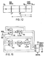
- Figure 16 shows in block form one type of circuit for generating vertical check words in the encoder.
- the input data is supplied to an input 100 which is connected to respective first inputs of two exclusive-OR circuits 101 and 102, and to a first input of a 3:1 selector 103.
- the output of the exclusive-OR circuit 101 is connected by way of a delay 104 to a second input of the selector 103, and also by way of the delay 104 back to a second input of the exclusive-OR circuit 101.
- the output of the exdusive-OR circuit 102 is connected by way of a PROM 105 and a delay 106 in series to a third input of the selector 103, and also by way of the PROM 105 and the delay 106 back to a second input of the exclusive-OR circuit 102.
- Respective clear signals are supplied to the delays 104 and 106, each of which has a delay corresponding to one row of an m x n array ( Figure 1), and a control signal is supplied to the selector 103.
- the output data with the vertical check words is supplied by the selector 103 to an output 107.
- the data is supplied in pre-formatted form to the input 100. That is to say, the data is grouped in sets of thirty-four rows (Figure 1) with gaps to receive the thirty-fifth and thirty-sixth rows of the m x n arrays, these last two rows consisting of the vertical check words.
- the vertical check words in the thirty-fifth row are simple parity check words formed by modulo-2 addition of the vertically aligned data words of the first thirty-four rows of the m x n array in the exclusive-OR circuit 101.
- the delay 104 is then cleared ready to start receiving data words from the next m x n array.
- the vertical check words in the thirty-sixth row are formed by modulo-2 addition of the vertically aligned data words of the first thirty-four rows of the m x n array in the exclusive-OR circuit 102, followed by successive shifting row by row in the PROM 105, as described above for example in connection with Figure 5, to form a Reed-Solomon b-adjacent code.
- the timing of the clear signals is arranged to avoid an unwanted additional shift in the PROM 105 to the time of the thirty-fifth row, that is the parity check word row.
- the timing of the control signal is such that the output supplied to the output 107 comprises the m x n arrays complete with the generated vertical check blocks.
- This generation of the vertical check words is preferably done before the above-described generation of the horizontal check words, but this is not essenti al.
- Figure 17 shows in block form one type of circuit for effecting this error correction on decoding.
- the input data with the vertical check words is supplied to an input 110 which is connected to a first input of an exclusive-OR circuit 111, to a first input of an exclusive-OR circuit 112, and to the input of a delay 113.
- the output of the exclusive-OR circuit 112 is connected by way of a delay 114 to a latch circuit 115 and so back to a second input of the exclusive-OR circuit 111.
- the syndrome 5 0 is developed at the output of the delay 114 and is supplied to one input of a 2:1 selector 116, the output of which is connected by way of a delay 117 back to a second input of the selector 116.
- the output of the delay 117 is also connected to one input of a comparator 118 so that a Chien search can be performed.
- the output of the exclusive-OR circuit 112 is connected by way of a delay 119 and a PROM 120 in series to a latch circuit 121 and so back to a second input of the exclusive-OR circuit 112.
- the syndrome S 1 is developed at the output of the PROM 120, which effects the necessary shifting to generate the syndrome S 1 , and is supplied to a first input of a 2:1 selector 122, the output of which is connected by way of a delay 123 and a PROM 124 in series to a second input of the comparator 118 and also back to a second input of the selector 122.
- the PROM 120 does the stepping back as described above to avoid reverse stepping in the Chien search.
- the output of the delay 117 is also connected by way of a latch circuit 125 to a first input of an exclusive-OR circuit 326.
- the output of the comparator 118 is connected by way of one input of a gate 127 to a clear terminal of the latch circuit 125.
- the gate 127 has another input to which an error correction control signal can be supplied. This error correction control signal may be used to disable the gate 127, for example, if the first step of the correction sequence reveals no errors. This is done because the horizontal check words provide the most accurate check on error words, and if they reveal none it is best to prevent error correction using the vertical check words as this may well result in erroneous correction.
- the output of the delay 113 is connected to a second input of the exclusive-OR circuit 126, the output of which is connected to an output 128.
- the delays 114, 117, 119 and 123 each have a delay corresponding to one row of an m x n array ( Figure 1), and the delay 113 has a delay corresponding to a complete m x n array.
- the syndromes S 0 and S 1 are generated and the PROM 124 shifts the syndrome S I row by row until the comparator 118 detects the identity that indicates that the position of the error word has been found. Thereupon the gate 127 enables the latch circuit 125 to supply the syndrome So to the exclusive-OR circuit 126 for modulo-2 addition to the error word to effect correction.
- Figure 18 shows a block of data words containing flagged error words ⁇ x and ⁇ y positioned a and b data words from the end of the data block, and the syndromes S 0 and S 1 These data words are assembled from one word of each block in any column of the array. Then: and But since a and b are known from the horizontal error detection process, ⁇ a and ⁇ b are known, so ⁇ X and ⁇ y can be deduced as follows From equation (33): Then modulo-2 addition of equations (34) and (35) gives: and in a similar manner:
- Figure 19 shows in block form a circuit for effecting this error correction on decoding. Parts of the circuit are similar in form and operation as corresponding parts in the circuit of Figure 17, and these parts are designed by the same reference numerals as in Figure 17 and will not be further described in detail.
- This circuit further comprises an error location store 130 to which error location signals are supplied by way of an error input 131 and converted, for example by a counter to 6-bit error addresses.
- error addresses are supplied to three PROMs 132, 133 and 134 which respectively derive the factors: and of equations (36) and (37). These factors are respectively supplied to three further PROMs 135, 136 and 137. Also supplied to the PROMs 135 and 136 is the syndrome So and to the PROM 137 is supplied the syndrome S 1 .
- the output of the PROM 135 is connected to a first input of an exclusive-OR circuit 138, the output of the PROM 136 is connected to a first input of an exclusive-OR circuit 139, and the output of the PROM 137 is connected to second Inputs of the exclusive-OR circuits 138 and 139.
- the outputs of the exclusive-OR circuits 138 and 139 are connected to a 2:1 selector 140, the output of which is connected to a latch circuit 141 which is controlled by a signal supplied over a line 142 from the error location store 130.
- the output of the latch circuit 141 is connected to one input of an exclusive-OR circuit 143 to a second input of which the data is supplied from the delay 113.
- the output of the exclusive-OR circuit 143 is connected to an output 144 of the circuit from which the corrected data is derived.
- the PROMs 135, 136 and 137 derive respective terms of the right-hand sides of equations (36) and (37), this being done either by multiplication of the various factors or by a log technique similar to that described in connection with the circuit of Figure 13.
- the exclusive-OR circuits 138 and 139 then form the requires values ⁇ x and ar y for supply to the exclusive-OR circuit 143 under control of the latch 141 to be modulo-2 added to the respective error words to effect correction thereof.
- the corrected data will, after use of the above three-step sequence, be supplied back to the part of the decoder shown in Figure 13 for further error correction and detection. Any remaining errors detected but not corrected with then be flagged as being in error, and subsequently be concealed.
- a two-step sequence is more appropriate, in which case, any blocks not corrected at the second stage will then be flagged as being in error and subsequently concealed.
- the methods and apparatus described are particularly advantageous when applied to digital television signals, there may be circumstances in which they can be applied to other forms of data.
- audio data in digital form, whether or not forming part of a digital television signal.
- 16-bit data words will normally be used, and each of these will be split into two 8-bit words for processing.
- the audio data words When forming part of a digital television signal the audio data words will be formed into separate arrays, similar in form to the m x n arrays of video data words described above, but smaller due in particular to the lower data rate of the audio information.
- the audio data will normally be in 16-bit word form and by dividing each 16-bit word irto two 8-bit words processing as described above can be used.
Landscapes
- Engineering & Computer Science (AREA)
- Multimedia (AREA)
- Signal Processing (AREA)
- Error Detection And Correction (AREA)
Applications Claiming Priority (2)
| Application Number | Priority Date | Filing Date | Title |
|---|---|---|---|
| GB08319404A GB2143659B (en) | 1983-07-19 | 1983-07-19 | Methods of and apparatus for correcting errors in binary data |
| GB8319404 | 1983-07-19 |
Publications (2)
| Publication Number | Publication Date |
|---|---|
| EP0132086A2 true EP0132086A2 (de) | 1985-01-23 |
| EP0132086A3 EP0132086A3 (de) | 1986-12-17 |
Family
ID=10545902
Family Applications (1)
| Application Number | Title | Priority Date | Filing Date |
|---|---|---|---|
| EP84304601A Withdrawn EP0132086A3 (de) | 1983-07-19 | 1984-07-05 | Verfahren und Anordnung zur Fehlerkorrektur in digitalen Daten |
Country Status (4)
| Country | Link |
|---|---|
| US (1) | US4607367A (de) |
| EP (1) | EP0132086A3 (de) |
| JP (1) | JP2570252B2 (de) |
| GB (1) | GB2143659B (de) |
Cited By (3)
| Publication number | Priority date | Publication date | Assignee | Title |
|---|---|---|---|---|
| EP0258721A1 (de) * | 1986-09-04 | 1988-03-09 | GRUNDIG E.M.V. Elektro-Mechanische Versuchsanstalt Max Grundig holländ. Stiftung & Co. KG. | Verfahren und Einrichtung zur Dropoutkompensation bei der Wiedergabe magnetisch aufgezeichneter Signale |
| EP0276991A1 (de) * | 1987-01-30 | 1988-08-03 | Sony Corporation | Verfahren und Gerät zum Kodieren von aufgezeichneten Daten mit einem Identifikationskode und einem Fehlerprüfkode |
| EP0217292A3 (en) * | 1985-09-30 | 1989-02-22 | Hitachi, Ltd. | A code error correcting method |
Families Citing this family (23)
| Publication number | Priority date | Publication date | Assignee | Title |
|---|---|---|---|---|
| US4949326A (en) * | 1986-12-10 | 1990-08-14 | Matsushita Electric Industrial Co., Ltd. | Optical information recording and reproducing system using optical disks having an error correction function |
| JPS62120670A (ja) * | 1985-11-20 | 1987-06-01 | Sony Corp | デ−タの誤り訂正方法 |
| US4729043A (en) * | 1985-12-11 | 1988-03-01 | American Telephone And Telegraph Company, At&T Bell Laboratories | Digital information storage and retrieval using video signals |
| CA1264091A (en) * | 1986-01-10 | 1989-12-27 | Yoichiro Sako | Generator for error correcting code and decoder for the code |
| AU594995B2 (en) * | 1986-01-24 | 1990-03-22 | Sony Corporation | Data transmission method suitable for a disc |
| US4796110A (en) * | 1986-02-18 | 1989-01-03 | Irwin Magnetic Systems, Inc. | System and method for encoding and storing digital information on magnetic tape |
| GB8631027D0 (en) * | 1986-12-30 | 1987-02-04 | Questech Ltd | Recording editing & moving television pictures |
| DE3804175A1 (de) * | 1988-02-11 | 1989-08-24 | Broadcast Television Syst | Verfahren und schaltungsanordnung zum einschreiben und auslesen eines digitalen halbleiterspeichers fuer videosignale |
| FR2634035B1 (fr) * | 1988-07-07 | 1994-06-10 | Schlumberger Ind Sa | Dispositif pour le codage et la mise en forme de donnees pour enregistreurs a tetes tournantes |
| DE3838234A1 (de) * | 1988-11-11 | 1990-05-17 | Broadcast Television Syst | Verfahren und schaltungsanordnung zur detektion und korrektur von fehlern in datenworten |
| US4965679A (en) * | 1989-02-27 | 1990-10-23 | Eastman Kodak Company | Method for electronically duplicating film images while maintaining a high degree of image quality |
| US4903141A (en) * | 1989-02-27 | 1990-02-20 | Eastman Kodak Company | Apparatus for electronically duplicating film images while maintaining a high degree of image quality |
| KR940011663B1 (ko) * | 1992-07-25 | 1994-12-23 | 삼성전자 주식회사 | 오류정정 시스템 |
| JP3318841B2 (ja) * | 1992-08-20 | 2002-08-26 | ソニー株式会社 | 再生装置および再生方法 |
| JP3328093B2 (ja) * | 1994-07-12 | 2002-09-24 | 三菱電機株式会社 | エラー訂正装置 |
| JPH1166762A (ja) * | 1997-08-08 | 1999-03-09 | Alps Electric Co Ltd | フロッピディスクシステム |
| US6781987B1 (en) * | 1999-10-19 | 2004-08-24 | Lucent Technologies Inc. | Method for packet transmission with error detection codes |
| EP1460765A1 (de) * | 2003-03-19 | 2004-09-22 | STMicroelectronics S.r.l. | Fehlerkorrekturmethode für als Symbolsequenz codierte digitale Daten |
| FR2860360B1 (fr) * | 2003-09-29 | 2005-12-09 | Canon Kk | Dispositif de codage /decodage utilisant un codeur/decodeur de reed-solomon |
| JP4619931B2 (ja) * | 2005-11-22 | 2011-01-26 | 株式会社東芝 | 復号装置、記憶装置および復号方法 |
| US12061793B1 (en) * | 2020-11-25 | 2024-08-13 | Astera Labs, Inc. | Capacity-expanding memory control component |
| US11722152B1 (en) | 2020-11-25 | 2023-08-08 | Astera Labs, Inc. | Capacity-expanding memory control component |
| US12277350B1 (en) | 2023-10-30 | 2025-04-15 | Astera Labs, Inc. | Virtual metadata storage |
Family Cites Families (12)
| Publication number | Priority date | Publication date | Assignee | Title |
|---|---|---|---|---|
| NL130511C (de) * | 1963-10-15 | |||
| US4211997A (en) * | 1978-11-03 | 1980-07-08 | Ampex Corporation | Method and apparatus employing an improved format for recording and reproducing digital audio |
| JPS55115753A (en) * | 1979-02-27 | 1980-09-05 | Sony Corp | Pcm signal transmission method |
| JPS55120250A (en) * | 1979-03-08 | 1980-09-16 | Sony Corp | Pcm signal transmitting method |
| JPS5661873A (en) * | 1979-10-25 | 1981-05-27 | Sony Corp | Digital video signal processor |
| US4375100A (en) * | 1979-10-24 | 1983-02-22 | Matsushita Electric Industrial Company, Limited | Method and apparatus for encoding low redundancy check words from source data |
| US4467373A (en) * | 1980-10-09 | 1984-08-21 | Micro Consultants Limited | Storage and retrieval of digital data on video tape recorders |
| US4371963A (en) * | 1980-12-24 | 1983-02-01 | Ncr Corporation | Method and apparatus for detecting and correcting errors in a memory |
| GB2095440B (en) * | 1981-03-23 | 1985-10-09 | Sony Corp | Digital television signal processing |
| JPS58147807A (ja) * | 1982-02-26 | 1983-09-02 | Toshiba Corp | 誤り訂正回路 |
| US4495623A (en) * | 1982-09-02 | 1985-01-22 | Discovision Associates | Digital data storage in video format |
| US4525838A (en) * | 1983-02-28 | 1985-06-25 | International Business Machines Corporation | Multibyte error correcting system involving a two-level code structure |
-
1983
- 1983-07-19 GB GB08319404A patent/GB2143659B/en not_active Expired
-
1984
- 1984-06-15 US US06/621,226 patent/US4607367A/en not_active Expired - Lifetime
- 1984-07-05 EP EP84304601A patent/EP0132086A3/de not_active Withdrawn
- 1984-07-16 JP JP59147410A patent/JP2570252B2/ja not_active Expired - Lifetime
Cited By (4)
| Publication number | Priority date | Publication date | Assignee | Title |
|---|---|---|---|---|
| EP0217292A3 (en) * | 1985-09-30 | 1989-02-22 | Hitachi, Ltd. | A code error correcting method |
| EP0258721A1 (de) * | 1986-09-04 | 1988-03-09 | GRUNDIG E.M.V. Elektro-Mechanische Versuchsanstalt Max Grundig holländ. Stiftung & Co. KG. | Verfahren und Einrichtung zur Dropoutkompensation bei der Wiedergabe magnetisch aufgezeichneter Signale |
| EP0276991A1 (de) * | 1987-01-30 | 1988-08-03 | Sony Corporation | Verfahren und Gerät zum Kodieren von aufgezeichneten Daten mit einem Identifikationskode und einem Fehlerprüfkode |
| US4910736A (en) * | 1987-01-30 | 1990-03-20 | Sony Corporation | Encoding method and apparatus for recording data with an identification code and an error check code |
Also Published As
| Publication number | Publication date |
|---|---|
| JPS6035833A (ja) | 1985-02-23 |
| JP2570252B2 (ja) | 1997-01-08 |
| GB2143659A (en) | 1985-02-13 |
| GB8319404D0 (en) | 1983-08-17 |
| GB2143659B (en) | 1986-11-05 |
| EP0132086A3 (de) | 1986-12-17 |
| US4607367A (en) | 1986-08-19 |
Similar Documents
| Publication | Publication Date | Title |
|---|---|---|
| US4607367A (en) | Correcting errors in binary data | |
| US4586183A (en) | Correcting errors in binary data | |
| US4476562A (en) | Method of error correction | |
| EP0170328B1 (de) | Einrichtung zur Fehlerkorrektur und Fehlermarkierung in einer Datengruppe und Wiedergabeanordnung für Video und/oder Audio die eine solche Einrichtung enthalten | |
| US4117458A (en) | High speed double error correction plus triple error detection system | |
| US4497058A (en) | Method of error correction | |
| US4546474A (en) | Method of error correction | |
| US4477903A (en) | Error correction method for the transfer of blocks of data bits, a device for preforming such a method, a decoder for use with such a method, and a device comprising such a decoder | |
| US4306305A (en) | PCM Signal transmitting system with error detecting and correcting capability | |
| US4569051A (en) | Methods of correcting errors in binary data | |
| US4486882A (en) | System for transmitting binary data via a plurality of channels by means of a convolutional code | |
| EP0072640A1 (de) | Verfahren zur Fehlerkorrektur von Daten | |
| EP0278383A2 (de) | Reed-Solomon Code verwendendes Fehler-Korrektur-Verfahren | |
| US3831144A (en) | Multi-level error detection code | |
| US4593394A (en) | Method capable of simultaneously decoding two reproduced sequences | |
| US4726028A (en) | Method for error detection and error correction | |
| GB1318250A (en) | Encoding detecting and or correcting of data | |
| US4521886A (en) | Quasi-soft decision decoder for convolutional self-orthogonal codes | |
| HK103688A (en) | System for the transmission of digital information signals | |
| JPH048974B2 (de) | ||
| US4873689A (en) | Method and apparatus for collecting errors in the digital data of a television signal | |
| JP2684031B2 (ja) | データの復号化方法 | |
| JP2604713B2 (ja) | 誤り訂正方法 | |
| KR920000396B1 (ko) | 에러정정방법(error訂正方法) | |
| GB2149156A (en) | A method of encoding and decoding |
Legal Events
| Date | Code | Title | Description |
|---|---|---|---|
| PUAI | Public reference made under article 153(3) epc to a published international application that has entered the european phase |
Free format text: ORIGINAL CODE: 0009012 |
|
| AK | Designated contracting states |
Designated state(s): AT DE FR GB NL |
|
| PUAL | Search report despatched |
Free format text: ORIGINAL CODE: 0009013 |
|
| AK | Designated contracting states |
Kind code of ref document: A3 Designated state(s): AT DE FR GB NL |
|
| 17P | Request for examination filed |
Effective date: 19870502 |
|
| 17Q | First examination report despatched |
Effective date: 19881005 |
|
| STAA | Information on the status of an ep patent application or granted ep patent |
Free format text: STATUS: THE APPLICATION IS DEEMED TO BE WITHDRAWN |
|
| 18D | Application deemed to be withdrawn |
Effective date: 19901124 |
|
| RIN1 | Information on inventor provided before grant (corrected) |
Inventor name: WILKINSON, JAMES HEDLEY Inventor name: IVE, JOHN GOODWIN SPENCER |