EP0132050B1 - Obturating structures and parts thereof - Google Patents
Obturating structures and parts thereof Download PDFInfo
- Publication number
- EP0132050B1 EP0132050B1 EP84304035A EP84304035A EP0132050B1 EP 0132050 B1 EP0132050 B1 EP 0132050B1 EP 84304035 A EP84304035 A EP 84304035A EP 84304035 A EP84304035 A EP 84304035A EP 0132050 B1 EP0132050 B1 EP 0132050B1
- Authority
- EP
- European Patent Office
- Prior art keywords
- latch
- bore
- pane
- hinge
- frame
- Prior art date
- Legal status (The legal status is an assumption and is not a legal conclusion. Google has not performed a legal analysis and makes no representation as to the accuracy of the status listed.)
- Expired
Links
- 238000007789 sealing Methods 0.000 claims description 8
- 239000011521 glass Substances 0.000 claims description 7
- 238000009423 ventilation Methods 0.000 claims description 5
- 238000009434 installation Methods 0.000 claims description 4
- 239000005060 rubber Substances 0.000 claims description 3
- 239000000853 adhesive Substances 0.000 claims description 2
- 230000001070 adhesive effect Effects 0.000 claims description 2
- 239000003292 glue Substances 0.000 claims description 2
- 230000000712 assembly Effects 0.000 claims 1
- 238000000429 assembly Methods 0.000 claims 1
- 230000001419 dependent effect Effects 0.000 claims 1
- 239000000463 material Substances 0.000 description 13
- 239000004033 plastic Substances 0.000 description 7
- 229920003023 plastic Polymers 0.000 description 7
- XLYOFNOQVPJJNP-UHFFFAOYSA-N water Substances O XLYOFNOQVPJJNP-UHFFFAOYSA-N 0.000 description 7
- 238000004519 manufacturing process Methods 0.000 description 5
- 239000011324 bead Substances 0.000 description 3
- 230000000694 effects Effects 0.000 description 3
- 238000001125 extrusion Methods 0.000 description 3
- 238000012423 maintenance Methods 0.000 description 3
- 238000003825 pressing Methods 0.000 description 3
- 229910052782 aluminium Inorganic materials 0.000 description 2
- XAGFODPZIPBFFR-UHFFFAOYSA-N aluminium Chemical compound [Al] XAGFODPZIPBFFR-UHFFFAOYSA-N 0.000 description 2
- 238000005452 bending Methods 0.000 description 2
- 238000005520 cutting process Methods 0.000 description 2
- 239000002783 friction material Substances 0.000 description 2
- 229910052751 metal Inorganic materials 0.000 description 2
- 239000002184 metal Substances 0.000 description 2
- 239000007787 solid Substances 0.000 description 2
- 241000192308 Agrostis hyemalis Species 0.000 description 1
- 230000005540 biological transmission Effects 0.000 description 1
- 230000001627 detrimental effect Effects 0.000 description 1
- 238000009413 insulation Methods 0.000 description 1
- 238000003754 machining Methods 0.000 description 1
- 238000005399 mechanical ventilation Methods 0.000 description 1
- 238000003860 storage Methods 0.000 description 1
- 229920001187 thermosetting polymer Polymers 0.000 description 1
- 238000005406 washing Methods 0.000 description 1
Images


Classifications
-
- E—FIXED CONSTRUCTIONS
- E06—DOORS, WINDOWS, SHUTTERS, OR ROLLER BLINDS IN GENERAL; LADDERS
- E06B—FIXED OR MOVABLE CLOSURES FOR OPENINGS IN BUILDINGS, VEHICLES, FENCES OR LIKE ENCLOSURES IN GENERAL, e.g. DOORS, WINDOWS, BLINDS, GATES
- E06B3/00—Window sashes, door leaves, or like elements for closing wall or like openings; Layout of fixed or moving closures, e.g. windows in wall or like openings; Features of rigidly-mounted outer frames relating to the mounting of wing frames
- E06B3/04—Wing frames not characterised by the manner of movement
- E06B3/28—Wing frames not characterised by the manner of movement with additional removable glass panes or the like, framed or unframed
-
- E—FIXED CONSTRUCTIONS
- E05—LOCKS; KEYS; WINDOW OR DOOR FITTINGS; SAFES
- E05C—BOLTS OR FASTENING DEVICES FOR WINGS, SPECIALLY FOR DOORS OR WINDOWS
- E05C9/00—Arrangements of simultaneously actuated bolts or other securing devices at well-separated positions on the same wing
- E05C9/08—Arrangements of simultaneously actuated bolts or other securing devices at well-separated positions on the same wing with a rotary bar for actuating the fastening means
-
- E—FIXED CONSTRUCTIONS
- E05—LOCKS; KEYS; WINDOW OR DOOR FITTINGS; SAFES
- E05D—HINGES OR SUSPENSION DEVICES FOR DOORS, WINDOWS OR WINGS
- E05D1/00—Pinless hinges; Substitutes for hinges
- E05D1/04—Pinless hinges; Substitutes for hinges with guide members shaped as circular arcs
-
- E—FIXED CONSTRUCTIONS
- E06—DOORS, WINDOWS, SHUTTERS, OR ROLLER BLINDS IN GENERAL; LADDERS
- E06B—FIXED OR MOVABLE CLOSURES FOR OPENINGS IN BUILDINGS, VEHICLES, FENCES OR LIKE ENCLOSURES IN GENERAL, e.g. DOORS, WINDOWS, BLINDS, GATES
- E06B3/00—Window sashes, door leaves, or like elements for closing wall or like openings; Layout of fixed or moving closures, e.g. windows in wall or like openings; Features of rigidly-mounted outer frames relating to the mounting of wing frames
- E06B3/02—Wings made completely of glass
-
- E—FIXED CONSTRUCTIONS
- E05—LOCKS; KEYS; WINDOW OR DOOR FITTINGS; SAFES
- E05Y—INDEXING SCHEME ASSOCIATED WITH SUBCLASSES E05D AND E05F, RELATING TO CONSTRUCTION ELEMENTS, ELECTRIC CONTROL, POWER SUPPLY, POWER SIGNAL OR TRANSMISSION, USER INTERFACES, MOUNTING OR COUPLING, DETAILS, ACCESSORIES, AUXILIARY OPERATIONS NOT OTHERWISE PROVIDED FOR, APPLICATION THEREOF
- E05Y2800/00—Details, accessories and auxiliary operations not otherwise provided for
- E05Y2800/67—Materials; Strength alteration thereof
- E05Y2800/672—Glass
-
- E—FIXED CONSTRUCTIONS
- E05—LOCKS; KEYS; WINDOW OR DOOR FITTINGS; SAFES
- E05Y—INDEXING SCHEME ASSOCIATED WITH SUBCLASSES E05D AND E05F, RELATING TO CONSTRUCTION ELEMENTS, ELECTRIC CONTROL, POWER SUPPLY, POWER SIGNAL OR TRANSMISSION, USER INTERFACES, MOUNTING OR COUPLING, DETAILS, ACCESSORIES, AUXILIARY OPERATIONS NOT OTHERWISE PROVIDED FOR, APPLICATION THEREOF
- E05Y2900/00—Application of doors, windows, wings or fittings thereof
- E05Y2900/10—Application of doors, windows, wings or fittings thereof for buildings or parts thereof
- E05Y2900/13—Type of wing
- E05Y2900/132—Doors
-
- Y—GENERAL TAGGING OF NEW TECHNOLOGICAL DEVELOPMENTS; GENERAL TAGGING OF CROSS-SECTIONAL TECHNOLOGIES SPANNING OVER SEVERAL SECTIONS OF THE IPC; TECHNICAL SUBJECTS COVERED BY FORMER USPC CROSS-REFERENCE ART COLLECTIONS [XRACs] AND DIGESTS
- Y10—TECHNICAL SUBJECTS COVERED BY FORMER USPC
- Y10T—TECHNICAL SUBJECTS COVERED BY FORMER US CLASSIFICATION
- Y10T292/00—Closure fasteners
- Y10T292/08—Bolts
- Y10T292/1043—Swinging
- Y10T292/1044—Multiple head
- Y10T292/1045—Operating means
- Y10T292/1047—Closure
Definitions
- the present invention relates to obturating structures comprising a hinged frame holding a pane of glass or panel of other material, for use in closing an opening in a wall or the like, and also relates to parts of said structures which have inherent novel features, alone or in combination with one or more other parts.
- the opening may be unobstructed when the obturating structure is in the open position, or it may contain some other closure means, such as a window or door.
- the obturating structure itself may be a window for fitting in or over said opening, or for providing a double-glazing fixture secured inside or outside an existing window.
- the obturating structure may be fitted inside or outside to reduce heat-loss, or provide improved security.
- a casement window comprising a window frame and at least one frameless leaf of plate or armoured glass hingedly connected to one side member of said window frame by a first hinge member secured to and extending continuously along one side edge of the leaf and cooperating with a second hinge member extending continuously along the said window frame member and providing with said first hinge member a weatherproof seal between the leaf and the window frame member.
- One hinge member may be a cylindrical bead extending lengthwise, and the other hinge member provides a part-cylindrical cavity to receive the bead and pivotally support the leaf, which is inserted in a continuous channel carried on a web extending from the bead portion of the one hinge member.
- the web and channel obscures view and light in a significant strip adjacent the associated member of the window frame, which is an undesirable feature for modern window structures.
- One object of the present invention is to provide such a structure and the parts thereof.
- the present invention comprises an obturating structure for closing an opening in a wall, for example, a window, hatch, shutter or door, comprising at least one frame member (1) having a longitudinal bore (4) of generally cylindrical internal contour with a longitudinal opening having an arcuate width less than 180° but more than 90°, and at least one co-operating hinge (3) shaped to provide a weather-proof assembly in conjunction with said frame member, characterised in that said or each hinge (3) is a generally cylindrical member or assembly (3, 22) having external dimensions such that it may be securely contained in said bore, said or each cylindrical member or assembly (3, 22) being provided with a slot (21) in which can be fixed a pane or panel extending into said bore and so be pivotally secured to said frame member (1).
- each hinge is a generally cylindrical member or assembly having external dimensions such that it may be securely contained in said bore, it can be provided with a slot in which a pane or panel can be fixed so as to be pivotally secured to said frame member.
- the structure is formed of a plurality of said frame members (1) having a common cross-section which are assembled together around a pane or panel, that the bore (4) of one contains at least one hinge (3), and that the bore of at least one other frame member contains one or more latches (2) turnable to one extreme position which locks the pane and to another position which releases the locking.
- At least one frame member has a receiving aperture shaped to accept a seal cover which can be inserted and sealed to an adjacent wall surface or accepted into a similar receiving aperture in an adjacent frame member to complete a weather-proof seal, when fitted.
- Such structures and their parts which can be adapted simply to openings of different sizes, and which can be mounted in place for left-handed, ' right-handed, top or bottom opening.
- a further object is to construct the whole frame from the same material, further reducing manufacturing and storage costs.
- a window structure constructed according to the invention can be specifically intended for use together with a sashless window pane, especially together with an additional-window structure according to Finnish Patent 58 674.
- a sashless window pane is easy to wash but, in order to close tightly, it requires a relatively large number of fastening furniture-elements.
- Conventional latches and other window furniture form protrusions which complicate washing and other maintenance and, furthermore, increase the otherwise economical price of a sashless pane.
- a further object of the present invention is therefore to provide latches and hinges that are inexpensive to manufacture, which leave the pane surface maximally bare, and can be installed at any requisite point in the window frame without specific fastening devices.
- seal covers are of metal, plastic or rubber, and they are generally used in conjunction with metal frames.
- the seal cover is secured on the one hand to the frame of a window or the like and on the other hand to the surrounding opening in the wall.
- the window opening is adapted to the window size, there appears, however, some variation in the dimensions between them. Therefore, the seal cover must also have the respective variation of dimensions in order that its securing to the frame and the wall be successful. Consequently; seal covers of different dimensions must be manufactured and, above all, on the site there must be on hand seal covers of different dimensions, from among which the suitable one is selected for each place. An even greater difficulty is encountered when there is variation in the dimensions of a window opening, which is by no means unusual.
- a further object of the present invention is therefore to eliminate the said disadvantages and to provide a seal cover, the design of which is such that it can be fitted as an effective seal between the frame and the wall or the adjacent window, even if the clearance varies significantly.
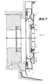
- Figure 2 shows a vertical section on the line II-II of Figure 1, showing the cross-section of each frame member 1.
- the frame structure is installed in the frame-work of an old exterior window and forms an additional outer window structure which protects the old frame and sash parts and provides thermal and sound insulation.
- the essential parts of the frame cross-section include an open bore 4 which receives the pane, sealing grooves 5 into which respective pane seals 6 are fitted at each edge of the pane, an exterior smooth part 7 which forms the outer visible surface and which can be painted in a suitable colour or covered with a suitable cover strip, and a frame support part 8 by which the frame is secured to the window structure.
- the support part 8 has a groove for a seal 9 which is pressed against the underlying surface.
- the support part 8 is the rigid part that gives the frame structure the required strength and rigidity.
- the arcuate width of the longitudinal opening in the bore 4 is preferably from 100° to 120°.
- the hinges and latches fitted in the open tube remain securely inside the tube, since their outer diameter can be the same as that of the inner diameter of the open bore, or can be made so by an additional sleeve, as will be described later.
- a groove 10 in the open bore 4 is clearly visible in the Figure, and the lower frame part is provided with perforations 11 for the removal of water.
- the groove 10 has been fitted between the exterior smooth part 7 and the support part 8, whereby water can suitably run off along the wall of the support part 8.
- the open structure of the frame provides a certain adjustment tolerance with respect to the pane size.
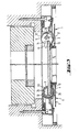
- Figure 3 depicts the same window structu re, as a horizontal section along the line III-III of Figure 1, passing through a latch 2 and a hinge 3.
- the latch 2 is seen as a substantially circular piece fitted in the open bore 4.
- the outer diameter of the latch 2 and the inner diameter of the open bore 4 are the same, and their cross-sectional surfaces substantially correspond to each other.
- a small wedge-like piece has been removed from the circumference of the latch in orderto form a locking shoulder 11.
- the interior edge 12 of the open bore presses against the locking shoulder 11.
- the latch 2 moves to a somewhat eccentric position in relation to the open bore, at which time the latch wedges between the interior edge 12 and the interior surface of the circumference ending at the remote exterior edge 13.
- the latch 2 has a notch 14formed in the circumference, in which the edge of the pane can be locked.
- the notch 14 allows a small tolerance for pane size.
- the latch is released by pressing the latch between the locking shoulder 11 and the grip 15, which moves the locking shoulder inside the edge 12 so thatthe latch itself moves back to a central position in relation to the open bore, whereby the wedge effect is eliminated and the latch can turn clockwise to release the pane edge.
- the locking position of the latch is depicted in Figure 7a and the releasing position in Figure 7b.
- an alternative circumferential shape of the latch can be used, in which a segment- shaped piece has been removed.
- This shape helps in removal of the latch from the open bore by turning the latch counterclockwise, with the pane positioned out of the way, so that it does not come between the latch and the seal, in which case the narrower width at the segment in question facilitates the removal of the latch from between the open-bore edges 12 and 13.
- Latches of this shape can be very simply added to the window structure and also removed from it while the window is open.
- the latch preferably has a longitudinal axial opening 17, shown as having the shape of a semicircle in Figures 3, and 8.
- the opening 17 can be used when forming a long latch, such as shown in Figure 8a, which is an embodiment made up of three latches through which a common torsionally rigid rod 18 has been passed.
- a long latch such as shown in Figure 8a, which is an embodiment made up of three latches through which a common torsionally rigid rod 18 has been passed.
- the middle latch is provided with a locking shoulder 11, and the locking and opening of the entire latch assembly is effected by turning this latch, and by pressing it in.
- the latches at the ends of the long latch turn with the rod 18 and produce the same gripping effect as does the middle latch.
- Separate latches may be secured in place in the open bore byfictional clipsthatform latch rings 19, examples of which are shown in Figures 8a and 8b. These are shaped to grip within the bore, when inserted therein.
- the latches can be secured in place in a simple way by cutting the edges 12 and 13 of the open bore above and below the latches, whereby simple deformations can form stops in the open bore to prevent longitudinal movement.
- FIGs 3, 4, 5a, 5b and 6 depict the structure and operation of exemplary embodiments of a hinge according to the invention.
- the embodiment shown in Figure 4 is an assembly made up of a cylindrical hinge 3 which has a notch 21 in wich the obturating pane or panel is secured, for example by glue or putty in the case of a glazed structure, or by mechanical means if a solid panel is to be provided, for enhanced security or privacy.
- a bearing sleeve 22 Over the hinge 3 there is a bearing sleeve 22, the outer diameter of which corresponds to the inner diameter of the open bore and the inner diameter of which corresponds to the outer diameter of the hinge.
- the bearing 22 is preferably of plastic or some other low-friction material.
- the hinge to be mounted in the lower corner of the window is detachably fastened to a hemispherical bearing 23, which forms a readily moving hinge bearing in the corner of the window in this illustrated embodiment.
- the bearing 23 is preferably of a thermosetting plastics material or the like.
- Parallel to the notch 21 the hinge has axial bores 24 which reduce the material content, so reducing the weight, and at the same time providing an opportunity to attach additional members to the hinge.
- Figure 6 shows an embodiment with a flat spring 25 secured at one end in the bore opening 24, and to the frame member 1 (not shown) at its other end. The flat spring thus fitted causes the window to open automatically when the latch is released . from the locking position.
- the pane-securing notch 21 is preferably formed eccentrically in the hinge piece, i.e.
- the diameters of the hinge 3 and the bearing 22 have been selected in such a way that when the hinge is enclosed within its bearing it can not come out of the open bore, whereas if the bearing has been pushed off the hinge, the hinge itself can pass through the opening.
- the interior surface of the bearing 22 can also function as the primary bearing surface, in which case the hinge 3 slides against the said interior surface. In this case the bearing 22 has approximately the same cross-sectional shape as the open bore.
- the hinge according to the invention also functions well without a detachable bearing.
- the hinge must be coated, covered with, or completely formed from, a suitable low-friction material.
- the pane with its hinges 3 must be fitted in the open bore 4 of its frame member 1 before the frame structure is secured together at the corners.
- latches and hinges according to the invention can also be used in conjunction with other obturating structures, such as doors, hatches, covers, etc., as long as the or each hinge and latch are fitted in an open-bore frame structure.
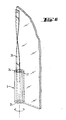
- Figure 9 shows a horizontal cross-section of the right-hand frame member 32 of a window pane structure, the frame member having a pocket-like opening 33.
- the edge 31a a of a seal cover 31 is pushed into the opening 33, and its other edge 31b has been bent into an L-shape arm and is sealed against an adjacent wall by a sealing tape.
- Two intermediate installation stage positions of the seal cover are illustrated by dotted lines in the Figure.
- the edge 31a is simply pushed so deep into the opening 33 that the arm 31 b reaches a suitable sealing distance from the wall. If the clearance between the frame member and the wall is narrower or wider at some distance from this point, the edge 31a will be less deep in the opening 33 or respectively deeper in the opening 33 at that window height.
- the seal cover must be bent at another point so that the arm 31 b becomes wider. This is an easy step, since the material of the seal cover is easy to work, and the mere bending is not difficult.
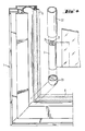
- Figure 10 schematically depicts a rectangular seal cover 31' fitted between the frame member of two adjacent window structures.
- the width of this' clearance has been precisely defined in advance, and the width of the seal cover is selected suitably so that it can first be pushed to the bottom of the opening in one frame, when its other edge can enter the opening in the other frame member, and the seal cover can then be moved to a central position, as shown.
- Figure 11 illustrates two rectangular window structures fitted into a single slanted window opening. Nevertheless, the seal cover 32 neatly covers the clearance between the frame member and the wall, and there have been no difficulties in installing the seal cover, as is seen more clearly in the enlarged fragmentary view of the right-hand top corner of the Figure 11 arrangement, which is shown in Figure 12.
- the invention is based on the main idea that the essential part of the frame structure encircling the pane or panel is made up of a tube of a substantially circular cross-section, which is open by a longitudinal slot of a certain size, in other words an open bore member. Both hinges and latches can be fitted in their respective bores.
- the tube bore functions at the same time as a water collector and a pressure-equalizing turbulence chamber if water or air penetrates inside the glass under some circumstances, for example in a case in which some latch is not properly closed.
- In the tube there is preferably formed a longitudinal groove in which any water entering the tube accumulates. The water flows out of the structure through perforations formed in the groove, or at a corresponding point in the tube.
- the said groove is produced in the frame member during its manufacturing process, at the extrusion stage. The groove is thus present in every part of the frame, but water removal perforations can be formed later at any desired points in the lower part of the frame.
- the arcuate width of the open slot removed from the tube is at least 90°, and is preferably within the range of approximately 100° to 130°, but the opening is less than 180°, so that the hinges and latches operating in it remain secured within the tube.
- Such an opening size enables the pane to open 90°.
- the edges of the open bore cooperate with the latch operating in such a way that a shoulder formed on the circumference of the latch presses against one edge of the open tube, while the remote side of the circumference of the latch presses as a wedge against the pane edge at the opposite edge of the open tube, thus producing the locking action of the latch.
- the frame member additionally includes a sealing groove into which a suitable seal is fastened for the pane, an external smooth part which forms most of the outwardly visible surface and can be given a treatment matching the outward appearance of the building, or covered with a cover strip of the desired type, and incorporates a frame support part which gives the structure rigidity, and by which the frame is secured to the window opening or to an old window, in the case of glazing applications.
- a window frame from the window members is simple.
- the different parts of the frame are simply cut at an angle of 45° in relation to their longitudinal direction, and are fastened to each other in a conventional manner.
- the window structure is symmetrical in relation to the horizontal axis, and so it is not necessary at the manufacturing stage to take account of whether the obturating structure will be left-handed or right-handed.
- Suitable hinges and latches constructed in accordance with the invention can be fitted in the window frame after the frame members have been joined together, and so the hinging side can be easily altered after the window structure according to the invention is installed in place.
- the frame member is preferably made from aluminum, the excellent extrusion properties of which can be exploited in the best possible manner both technically and economically.
- Both the hinges and the latches can be manufactured from an extruded bar-like material without any machining other than cutting, which, of course, means very low manufacturing costs.
- the hinges may be made from aluminum or a plastics material, and the latches preferably from plastics material.
- the hinge is made up of a cylindrical part to which the pane is secured in a suitable manner.
- the cylindrical part has, for example, a notch in which the edge of the pane is glued or secured by putty, in the case of glass.
- Around the bar-like part of the hinge there is preferably a separate seleve made from plastics material or some similar material, which forms a bearing surface for the bar-like part when it turns in the open tube.
- the sleeve-like bearing surface can also slide against the open tube. This enables the window pane, secured to the hinges, to be removed from the open tube of the frame, since the width of the opening in the open bore is the same or slightly greater than the hinge diameter.
- the sleeve fitted over the hinge increases the hinge diameter so that the hinge cannot come out of the frame.
- the sleeve has preferably the same diameter as the open tube, not taking account of the groove formed in the open tube.
- the cylindrical hinge part can itself function as a bearing surface against the interior wall of the open bore, in which case the hinge is preferably of plastics material.
- Any corner hinges of the window pane are preferably each fitted with a detachably fastened hemispherical bearing piece, the hinge then rotating whilst supported by it.
- the exterior shape of the bearing piece corresponds to the frame corner formed by the open bores.
- the bearing piece at the upper corner has no function in use of the window pane, but it promotes safe transport of the pane in its frame structure. Fitting a bearing piece at both corners also enables the structure to be turned upside down if the opening direction of the window so requires.
- Hinges can be secured to the pane in such a number that a tight closing is achieved against the seal of the frame.
- the hinge structure is such that the hinges are automatically on the same axis, and so no stresses detrimental for the functioning of the window are created.
- the hinge structure allows the pane to open 90°, which is sufficient for the maintenance of the window and for ventilation.
- the cylindrical hinge there are preferably formed in its transverse direction one or two openings having a crescent-shaped cross-section.
- the purpose of the openings is to lighten the structure, to save material, and to provide an opportunity to attach an additional member to the hinge. It is possible, for example, to attach a flat spring to the hinge to cause the pane to open automatically when the latch releases the pane, or respectively to cause the pane to close. It is thus possible to replace with the flat spring fitted to the hinge the so-called wind latch necessary in a ventilation window, which keeps two ventilation windows locked to each other.
- the flat spring can also be installed in such a way that it keeps the pane closed against the seals, in which case the pane can be used, for example, for obtaining replacement air in connection with mechanical ventilation in such a way that in the manner of a back-pressure valve it prevents a possible underpressure from being discharged from the room space.
- the latch structure according to the invention is made up of a piece of plastic or other suitable material, rotating inside the open tube of the frame and having on one side a notch for the pane. Immediately adjacent to the notch there is preferably a protrusion which can be pressed to close the latch. Furthermore, on the circumference of the latch there is a locking shoulder, which presses against one edge of the open bore of the frame member, whereby the latch piece forms a kind of wedge between the two edges of the open tube and at the same time presses the pane edge against the frame seal. The locking shoulder can be released by pressing the latch at the opening of the open tube, at which time the latch turns inside the tube and the pane edge is released.
- the latch has advantageously an axial bore with a cross-section of the shape of, for example, a circle segment. The purpose of the opening is to lighten the structure or to create room for a member to be attached therein.
- a segment is preferably removed along the circumference of the latch, approximately opposite the notch.
- the width of the latch in the segment area is approximately the same as or somewhat smaller than the distance between the edges of the open bore.
- a latch without the said segment cut away can be removed from the open tube when the pane is open and the latch is at a certain angle of rotation.
- the latches are locked in place longitudinally in the open bore by means of, for example, latch rings, or simply by bending the edges of the open tube inwardly above and below the latches. In each case, the necessary number of latches are fitted in the frame member on the sides requiring them, in accordance with the window size, wind conditions, etc.
- a latch at the lower edge of the window also serves as a bearing member when a wide window is concerned.
- latch assembly formed from latches according to the invention, having several latches linked together in order to provide several gripping points on a common torsionally rigid rod, around which the desired number of these latches are fitted.
- One latch forms an operating and locking piece.
- the cross-section of the other latches is generally the same as that of the locking piece, but without the locking shoulder described above. They keep the pane gripped by torsion-rod transmission.
- the structure according to the invention may be used together with a frame member which has a pocket-like opening into which one flat edge of a seal cover is simply pushed and secured to it by means of a spring or a screw, for example.
- the other edge of the seal cover is flat or L-shaped to give a small bent arm.
- the securing to the surrounding wall is carried out either by an adhesive sealing tape attached to the bend, a rubber seal cover fitted to the edge, or simply by clamping the seal cover between the structure and the adjacent wall. If the other edge of the seal cover is secured to an adjacent window, this is done in the same way as the securing of the first edge.
- a seal which expands under the effect of moisture after its installation and thus produces an effective seal. If the window opening is slanted and the frame of the window is rectangular throughout, the clearance produced is covered by the seal cover according to the invention, the straight edge of the seal cover pushing to a different depth in the opening in the frame, and the seal cover being thus adjustable without steps.
- seal cover which serves as an intermediate sheet, both its edges being flat.
- the seal cover is first pushed into the pocket in one frame, so deeply that the other edge of the seal cover can be pushed into the opposite pocket in the second frame.
- the seal cover according to the invention can also be installed as a horizontal seal cover at the upper or lower edge of the window.
- a seal cover bent into a suitable shape can be fitted to serve as a drip sheet or guttering at the lower edge of the frame.
Landscapes
- Engineering & Computer Science (AREA)
- Mechanical Engineering (AREA)
- Civil Engineering (AREA)
- Structural Engineering (AREA)
- Securing Of Glass Panes Or The Like (AREA)
- Hooks, Suction Cups, And Attachment By Adhesive Means (AREA)
Applications Claiming Priority (4)
| Application Number | Priority Date | Filing Date | Title |
|---|---|---|---|
| FI832196 | 1983-06-16 | ||
| FI832196A FI67912C (fi) | 1983-06-16 | 1983-06-16 | Foensterkonstruktion och gaongjaern och laos som laempar sig foer denna |
| FI833942A FI833942A7 (fi) | 1983-10-27 | 1983-10-27 | Taeckprofil foer foensterram eller liknande ram. |
| FI833942 | 1983-10-27 |
Publications (3)
| Publication Number | Publication Date |
|---|---|
| EP0132050A2 EP0132050A2 (en) | 1985-01-23 |
| EP0132050A3 EP0132050A3 (en) | 1985-08-21 |
| EP0132050B1 true EP0132050B1 (en) | 1988-03-23 |
Family
ID=26157465
Family Applications (1)
| Application Number | Title | Priority Date | Filing Date |
|---|---|---|---|
| EP84304035A Expired EP0132050B1 (en) | 1983-06-16 | 1984-06-15 | Obturating structures and parts thereof |
Country Status (6)
| Country | Link |
|---|---|
| US (1) | US4562668A (da) |
| EP (1) | EP0132050B1 (da) |
| CA (1) | CA1268378A (da) |
| DE (1) | DE3470076D1 (da) |
| DK (1) | DK164292C (da) |
| NO (1) | NO161515C (da) |
Families Citing this family (10)
| Publication number | Priority date | Publication date | Assignee | Title |
|---|---|---|---|---|
| US4878314A (en) * | 1988-10-05 | 1989-11-07 | Blockinger Larry A | High security window |
| GB9305596D0 (en) * | 1993-03-18 | 1993-05-05 | Aludex Limited | Improvements in or relating to hinges |
| FR2708962A1 (fr) * | 1993-08-13 | 1995-02-17 | Rouere De Richard | Dispositif mécanique à commande centralisée destiné à assurer un verrouillage simultané de tampons de sol placés en série. |
| US5551197A (en) | 1993-09-30 | 1996-09-03 | Donnelly Corporation | Flush-mounted articulated/hinged window assembly |
| US7838115B2 (en) * | 1995-04-11 | 2010-11-23 | Magna Mirrors Of America, Inc. | Method for manufacturing an articulatable vehicular window assembly |
| US6145165A (en) * | 1998-10-13 | 2000-11-14 | Alwind Industries, Ltd. | Hinge mechanism |
| US20100107497A1 (en) * | 2008-11-05 | 2010-05-06 | Magna Mirrors Of America, Inc. | Full view storm door |
| US8276409B2 (en) * | 2009-11-05 | 2012-10-02 | Magna Mirrors Of America, Inc. | Glass appliance cover with bonded hardware |
| US20110265389A1 (en) * | 2010-05-03 | 2011-11-03 | Zarges Aluminum Systems Llc | System and Method for Securing a Door Assembly to a Structure |
| DE202013101374U1 (de) * | 2013-03-28 | 2013-04-12 | Igus Gmbh | Axial-Radial-Gleitlager mit Polymergleitelementen und entsprechendes Gleitelement |
Family Cites Families (9)
| Publication number | Priority date | Publication date | Assignee | Title |
|---|---|---|---|---|
| DE403030C (de) * | 1922-10-13 | 1924-09-24 | Gaetan Prosper Lievre Dr | Vorrichtung zur selbsttaetigen Sperrung von Automobilfensterrahmen, Fluegeltueren usw |
| US1711213A (en) * | 1927-11-14 | 1929-04-30 | John R Smith | Door-latch mechanism |
| US2352727A (en) * | 1942-12-15 | 1944-07-04 | Hugh C Mcmahon | Safety windshield and mounting |
| US2845665A (en) * | 1956-04-02 | 1958-08-05 | Andrew S Place | Window structure |
| US2924862A (en) * | 1959-02-26 | 1960-02-16 | Albert P Pellicore | Securing means for window guards and the like |
| GB960166A (en) * | 1961-08-10 | 1964-06-10 | Faulkner Greene And Company Lt | Improvements in or relating to windows |
| US3266192A (en) * | 1963-07-24 | 1966-08-16 | Arthur H Kolm | Window sash assembly |
| US3633244A (en) * | 1968-11-25 | 1972-01-11 | Abraham Grossman | Hinge construction |
| US3877740A (en) * | 1972-08-29 | 1975-04-15 | Zimmerman C Michael | Tubular deadlock for securing windows and doors closed |
-
1984
- 1984-06-05 US US06/617,539 patent/US4562668A/en not_active Expired - Fee Related
- 1984-06-15 CA CA000456679A patent/CA1268378A/en not_active Expired - Fee Related
- 1984-06-15 DE DE8484304035T patent/DE3470076D1/de not_active Expired
- 1984-06-15 EP EP84304035A patent/EP0132050B1/en not_active Expired
- 1984-06-15 NO NO842424A patent/NO161515C/no unknown
- 1984-06-15 DK DK293784A patent/DK164292C/da not_active IP Right Cessation
Also Published As
| Publication number | Publication date |
|---|---|
| EP0132050A3 (en) | 1985-08-21 |
| CA1268378A (en) | 1990-05-01 |
| DK293784A (da) | 1984-12-17 |
| EP0132050A2 (en) | 1985-01-23 |
| US4562668A (en) | 1986-01-07 |
| NO161515C (no) | 1989-08-23 |
| NO842424L (no) | 1984-12-17 |
| DK164292B (da) | 1992-06-01 |
| DK164292C (da) | 1992-10-26 |
| NO161515B (no) | 1989-05-16 |
| DE3470076D1 (en) | 1988-04-28 |
| DK293784D0 (da) | 1984-06-15 |
Similar Documents
| Publication | Publication Date | Title |
|---|---|---|
| US4369828A (en) | Supplemental window and blind unit | |
| EP1350901B1 (en) | A roof window with main frame and sash covering members | |
| US4001972A (en) | Prefabricated pre-hung combination storm and screen door and method for installing the same | |
| DK171536B1 (da) | Vindue med ramme af ekstruderede profilemner | |
| EP1464787B1 (de) | Container mit Fenster | |
| EP0132050B1 (en) | Obturating structures and parts thereof | |
| US4763446A (en) | Low sound, thermal and air penetration sliding window | |
| US7765741B2 (en) | Movable light latch | |
| US6094874A (en) | Window mount system | |
| EP3071775B1 (en) | Invisible window frame | |
| CA1262077A (en) | Outwardly opening hinged window assembly | |
| US4877076A (en) | Screen unit with built-in blind | |
| US3295259A (en) | Sashless sliding window system | |
| EP2105569A1 (en) | Window assembly | |
| US7730689B2 (en) | Window arrangement to aid in the reduction of unwanted air movement in or out of windows | |
| JPH0428393Y2 (da) | ||
| US10612293B1 (en) | Storm or secondary window installation system and method of installation | |
| EP1558824B1 (en) | Burglar proof roof window | |
| FR2745027B1 (fr) | Chassis ouvrant de survitrage a fixer sur des montants vitres de fenetres | |
| KR102152139B1 (ko) | 시스템 창호 | |
| FI67912B (fi) | Foensterkonstruktion och gaongjaern och laos som laempar sig foer denna | |
| EP3985192A1 (en) | A roof window having a casement openable to the exterior to a position parallel to the plane of the roof | |
| JPH022850Y2 (da) | ||
| JPS634149Y2 (da) | ||
| GB2116617A (en) | Frames |
Legal Events
| Date | Code | Title | Description |
|---|---|---|---|
| PUAI | Public reference made under article 153(3) epc to a published international application that has entered the european phase |
Free format text: ORIGINAL CODE: 0009012 |
|
| AK | Designated contracting states |
Designated state(s): BE CH DE GB LI NL SE |
|
| PUAL | Search report despatched |
Free format text: ORIGINAL CODE: 0009013 |
|
| AK | Designated contracting states |
Designated state(s): BE CH DE GB LI NL SE |
|
| 17P | Request for examination filed |
Effective date: 19850928 |
|
| 17Q | First examination report despatched |
Effective date: 19861111 |
|
| GRAA | (expected) grant |
Free format text: ORIGINAL CODE: 0009210 |
|
| AK | Designated contracting states |
Kind code of ref document: B1 Designated state(s): BE CH DE GB LI NL SE |
|
| REF | Corresponds to: |
Ref document number: 3470076 Country of ref document: DE Date of ref document: 19880428 |
|
| PLBE | No opposition filed within time limit |
Free format text: ORIGINAL CODE: 0009261 |
|
| STAA | Information on the status of an ep patent application or granted ep patent |
Free format text: STATUS: NO OPPOSITION FILED WITHIN TIME LIMIT |
|
| 26N | No opposition filed | ||
| EAL | Se: european patent in force in sweden |
Ref document number: 84304035.3 |
|
| PGFP | Annual fee paid to national office [announced via postgrant information from national office to epo] |
Ref country code: NL Payment date: 19960529 Year of fee payment: 13 |
|
| PGFP | Annual fee paid to national office [announced via postgrant information from national office to epo] |
Ref country code: GB Payment date: 19960607 Year of fee payment: 13 |
|
| PGFP | Annual fee paid to national office [announced via postgrant information from national office to epo] |
Ref country code: CH Payment date: 19960621 Year of fee payment: 13 |
|
| PGFP | Annual fee paid to national office [announced via postgrant information from national office to epo] |
Ref country code: BE Payment date: 19960710 Year of fee payment: 13 |
|
| PG25 | Lapsed in a contracting state [announced via postgrant information from national office to epo] |
Ref country code: GB Free format text: LAPSE BECAUSE OF NON-PAYMENT OF DUE FEES Effective date: 19970615 |
|
| PG25 | Lapsed in a contracting state [announced via postgrant information from national office to epo] |
Ref country code: LI Free format text: LAPSE BECAUSE OF NON-PAYMENT OF DUE FEES Effective date: 19970630 Ref country code: CH Free format text: LAPSE BECAUSE OF NON-PAYMENT OF DUE FEES Effective date: 19970630 Ref country code: BE Effective date: 19970630 |
|
| BERE | Be: lapsed |
Owner name: LEMMINKAINEN OY Effective date: 19970630 |
|
| PG25 | Lapsed in a contracting state [announced via postgrant information from national office to epo] |
Ref country code: NL Effective date: 19980101 |
|
| GBPC | Gb: european patent ceased through non-payment of renewal fee |
Effective date: 19970615 |
|
| REG | Reference to a national code |
Ref country code: CH Ref legal event code: PL |
|
| NLV4 | Nl: lapsed or anulled due to non-payment of the annual fee |
Effective date: 19980101 |
|
| PGFP | Annual fee paid to national office [announced via postgrant information from national office to epo] |
Ref country code: SE Payment date: 20030610 Year of fee payment: 20 |
|
| PGFP | Annual fee paid to national office [announced via postgrant information from national office to epo] |
Ref country code: DE Payment date: 20030620 Year of fee payment: 20 |
|
| EUG | Se: european patent has lapsed |