EP0131805B1 - Powder feed system for flame spray guns - Google Patents
Powder feed system for flame spray guns Download PDFInfo
- Publication number
- EP0131805B1 EP0131805B1 EP84107424A EP84107424A EP0131805B1 EP 0131805 B1 EP0131805 B1 EP 0131805B1 EP 84107424 A EP84107424 A EP 84107424A EP 84107424 A EP84107424 A EP 84107424A EP 0131805 B1 EP0131805 B1 EP 0131805B1
- Authority
- EP
- European Patent Office
- Prior art keywords
- powder
- flexible conduit
- metering device
- encircling
- conduit
- Prior art date
- Legal status (The legal status is an assumption and is not a legal conclusion. Google has not performed a legal analysis and makes no representation as to the accuracy of the status listed.)
- Expired
Links
- 239000000843 powder Substances 0.000 title claims description 71
- 239000007921 spray Substances 0.000 title claims description 25
- 239000012159 carrier gas Substances 0.000 claims description 14
- 230000008878 coupling Effects 0.000 claims description 9
- 238000010168 coupling process Methods 0.000 claims description 9
- 238000005859 coupling reaction Methods 0.000 claims description 9
- 239000007789 gas Substances 0.000 claims description 6
- 238000000034 method Methods 0.000 claims description 4
- 239000000463 material Substances 0.000 description 10
- 238000010285 flame spraying Methods 0.000 description 4
- 238000005507 spraying Methods 0.000 description 4
- 239000002184 metal Substances 0.000 description 3
- 229920002430 Fibre-reinforced plastic Polymers 0.000 description 2
- 239000011151 fibre-reinforced plastic Substances 0.000 description 2
- 230000005484 gravity Effects 0.000 description 2
- 239000002245 particle Substances 0.000 description 2
- 239000004033 plastic Substances 0.000 description 2
- 229920003023 plastic Polymers 0.000 description 2
- 229910001369 Brass Inorganic materials 0.000 description 1
- 229910000831 Steel Inorganic materials 0.000 description 1
- 238000010521 absorption reaction Methods 0.000 description 1
- DHKHKXVYLBGOIT-UHFFFAOYSA-N acetaldehyde Diethyl Acetal Natural products CCOC(C)OCC DHKHKXVYLBGOIT-UHFFFAOYSA-N 0.000 description 1
- 125000002777 acetyl group Chemical class [H]C([H])([H])C(*)=O 0.000 description 1
- 239000010951 brass Substances 0.000 description 1
- 239000000919 ceramic Substances 0.000 description 1
- 238000000576 coating method Methods 0.000 description 1
- 238000002485 combustion reaction Methods 0.000 description 1
- 238000002788 crimping Methods 0.000 description 1
- 230000000254 damaging effect Effects 0.000 description 1
- 238000010586 diagram Methods 0.000 description 1
- 230000000694 effects Effects 0.000 description 1
- 238000002844 melting Methods 0.000 description 1
- 230000008018 melting Effects 0.000 description 1
- 238000012856 packing Methods 0.000 description 1
- 239000012254 powdered material Substances 0.000 description 1
- 238000005476 soldering Methods 0.000 description 1
- 239000010959 steel Substances 0.000 description 1
Images
Classifications
-
- B—PERFORMING OPERATIONS; TRANSPORTING
- B05—SPRAYING OR ATOMISING IN GENERAL; APPLYING FLUENT MATERIALS TO SURFACES, IN GENERAL
- B05B—SPRAYING APPARATUS; ATOMISING APPARATUS; NOZZLES
- B05B7/00—Spraying apparatus for discharge of liquids or other fluent materials from two or more sources, e.g. of liquid and air, of powder and gas
- B05B7/14—Spraying apparatus for discharge of liquids or other fluent materials from two or more sources, e.g. of liquid and air, of powder and gas designed for spraying particulate materials
- B05B7/1404—Arrangements for supplying particulate material
- B05B7/144—Arrangements for supplying particulate material the means for supplying particulate material comprising moving mechanical means
- B05B7/1445—Arrangements for supplying particulate material the means for supplying particulate material comprising moving mechanical means involving vibrations
-
- B—PERFORMING OPERATIONS; TRANSPORTING
- B65—CONVEYING; PACKING; STORING; HANDLING THIN OR FILAMENTARY MATERIAL
- B65G—TRANSPORT OR STORAGE DEVICES, e.g. CONVEYORS FOR LOADING OR TIPPING, SHOP CONVEYOR SYSTEMS OR PNEUMATIC TUBE CONVEYORS
- B65G53/00—Conveying materials in bulk through troughs, pipes or tubes by floating the materials or by flow of gas, liquid or foam
- B65G53/34—Details
- B65G53/52—Adaptations of pipes or tubes
- B65G53/521—Adaptations of pipes or tubes means for preventing the accumulation or for removal of deposits
Definitions
- the invention is related to a powder feed system for flame spray gun comprising a powder feeder including a powder reservoir and a powder metering device both operative to entrain a powder in a carrier gas; a vibrator and a flexible conduit for conveying said entrained powder and gas from said metering device to said gun, said conduit having a lowest point disposed between said gun and said metering device.
- the invention also relates to a method for supplying powder to a flame spray gun.
- Flame spraying involves the heat-softening or melting of a heat-fusible material, such as metal or ceramic, and the propelling or spraying of the softened material against the surface to be coated. Flame spraying is effected utilizing a flame spray gun. In certain types of guns the heat-fusible material is initially fed through the gun in powdered form. Guns which are so supplied with material to be sprayed in powdered form are known as "powder-type flame spray guns". The powdered material is generally known as a flame spray powder and is usually of a relatively small particle size, as, for example, below about 140 mesh U.S. Standard screen size.
- the flame spray guns utilize a combustion or plasma flame and in many guns the powder is fed to the gun or into the gun's flame entrained in a carrier gas. In order to obtain high quality coatings it is necessary to accurately control the rate of powder fed through the gun and to maintain a constant rate for given spray conditions. Powder, and particularly the fine powder of the type used as flame spray powder, has proven to be a difficult material to handle and feed in a carrier gas at the desired uniform rate.
- the powder feed system of the above stated type has become known from US-A-3138298. Further similar systems have been described in US-A-3501097 or 3976332. These powder feed systems utilise metering devices for conveying powder from a hopper into powder feed hoses at a uniform feed rate.
- the metering systems of different designs and modes of operation utilize gravity, mechanical and gas conveyances and combinations thereof.
- the metering device or hopper has attached thereto a vibrator to maintain the powder in loose free-flowing form.
- the feed hose between the powder feed device and the flame spray gun is a flexible conduit typically of durable, fiber-reinforced plastic material to allow movement and manipulation of the flame spray gun with respect to the workpiece being coated. The manipulation of the gun may be by hand or by an automatic robot-type machine.
- the feed hose generally sags in the middle, providing a low region in which powder particles that drop out of the carrier gas can accumulate.
- the powder clogs the hose causing blockage.
- a clump of powder may issue from the gun.
- pulsing during spraying may be due to a cyclical phenomenon of powder settling out of and being re-entrained in the carrier gas in the feed hose.
- a smilar effect is noted when the flame spray gun is moved, apparently causing a relocation of the low region of the feed hose and thereby a change in the settling of the powder.
- means for transmitting vibrations comprises means for transmitting said vibrations along a substantial portion of that flexible conduit.
- said vibrator is provided with means for rigid attachment to said powder feeder, and said means for transmitting the vibrations comprises encircling means closely encircling that flexible conduit and means for coupling said encircling means to said metering device.
- said encircling means comprises a wire coil.
- said wire coil closely encircles the perimeter of said flexible conduit and extends from said connector means to a point at a distance greater than one half of the length of said flexible conduit.
- said means for coupling may comprise connector means between said flexible conduit and that metering device and attachment means between said encirling means and said connector means.
- said wire coil comprises successive loops spaced apart by a distance equal to about one half of the outside diameter of said flexible conduit.
- a method for supplying powder to a flame spray gun comprises entraining powder in a carrier gas by means of a powder metering device and conveying said powder and carrier gas through a flexible conduit toward a flame spray gun; characterized by providing a close fitting coil surrounding said flexible conduit and extending from a connector between said flexible conduit and said metering device to a point greater than one half of the length of said flexible conduit; and supplying vibrations to said coil.
- Said vibrations may be supplied by a vibrator rigidly attached to said metering device and in that said coil being attached to said connector.
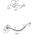
- a powder reservoir 10 of a conventional type contains a supply of flame spraying powder (not shown).
- a conduit 11 connects between the reservoir 10 and a powder metering device 12.
- the powder conduit 11 may be merely an orifice in a connecting structure between the reservoir and metering device or may in fact be a length of hose or the like through which powder is gravity fed.
- the metering device 12 has a vibrator 13 rigidly attached thereto.
- Powder carrier gas from a carrier gas source 14 flows through a gas conduit 15 to the metering device 12 where powder is entrained in the carrier gas at a controlled rate in a conventional manner.
- the entrained powder is fed through a flexible conduit 16 to a flame spray gun 17.
- the flexible conduit 16 is formed conventionally of durable, fiber-reinforced plastic material and has conventional inner and outer diameter dimensions, for example, 4.8 mm and 7.9 mm, respectively.
- Fig. 2 shows the flexible conduit 16 according to the present invention in greater detail.
- the conduit 16 is attached to the metering device 12 by means of a conventional hose connector 18, preferably made of metal such as brass or steel.
- the hose connector 18 has a tubular member 22 which is tightly fitted to one end of the conduit 16.
- Afemale threaded portion 21 cooperates with the tubular member 22 to thread onto male threaded coupler 19 which is mounted on the metering device thereby providing a coupling between the metering device 12 and the conduit 16.
- conduit 16 At the opposite end of the conduit 16 is a similar coupling member 23 which is used to couple the conduit 16 to a flame spray gun (not shown).
- a close- fitting wire coil 20 encircles the conduit 16.
- One end of coil 20 is coupled to the tubular member 22 by any suitable means which allows vibrations of the tubular member 22 to be coupled to the coiled wire 20.
- Suitable coupling means include, but are not limited to, soldering, bolting or preferably crimping the wire.
- the wire coil 20 extends along the conduit 16 a substantial distance D toward the other end of the conduit where the flame spray gun (not shown) can be connected thereto.
- the distance D is at least to, and preferably past, the lowest point of the conduit 16 while the system is in use for flame spraying. This means that the distance D is at least half the length of conduit 16, and preferably about three fourths of the length.
- the coil should be close fitting so as to assure intimate contact between the wire and the flexible conduit 16.
- Each loop of the coil may touch the next in a tightly formed coil, but it is not necessary for the loops to touch each other.
- there be a gap between each successive loop for example, equal to about from half the diameter of the flexible conduit to one diameter of the flexible conduit.
- the vibrator 13 is turned on priorto turning on the flame spray gun 17.
- the vibrations from the vibrator 13 are transmitted through the metering device 12, the threaded coupler 18, the tubular member 22 to the coil 20.
- the vibrations are then transmitted down the length of the coil 20 thereby causing the conduit 16 to vibrate.
- the vibration of the conduit 16 prevents the powder therein from clumping together even when there is no gas flow therethrough. Accordingly, powder delivery is made more uniform when the spray gun 17 is turned on.
- the sheath may be of the type of armored cable commonly used for flexible electrical conduit.
- the attachment point of the coil or other sheath may be as described or may be by a simple screw connection of an extension of the wire to another part of the powder metering device or even directly to the vibrator.
- the material of the sheath is denoted herein as "metallic", although the same need not be a metal, since the material should have metal-like elastic properties necessary for transmitting vibrations.
- a hard plastic such as acetal has such elastic properties.
- An alternative embodiment might be to couple the vibrator directly to the lowest point of the flexible conduit carrying the powder and carrier gas.
- the wire coil or other type of sheath may be covered with non-metallic flexible tube of plastic or the like which may serve to protect the sheath from damage, or conversely to protect proximate apparatus or material from any abrasive or other damaging effects that might result from contacting the sheath.
- the outer tube is loose fitting over the sheath to minimize absorption and consequent reduction of the vibrations on the sheath.
Landscapes
- Engineering & Computer Science (AREA)
- Mechanical Engineering (AREA)
- Nozzles (AREA)
Applications Claiming Priority (2)
| Application Number | Priority Date | Filing Date | Title |
|---|---|---|---|
| US513595 | 1983-07-14 | ||
| US06/513,595 US4540120A (en) | 1983-07-14 | 1983-07-14 | Powder feed system for flame spray guns |
Publications (2)
| Publication Number | Publication Date |
|---|---|
| EP0131805A1 EP0131805A1 (en) | 1985-01-23 |
| EP0131805B1 true EP0131805B1 (en) | 1987-12-02 |
Family
ID=24043915
Family Applications (1)
| Application Number | Title | Priority Date | Filing Date |
|---|---|---|---|
| EP84107424A Expired EP0131805B1 (en) | 1983-07-14 | 1984-06-27 | Powder feed system for flame spray guns |
Country Status (5)
| Country | Link |
|---|---|
| US (1) | US4540120A (https=) |
| EP (1) | EP0131805B1 (https=) |
| JP (1) | JPS6038053A (https=) |
| CA (1) | CA1211006A (https=) |
| DE (1) | DE3467861D1 (https=) |
Families Citing this family (5)
| Publication number | Priority date | Publication date | Assignee | Title |
|---|---|---|---|---|
| FR2586592B1 (fr) * | 1985-09-04 | 1988-07-15 | Sames Sa | Procede de projection d'un produit pulverulent et projecteur de produit pulverulent mettant en oeuvre un tel procede. |
| ATE83465T1 (de) * | 1988-10-04 | 1993-01-15 | Gericke Ag Maschinenfabrik | Verfahren und vorrichtung zum pneumatischen langsamfoerdern koerniger feststoffe oder dergleichen durch foerderleitungen. |
| FI114854B (fi) * | 2003-02-11 | 2005-01-14 | Liekki Oy | Menetelmä nesteen syöttämiseksi liekkiruiskutuslaitteistoon |
| US7191966B2 (en) * | 2003-08-04 | 2007-03-20 | Jeffrey David Sawczyszyn | Universal flexible powder coating tip/nozzle |
| EP2415698B1 (de) | 2010-08-05 | 2013-03-20 | Sulzer Metco AG | Zuführeinrichtung sowie Verfahren zur Zuführung eines pulverförmigen Materials von einem Vorratsbehälter zu einer Pulver verarbeitenden Einrichtung |
Family Cites Families (11)
| Publication number | Priority date | Publication date | Assignee | Title |
|---|---|---|---|---|
| US2779510A (en) * | 1954-09-27 | 1957-01-29 | Union Carbide & Carbon Corp | Vibrational dispenser for forming solid gas mixtures |
| US3048498A (en) * | 1956-03-20 | 1962-08-07 | Ransburg Electro Coating Corp | Electrostatic spray coating system |
| US3138298A (en) * | 1961-07-19 | 1964-06-23 | Metco Inc | Powder feed and metering device for flame spray guns |
| DE1278945B (de) * | 1966-02-10 | 1968-09-26 | Carrier Mfg Company | Anordnung, bestehend aus Vorratsbehaelter und Vibrationstrichter |
| US3501097A (en) * | 1966-12-29 | 1970-03-17 | Metco Inc | Powder feed device for flame spray guns |
| DE1281769B (de) * | 1966-12-30 | 1968-10-31 | Messer Griesheim Gmbh | Verfahren und Vorrichtung zur Zufuehrung eines Pulvers in den Plasmastrahl beim Plasmaspritzen |
| US3976332A (en) * | 1969-05-26 | 1976-08-24 | Metco, Inc. | Powder feed device for flame spray guns |
| US4026606A (en) * | 1975-08-21 | 1977-05-31 | Monsanto Company | Conveying lightweight plastic articles |
| DE2600546C3 (de) * | 1976-01-08 | 1978-09-21 | Buehler-Miag Gmbh, 3300 Braunschweig | Anordnung zum Abreinigen flexibler Leitungen für die pneumatische Förderung |
| DE2853106C2 (de) * | 1978-12-08 | 1987-02-05 | Maschinenfabrik Karl Brieden & Co, 4630 Bochum | Anlage zur pneumatischen Druckkesselförderung hydraulischer Baustoffe im Berg- und Tunnelbau |
| DE2946569A1 (de) * | 1979-11-19 | 1981-05-21 | MTU Motoren- und Turbinen-Union München GmbH, 8000 München | Vorrichtung zum thermischen verspritzen von metall- und keramikpulvern |
-
1983
- 1983-07-14 US US06/513,595 patent/US4540120A/en not_active Expired - Fee Related
-
1984
- 1984-05-10 CA CA000454034A patent/CA1211006A/en not_active Expired
- 1984-06-27 DE DE8484107424T patent/DE3467861D1/de not_active Expired
- 1984-06-27 EP EP84107424A patent/EP0131805B1/en not_active Expired
- 1984-07-13 JP JP59144601A patent/JPS6038053A/ja active Granted
Also Published As
| Publication number | Publication date |
|---|---|
| US4540120A (en) | 1985-09-10 |
| CA1211006A (en) | 1986-09-09 |
| JPH0526553B2 (https=) | 1993-04-16 |
| DE3467861D1 (en) | 1988-01-14 |
| EP0131805A1 (en) | 1985-01-23 |
| JPS6038053A (ja) | 1985-02-27 |
Similar Documents
| Publication | Publication Date | Title |
|---|---|---|
| US6051274A (en) | Method for conveying pulverulent material | |
| US4866240A (en) | Nozzle for plasma torch and method for introducing powder into the plasma plume of a plasma torch | |
| US5924631A (en) | Triboelectric projector, installation for projecting coating product and process for controlling such a projector | |
| DE3508132C2 (de) | Verfahren zur Zufuhr eines pulverförmigen Materials und Vorrichtung zur Durchführung des Verfahrens | |
| HU9402732D0 (en) | Nozzle of a sand blaster for dust-free blasting of plain surfaces | |
| US11446683B2 (en) | Powder conveying injector for conveying coating powder and Venturi nozzle assembly | |
| EP0131805B1 (en) | Powder feed system for flame spray guns | |
| US6217654B1 (en) | Method and equipment for powder spray coating | |
| EP0152223A2 (en) | High pressure jets | |
| CA2269979C (en) | Conveying injector | |
| US3795348A (en) | Device for delivering particulate material | |
| US4729513A (en) | Lance extension venturi sleeve | |
| EP0832695A3 (en) | An electrostratic flavouring system | |
| US7644872B2 (en) | Powder port blow-off for thermal spray processes | |
| WO2025219157A1 (en) | System and process for laser cladding | |
| EP0761577A1 (en) | Method and device for supplying and carrying powder | |
| JPH04266325A (ja) | 粉末ピツクアツプ装置 | |
| EP0042528B1 (en) | Submerged arc welding gun | |
| US11446684B2 (en) | Air-wash powder sieving apparatus for powder coating system | |
| WO2001097978A1 (en) | Nozzle apparatus and process for cleaning interior surface of pipes using same | |
| SU1049115A1 (ru) | Устройство дл нанесени покрытий из порошковых материалов в электростатическом поле | |
| US20230030578A1 (en) | Hybrid powder feed device | |
| GB1564229A (en) | Feeding devices for plasma torches and the like | |
| US4614301A (en) | Device for proportioning and feeding powder into barrel of detonation unit | |
| US20030141393A1 (en) | Electrostatic powder spray device |
Legal Events
| Date | Code | Title | Description |
|---|---|---|---|
| PUAI | Public reference made under article 153(3) epc to a published international application that has entered the european phase |
Free format text: ORIGINAL CODE: 0009012 |
|
| AK | Designated contracting states |
Designated state(s): CH DE FR GB IT LI |
|
| 17P | Request for examination filed |
Effective date: 19850521 |
|
| 17Q | First examination report despatched |
Effective date: 19860204 |
|
| GRAA | (expected) grant |
Free format text: ORIGINAL CODE: 0009210 |
|
| AK | Designated contracting states |
Kind code of ref document: B1 Designated state(s): CH DE FR GB IT LI |
|
| ITF | It: translation for a ep patent filed | ||
| REF | Corresponds to: |
Ref document number: 3467861 Country of ref document: DE Date of ref document: 19880114 |
|
| ET | Fr: translation filed | ||
| PLBE | No opposition filed within time limit |
Free format text: ORIGINAL CODE: 0009261 |
|
| STAA | Information on the status of an ep patent application or granted ep patent |
Free format text: STATUS: NO OPPOSITION FILED WITHIN TIME LIMIT |
|
| 26N | No opposition filed | ||
| ITTA | It: last paid annual fee | ||
| PGFP | Annual fee paid to national office [announced via postgrant information from national office to epo] |
Ref country code: CH Payment date: 19950511 Year of fee payment: 12 |
|
| PGFP | Annual fee paid to national office [announced via postgrant information from national office to epo] |
Ref country code: FR Payment date: 19950526 Year of fee payment: 12 Ref country code: DE Payment date: 19950526 Year of fee payment: 12 |
|
| PGFP | Annual fee paid to national office [announced via postgrant information from national office to epo] |
Ref country code: GB Payment date: 19950530 Year of fee payment: 12 |
|
| PG25 | Lapsed in a contracting state [announced via postgrant information from national office to epo] |
Ref country code: GB Effective date: 19960627 |
|
| PG25 | Lapsed in a contracting state [announced via postgrant information from national office to epo] |
Ref country code: LI Effective date: 19960630 Ref country code: CH Effective date: 19960630 |
|
| REG | Reference to a national code |
Ref country code: CH Ref legal event code: PL |
|
| GBPC | Gb: european patent ceased through non-payment of renewal fee |
Effective date: 19960627 |
|
| PG25 | Lapsed in a contracting state [announced via postgrant information from national office to epo] |
Ref country code: FR Effective date: 19970228 |
|
| PG25 | Lapsed in a contracting state [announced via postgrant information from national office to epo] |
Ref country code: DE Effective date: 19970301 |
|
| REG | Reference to a national code |
Ref country code: FR Ref legal event code: ST |