EP0130896A1 - Fahrradteilbefestigungsvorrichtung - Google Patents
Fahrradteilbefestigungsvorrichtung Download PDFInfo
- Publication number
- EP0130896A1 EP0130896A1 EP84401319A EP84401319A EP0130896A1 EP 0130896 A1 EP0130896 A1 EP 0130896A1 EP 84401319 A EP84401319 A EP 84401319A EP 84401319 A EP84401319 A EP 84401319A EP 0130896 A1 EP0130896 A1 EP 0130896A1
- Authority
- EP
- European Patent Office
- Prior art keywords
- support
- accessory
- derailleur
- cycle
- tab
- Prior art date
- Legal status (The legal status is an assumption and is not a legal conclusion. Google has not performed a legal analysis and makes no representation as to the accuracy of the status listed.)
- Granted
Links
Images


Classifications
-
- B—PERFORMING OPERATIONS; TRANSPORTING
- B62—LAND VEHICLES FOR TRAVELLING OTHERWISE THAN ON RAILS
- B62K—CYCLES; CYCLE FRAMES; CYCLE STEERING DEVICES; RIDER-OPERATED TERMINAL CONTROLS SPECIALLY ADAPTED FOR CYCLES; CYCLE AXLE SUSPENSIONS; CYCLE SIDE-CARS, FORECARS, OR THE LIKE
- B62K19/00—Cycle frames
- B62K19/30—Frame parts shaped to receive other cycle parts or accessories
- B62K19/36—Frame parts shaped to receive other cycle parts or accessories for attaching saddle pillars, e.g. adjustable during ride
-
- B—PERFORMING OPERATIONS; TRANSPORTING
- B62—LAND VEHICLES FOR TRAVELLING OTHERWISE THAN ON RAILS
- B62K—CYCLES; CYCLE FRAMES; CYCLE STEERING DEVICES; RIDER-OPERATED TERMINAL CONTROLS SPECIALLY ADAPTED FOR CYCLES; CYCLE AXLE SUSPENSIONS; CYCLE SIDE-CARS, FORECARS, OR THE LIKE
- B62K19/00—Cycle frames
- B62K19/30—Frame parts shaped to receive other cycle parts or accessories
- B62K19/38—Frame parts shaped to receive other cycle parts or accessories for attaching brake members
-
- B—PERFORMING OPERATIONS; TRANSPORTING
- B62—LAND VEHICLES FOR TRAVELLING OTHERWISE THAN ON RAILS
- B62K—CYCLES; CYCLE FRAMES; CYCLE STEERING DEVICES; RIDER-OPERATED TERMINAL CONTROLS SPECIALLY ADAPTED FOR CYCLES; CYCLE AXLE SUSPENSIONS; CYCLE SIDE-CARS, FORECARS, OR THE LIKE
- B62K19/00—Cycle frames
- B62K19/30—Frame parts shaped to receive other cycle parts or accessories
- B62K19/40—Frame parts shaped to receive other cycle parts or accessories for attaching accessories, e.g. article carriers, lamps
-
- Y—GENERAL TAGGING OF NEW TECHNOLOGICAL DEVELOPMENTS; GENERAL TAGGING OF CROSS-SECTIONAL TECHNOLOGIES SPANNING OVER SEVERAL SECTIONS OF THE IPC; TECHNICAL SUBJECTS COVERED BY FORMER USPC CROSS-REFERENCE ART COLLECTIONS [XRACs] AND DIGESTS
- Y10—TECHNICAL SUBJECTS COVERED BY FORMER USPC
- Y10T—TECHNICAL SUBJECTS COVERED BY FORMER US CLASSIFICATION
- Y10T403/00—Joints and connections
- Y10T403/30—Laterally related members connected by latch means, e.g., scaffold connectors
-
- Y—GENERAL TAGGING OF NEW TECHNOLOGICAL DEVELOPMENTS; GENERAL TAGGING OF CROSS-SECTIONAL TECHNOLOGIES SPANNING OVER SEVERAL SECTIONS OF THE IPC; TECHNICAL SUBJECTS COVERED BY FORMER USPC CROSS-REFERENCE ART COLLECTIONS [XRACs] AND DIGESTS
- Y10—TECHNICAL SUBJECTS COVERED BY FORMER USPC
- Y10T—TECHNICAL SUBJECTS COVERED BY FORMER US CLASSIFICATION
- Y10T403/00—Joints and connections
- Y10T403/71—Rod side to plate or side
- Y10T403/7182—Yoke or ring-type connector
-
- Y—GENERAL TAGGING OF NEW TECHNOLOGICAL DEVELOPMENTS; GENERAL TAGGING OF CROSS-SECTIONAL TECHNOLOGIES SPANNING OVER SEVERAL SECTIONS OF THE IPC; TECHNICAL SUBJECTS COVERED BY FORMER USPC CROSS-REFERENCE ART COLLECTIONS [XRACs] AND DIGESTS
- Y10—TECHNICAL SUBJECTS COVERED BY FORMER USPC
- Y10T—TECHNICAL SUBJECTS COVERED BY FORMER US CLASSIFICATION
- Y10T74/00—Machine element or mechanism
- Y10T74/20—Control lever and linkage systems
- Y10T74/20207—Multiple controlling elements for single controlled element
- Y10T74/20256—Steering and controls assemblies
- Y10T74/20268—Reciprocating control elements
- Y10T74/2028—Handle bar type
- Y10T74/20287—Flexible control element
-
- Y—GENERAL TAGGING OF NEW TECHNOLOGICAL DEVELOPMENTS; GENERAL TAGGING OF CROSS-SECTIONAL TECHNOLOGIES SPANNING OVER SEVERAL SECTIONS OF THE IPC; TECHNICAL SUBJECTS COVERED BY FORMER USPC CROSS-REFERENCE ART COLLECTIONS [XRACs] AND DIGESTS
- Y10—TECHNICAL SUBJECTS COVERED BY FORMER USPC
- Y10T—TECHNICAL SUBJECTS COVERED BY FORMER US CLASSIFICATION
- Y10T74/00—Machine element or mechanism
- Y10T74/20—Control lever and linkage systems
- Y10T74/20396—Hand operated
- Y10T74/20402—Flexible transmitter [e.g., Bowden cable]
- Y10T74/2042—Flexible transmitter [e.g., Bowden cable] and hand operator
- Y10T74/20438—Single rotatable lever [e.g., for bicycle brake or derailleur]
Definitions
- the present invention relates to the mounting and fixing of cycle accessories, such as, for example, front and rear derailleurs, actuating levers of these derailleurs, brakes, etc.
- Document DE-A-936 795 describes a motor vehicle, the fuel tank of which is fixed astride a tube of the frame.
- This fixing is carried out, on the one hand, by means of a first lug carried by the reservoir and which engages in a stirrup carried by the tube and, on the other hand, by means of a second lug secured to the reservoir and which is clamped on the tube by a collar.
- the fixing is in fact carried out by the collar, the first tab and the stirrup having only a function of retaining the upper part of the tank.
- Such a fixing device therefore remains complex and does not provide an element of solution, in particular when the accessory plays an active role and supports efforts, during the use of the cycle, which is not the case. of a tank.
- Document CH-A-427,539 describes, in one of its variants, the mounting of a crutch on a cycle, produced by means of two complementary parts, in the form of a trunk, cone or pyramid, carried respectively by the frame and the kickstand itself.
- the blocking of the two parts is not positive so that this type of fixing is not suitable in the case of an accessory subjected, during use, to stresses.
- the problem that the invention proposes to solve is as follows: providing a device for attaching cycle accessories, which is simpler than existing devices and which makes it possible to simplify assembly operations, in particular by authorizing the supply of the accessory ready to be mounted.
- the invention therefore relates to a device for fixing an accessory on a cycle, characterized in that it comprises a support on which said accessory is mounted, this support and the part of the cycle on which it must be fixed comprising two complementary male and female parts respectively, arranged so as to be made integral by wedging, the arrangement being such that, when 'a force is exerted on the accessory, in use, this force tends to increase the wedging between the male part and the female part.
- these two levers are carried by a support 4 comprising a central portion 5 curved to match the shape of the tube constituting the frame, extended by two lateral branches 6 delimiting on the one hand, a housing 7, for example of shape square, for receiving the head 8a of a stud 8 for fastening of the handle, and secondly, an orifice 9 for the passage of the shank 8b of the pad.
- a support 4 comprising a central portion 5 curved to match the shape of the tube constituting the frame, extended by two lateral branches 6 delimiting on the one hand, a housing 7, for example of shape square, for receiving the head 8a of a stud 8 for fastening of the handle, and secondly, an orifice 9 for the passage of the shank 8b of the pad.
- Each lever is fixed to the corresponding stud by means of a screw 10.
- the support for the two levers comprises, integrally, a tab 11 directed downwards, which also follows the shape of the tube and the two sides 12, 13 of which converge slightly towards each other by a few degrees, for example 5 ° each with respect to the direction parallel to the axis of the tube 1.
- the trigger guard is preferably open at its lower part to allow the lower part of the tab 11 to protrude and it has two side walls 15, 16 which also converge, at approximately the same angle as that of the sides 12, 13 of the tab, as can be seen in fig. 3.
- a simple lever 20 for actuating a front or rear derailleur is shown.
- This lever is carried by a support 21 in which is formed by a punctured tab 22 which corresponds in its function to the tab 11 of fig. 1 to 3.
- This tab has a curvature corresponding to that of the tube on which it is fixed and has two lateral edges 23, 24 which converge slightly towards each other, for example at the same angle of twice 5 ° as in the previous embodiment.
- this tab is cut so as to leave on the support a central portion 25 of sufficiently large area on which is soldered or otherwise fixed a mounting stud 26 for the handle.
- the cut thus formed in the support has a general shape in M.
- a bridge 28 intended to delimit with the tube the housing in which comes to engage and jam the tab 22; the side walls of this trigger guard converge at an angle roughly equal to that formed between the edges of the tab 22.
- the traction exerted by the cable, in use, and which is of the order of 20 kg requests the support in a direction which tends to increase jamming, thus ensuring a very good support on the frame.
- FIG. 6 shows the mounting of a rear brake 30.
- This brake is fixed on a support 31 which has at its front part a fixing lug 32 of planar shape and whose two longitudinal edges 33, 34 converge as in the case of the examples previous.
- This tab is intended to come to engage in a housing 35 of corresponding shape, that is to say of which the two longitudinal sides 36, 37 are also convergent and which is formed in a spacer 38, possibly reinforced, extending between two shrouds 39, 40 of the frame.
- the force supported by the brake in use and transmitted to its support has the effect of tending to further engage the tab 32 in its housing and therefore to increase the wedging between these two elements. The brake is therefore unlikely to be released.
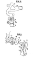
- a device from my level of a front derailleur 50 or bottom derailleur comprises, conventionally, a yoke 51 connected to a support 52 by an articulation mechanism which will not be described in detail and which may be of the type constituted by a deformable parallelogram.
- the support 52 which can be seen more clearly in FIG. 8 has a curved shape, with a profile corresponding to that of the tube 53 on which it is fixed.
- This support is extended downwards by a tab 54 which is entirely similar to that of the support shown in FIGS. 1 to 3. This tab therefore has two sides 55, 56 which converge slightly towards one another.
- the trigger guard has two slightly converging sides, for example at an angle of 5 ° relative to the direction parallel to the axis of the tube. Again the traction exerted by the actuator cable of the derailleur helps maintain the support relative to the frame, despite the absence of a collar.
- FIG. 9 shows the mounting of a rear derailleur 60.
- This derailleur is carried by a support plate 61 itself fixed on a frame lug 62.
- the support plate has a slot 63a intended to come approximately in coincidence with the slot 63b formed in the frame tab and in which the axis of the rear wheel is fixed.
- this support plate has a tab 64 extending upwards at approximately right angles to the direction of the slot 63a.
- This lug is intended to be received in a housing delimited by the frame lug and a trigger guard 65 brazed on this lug or else made by a punctured.
- this trigger guard preferably delimits a housing of convergent shape and the tab has a corresponding shape so as to achieve a certain wedging of the support plate relative to the frame tab.
- Figs. 10 and 11 shows another embodiment of a fixing of a derailleur 70 on a frame tab 71.
- This derailleur comprises an upper part 72 constituting one of the sides of a parallelogram or of an articulated quadrilateral, on which are articulated the two longitudinal sides of this parallelogram or this quadrilateral.
- the part 72 has a bottom 72a and two side walls 72. It is between these two side walls that the two longitudinal sides of the parallelogram are articulated.
- the bottom 72a has a notch 73 open at its upper part, which is intended to come to engage on the two flat faces 74 of the rod of a fixing member 75.
- first stop washer 77 Between the head 76 of this fixing member and the tab frame are arranged a first stop washer 77, a second washer 78 delimiting a stop for the sheath of the actuating cable, and an elastic washer 79.
- the fixing member After mounting the fixing member is preferably riveted on the tab of frame, the end 80 of the rod of this fixing member then being opened out to constitute the head of the rivet.
- wedging can be achieved between the edges of the notch 73 and the flat faces 74 of the fixing member 75.
- the derailleur is then mounted by simple engagement on the fixing member 75, this mounting being effected by sufficiently compressing the elastic washer 79, so that the derailleur is correctly fixed.
- the means of wedging between the two male and female parts may include notches and / or snap-in means to improve the grip.
Applications Claiming Priority (2)
| Application Number | Priority Date | Filing Date | Title |
|---|---|---|---|
| FR8311018A FR2548127B1 (fr) | 1983-07-01 | 1983-07-01 | Dispositif de fixation d'un accessoire sur un cycle |
| FR8311018 | 1983-07-01 |
Publications (2)
| Publication Number | Publication Date |
|---|---|
| EP0130896A1 true EP0130896A1 (de) | 1985-01-09 |
| EP0130896B1 EP0130896B1 (de) | 1988-04-27 |
Family
ID=9290429
Family Applications (1)
| Application Number | Title | Priority Date | Filing Date |
|---|---|---|---|
| EP84401319A Expired EP0130896B1 (de) | 1983-07-01 | 1984-06-22 | Fahrradteilbefestigungsvorrichtung |
Country Status (5)
| Country | Link |
|---|---|
| US (1) | US4624151A (de) |
| EP (1) | EP0130896B1 (de) |
| JP (1) | JPS60185686A (de) |
| DE (1) | DE3470719D1 (de) |
| FR (1) | FR2548127B1 (de) |
Cited By (3)
| Publication number | Priority date | Publication date | Assignee | Title |
|---|---|---|---|---|
| WO1992004549A1 (en) * | 1990-09-12 | 1992-03-19 | Norman Leslie Matthews | A fastener |
| WO1994006670A2 (en) * | 1992-09-18 | 1994-03-31 | Softride, Inc. | Modular composite bicycle frame |
| US5456481A (en) * | 1989-04-07 | 1995-10-10 | Softride, Inc. | Modular composite bicycle frame |
Families Citing this family (10)
| Publication number | Priority date | Publication date | Assignee | Title |
|---|---|---|---|---|
| US4790207A (en) * | 1986-11-14 | 1988-12-13 | Huffy Corporation | Bicycle control lever mounting system |
| US4905536A (en) * | 1987-12-21 | 1990-03-06 | Honda Giken Kogyo Kabushiki Kaisha | Power transmission change-over device for small sized vehicles |
| JP2557292Y2 (ja) * | 1991-06-12 | 1997-12-10 | 株式会社リズム | 荷重応動型ブレーキ液圧制御弁の組立体 |
| US5919106A (en) * | 1997-04-30 | 1999-07-06 | Shimano, Inc. | Quick release derailleur |
| US6293883B1 (en) | 1998-09-10 | 2001-09-25 | Shimano, Inc. | Quick release derailleur |
| US20080051237A1 (en) * | 2006-08-24 | 2008-02-28 | Shimano Inc. | Bicycle rear derailleur |
| US8307954B2 (en) * | 2007-09-05 | 2012-11-13 | Kimori Limited | Caliper brake attachment tool for rear wheel of bicycle |
| JP4834052B2 (ja) * | 2008-11-17 | 2011-12-07 | 有限会社ワダノブテックス | トーションレース |
| AU350293S (en) * | 2013-01-11 | 2013-08-22 | Mucky Nutz Ltd | Fenders |
| AU350292S (en) * | 2013-01-11 | 2013-08-22 | Mucky Nutz Ltd | Fenders |
Citations (3)
| Publication number | Priority date | Publication date | Assignee | Title |
|---|---|---|---|---|
| DE936795C (de) * | 1954-07-16 | 1955-12-22 | Fritz Roth K G | Befestigung von sattelfoermigen Brennstoffbehaeltern auf dem Rahmen von Motorraedern |
| FR1284252A (fr) * | 1961-03-08 | 1962-02-09 | Dispositif d'attache des changements de vitesse sur la patte du cadre des cycles | |
| CH427539A (de) * | 1963-10-07 | 1966-12-31 | Pletscher Geb | Befestigung von Fahrradteilen am Fahrradrahmen |
Family Cites Families (10)
| Publication number | Priority date | Publication date | Assignee | Title |
|---|---|---|---|---|
| US584738A (en) * | 1897-06-15 | Harrow-tooth fastener | ||
| US676984A (en) * | 1900-07-09 | 1901-06-25 | Johann Hofbauer | Means for attaching tools to their handles. |
| FR403980A (fr) * | 1909-06-12 | 1909-11-19 | William James Welch | Perfectionnements aux dispositifs pour le montage des selles de bicyclettes |
| US1094413A (en) * | 1911-11-21 | 1914-04-28 | Gilbert H Bagley | Whip-socket. |
| US1099764A (en) * | 1914-02-06 | 1914-06-09 | Abraham Polansky | Bed-joint. |
| US1345209A (en) * | 1920-01-09 | 1920-06-29 | Charles A Martin | Cultivator-tooth |
| US3426614A (en) * | 1967-01-09 | 1969-02-11 | Schwinn Bicycle Co | Twin control lever assembly |
| US3870259A (en) * | 1973-08-08 | 1975-03-11 | Lester A Reynolds | Fishing rod holder |
| US4157075A (en) * | 1977-10-11 | 1979-06-05 | John Kirvutza | Bicycle signal device |
| JPS6019035Y2 (ja) * | 1980-06-27 | 1985-06-08 | 株式会社シマノ | 自転車用変速操作装置 |
-
1983
- 1983-07-01 FR FR8311018A patent/FR2548127B1/fr not_active Expired
-
1984
- 1984-06-22 DE DE8484401319T patent/DE3470719D1/de not_active Expired
- 1984-06-22 EP EP84401319A patent/EP0130896B1/de not_active Expired
- 1984-06-26 US US06/624,711 patent/US4624151A/en not_active Expired - Fee Related
- 1984-07-02 JP JP59137854A patent/JPS60185686A/ja active Pending
Patent Citations (3)
| Publication number | Priority date | Publication date | Assignee | Title |
|---|---|---|---|---|
| DE936795C (de) * | 1954-07-16 | 1955-12-22 | Fritz Roth K G | Befestigung von sattelfoermigen Brennstoffbehaeltern auf dem Rahmen von Motorraedern |
| FR1284252A (fr) * | 1961-03-08 | 1962-02-09 | Dispositif d'attache des changements de vitesse sur la patte du cadre des cycles | |
| CH427539A (de) * | 1963-10-07 | 1966-12-31 | Pletscher Geb | Befestigung von Fahrradteilen am Fahrradrahmen |
Cited By (5)
| Publication number | Priority date | Publication date | Assignee | Title |
|---|---|---|---|---|
| US5456481A (en) * | 1989-04-07 | 1995-10-10 | Softride, Inc. | Modular composite bicycle frame |
| WO1992004549A1 (en) * | 1990-09-12 | 1992-03-19 | Norman Leslie Matthews | A fastener |
| US5494368A (en) * | 1990-09-12 | 1996-02-27 | Matthews; Norman L. | Fastener |
| WO1994006670A2 (en) * | 1992-09-18 | 1994-03-31 | Softride, Inc. | Modular composite bicycle frame |
| WO1994006670A3 (en) * | 1992-09-18 | 1994-06-23 | Allsop Inc | Modular composite bicycle frame |
Also Published As
| Publication number | Publication date |
|---|---|
| FR2548127A1 (fr) | 1985-01-04 |
| DE3470719D1 (en) | 1988-06-01 |
| EP0130896B1 (de) | 1988-04-27 |
| FR2548127B1 (fr) | 1988-08-12 |
| US4624151A (en) | 1986-11-25 |
| JPS60185686A (ja) | 1985-09-21 |
Similar Documents
| Publication | Publication Date | Title |
|---|---|---|
| EP0130896B1 (de) | Fahrradteilbefestigungsvorrichtung | |
| US6470767B2 (en) | Cable connecting apparatus for bicycle component | |
| FR2692222A3 (fr) | Pédale à fixation rapide, sans cale-pied, avec deux côtes pouvant se mettre en prise avec un dispositif de fixation. | |
| EP1787878B1 (de) | Befestigungsvorrichtung, insbesondere einer Betätigungsstange eines Bremskraftverstärkers an ein Bremspedal eines Kraftfahrzeuges | |
| EP1142781B1 (de) | Fahrradpedal mit automatischem Fixierungselement | |
| EP0739596B1 (de) | Einstellbarer Verschluss für Schuhe | |
| EP1723005B1 (de) | Am heck eines kraftfahrzeugs angebrachter lastträger | |
| FR2582611A1 (fr) | Dispositif de commande de frein | |
| EP0216717B1 (de) | Klemmzange mit selbsteinstellenden Backen | |
| EP0424204B1 (de) | Verbindung zwischen Türgriff und Betätigungsstange eines Kfz-Türschlosses | |
| EP0999368B1 (de) | Befestigungsklammer, insbesondere für Handleuchte | |
| EP0486341A1 (de) | Mechanisch betätigbare Trommelbremse | |
| FR2551017A1 (fr) | Frein a machoires pour bicyclettes | |
| EP1531519A1 (de) | Elektrische Anschlussklemme und elektrisches Schutzgerät mit einer solchen Klemme | |
| CA1064411A (fr) | Freins a machoires pour cycles et similaires | |
| EP0326481A1 (de) | Zangenförmige Mutter und damit erfolgter Zusammenbau | |
| EP0199628A1 (de) | Sicherheitssteigbügel für den Reitsport | |
| FR2550855A1 (fr) | Mecanisme de percussion a chien interieur pour fusils | |
| EP0199623B1 (de) | Betätigungsgestänge für Ein- und Ausrückvorrichtung, z.B. für Kupplungen, insbesondere für Kraftfahrzeuge | |
| EP0146444B1 (de) | Verankerung eines Verstrebungselementes, welches eine Einrichtung zur automatischen Regelung für ein Bremsbackensegment aufweist | |
| EP0934870A2 (de) | Befestigungsklammer für ein Fahrradschutzblech mit einer Stützstange | |
| EP0965518B1 (de) | Fahrradfelgenbremse | |
| WO2002008049A1 (fr) | Remorque pour un vehicule deux-roues | |
| FR2536714A1 (fr) | Mecanisme de commande de frein a main | |
| EP0132177B1 (de) | Montier- und Befestigungsvorrichtung für eine Bremse an einem Fahrrad |
Legal Events
| Date | Code | Title | Description |
|---|---|---|---|
| PUAI | Public reference made under article 153(3) epc to a published international application that has entered the european phase |
Free format text: ORIGINAL CODE: 0009012 |
|
| AK | Designated contracting states |
Designated state(s): BE DE GB IT LU NL |
|
| 17P | Request for examination filed |
Effective date: 19841115 |
|
| 17Q | First examination report despatched |
Effective date: 19860219 |
|
| R17C | First examination report despatched (corrected) |
Effective date: 19860819 |
|
| RAP1 | Party data changed (applicant data changed or rights of an application transferred) |
Owner name: SACHS-HURET S.A. |
|
| GRAA | (expected) grant |
Free format text: ORIGINAL CODE: 0009210 |
|
| AK | Designated contracting states |
Kind code of ref document: B1 Designated state(s): BE DE GB IT LU NL |
|
| ITF | It: translation for a ep patent filed |
Owner name: JACOBACCI & PERANI S.P.A. |
|
| GBT | Gb: translation of ep patent filed (gb section 77(6)(a)/1977) | ||
| REF | Corresponds to: |
Ref document number: 3470719 Country of ref document: DE Date of ref document: 19880601 |
|
| PG25 | Lapsed in a contracting state [announced via postgrant information from national office to epo] |
Ref country code: LU Free format text: LAPSE BECAUSE OF NON-PAYMENT OF DUE FEES Effective date: 19880630 |
|
| PLBE | No opposition filed within time limit |
Free format text: ORIGINAL CODE: 0009261 |
|
| STAA | Information on the status of an ep patent application or granted ep patent |
Free format text: STATUS: NO OPPOSITION FILED WITHIN TIME LIMIT |
|
| 26N | No opposition filed | ||
| PGFP | Annual fee paid to national office [announced via postgrant information from national office to epo] |
Ref country code: LU Payment date: 19900530 Year of fee payment: 7 |
|
| PGFP | Annual fee paid to national office [announced via postgrant information from national office to epo] |
Ref country code: GB Payment date: 19900618 Year of fee payment: 7 |
|
| PGFP | Annual fee paid to national office [announced via postgrant information from national office to epo] |
Ref country code: DE Payment date: 19900622 Year of fee payment: 7 |
|
| ITTA | It: last paid annual fee | ||
| PGFP | Annual fee paid to national office [announced via postgrant information from national office to epo] |
Ref country code: NL Payment date: 19900630 Year of fee payment: 7 |
|
| PGFP | Annual fee paid to national office [announced via postgrant information from national office to epo] |
Ref country code: BE Payment date: 19900712 Year of fee payment: 7 |
|
| PG25 | Lapsed in a contracting state [announced via postgrant information from national office to epo] |
Ref country code: GB Effective date: 19910622 |
|
| PG25 | Lapsed in a contracting state [announced via postgrant information from national office to epo] |
Ref country code: BE Effective date: 19910630 |
|
| BERE | Be: lapsed |
Owner name: S.A. SACHS-HURET Effective date: 19910630 |
|
| PG25 | Lapsed in a contracting state [announced via postgrant information from national office to epo] |
Ref country code: NL Effective date: 19920101 |
|
| NLV4 | Nl: lapsed or anulled due to non-payment of the annual fee | ||
| GBPC | Gb: european patent ceased through non-payment of renewal fee | ||
| PG25 | Lapsed in a contracting state [announced via postgrant information from national office to epo] |
Ref country code: DE Effective date: 19920401 |