EP0130510A1 - Apparatus for making a reconstituted tobacco sheet - Google Patents
Apparatus for making a reconstituted tobacco sheet Download PDFInfo
- Publication number
- EP0130510A1 EP0130510A1 EP84107215A EP84107215A EP0130510A1 EP 0130510 A1 EP0130510 A1 EP 0130510A1 EP 84107215 A EP84107215 A EP 84107215A EP 84107215 A EP84107215 A EP 84107215A EP 0130510 A1 EP0130510 A1 EP 0130510A1
- Authority
- EP
- European Patent Office
- Prior art keywords
- suspension
- edge
- feed line
- displacement body
- sieves
- Prior art date
- Legal status (The legal status is an assumption and is not a legal conclusion. Google has not performed a legal analysis and makes no representation as to the accuracy of the status listed.)
- Granted
Links
Images


Classifications
-
- A—HUMAN NECESSITIES
- A24—TOBACCO; CIGARS; CIGARETTES; SIMULATED SMOKING DEVICES; SMOKERS' REQUISITES
- A24B—MANUFACTURE OR PREPARATION OF TOBACCO FOR SMOKING OR CHEWING; TOBACCO; SNUFF
- A24B3/00—Preparing tobacco in the factory
- A24B3/14—Forming reconstituted tobacco products, e.g. wrapper materials, sheets, imitation leaves, rods, cakes; Forms of such products
Definitions
- the invention relates to a device for producing a reconstituted tobacco film from an aqueous suspension of finely ground particles, in particular tobacco waste, which is fed to a double sheet former, two sieves converging approximately in a V shape being provided in their sheet formation areas, between which a tapering displacement body is arranged , and wherein to deposit partial films from the suspension suction boxes are arranged under the sieves.
- the object of the invention is to provide the double sheet former of a device for the production of reconstituted tobacco foils with a headbox which feeds the suspension of the two partial foils in the same amount and with the same bubble-free consistency.
- the invention solves this problem in that the top of the displacer is designed as a trough, which is delimited by edge sills with a horizontal upper edge, and in that the suspension is fed into this trough.
- the supplied suspension can initially calm down on the trough-shaped upper side of the displacement body and only then flows off completely uniformly to the sheet formation zones. It is particularly advantageous if the feed line for the suspension opens into the tub within the liquid supply. In order to keep turbulence low, it is advisable to design the feed line in a manner known per se as a step diffuser with a diameter widening in the flow direction. The flow is even more even if the pipes of the feed line start from a common horizontal pipe string which is arranged inside the displacer. The latter measure also makes optimal use of the space available in the displacement body.
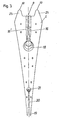
- the device shown in Fig. 1 is used to process an aqueous suspension of finely ground tobacco waste into a film.
- the suspension as shown in F ig. 2-4 is shown in more detail, fed to the top of a displacement body 1, which largely fills the gap-shaped space between the rotating sieves 3 and 4.
- the suspension passes through an acceleration zone 13 and a subsequent calming zone 17 into the sheet formation area, which is characterized by the arrangement of suction boxes 2.
- the screens are brought together in the sheet formation area via the suction zones of the suction boxes, which are always filled with tobacco extract.
- Extract is drawn off through the sieves by means of several suction zones, each of which can be set separately, whereby progressively initially coarser, later finer fiber parts are progressively retained on the sieves and thus form a sheet.
- suction zones each of which can be set separately, whereby progressively initially coarser, later finer fiber parts are progressively retained on the sieves and thus form a sheet.
- the twin-wire barrel is sealed in the vertical direction by a specially designed labyrinth seal 5 to which a low variable vacuum is connected.
- the double track enclosed between two screens runs over three alternately arranged suction cups 6.
- the vertical dewatering area is closed off by an S-shaped guide via suction rolls 7.
- the finished, but still 75% moisture-containing film 22 is first sucked in the area of the pick-up roller 8 to enable the separation of the screen 3, and then removed from the screen 4, and reaches a final moisture content of 13 to 13 ° C for drying 15% in the dryer not of interest here.
- the suspension is fed to the sheet formation zones.
- diffusers which widen in steps are used as the feed line 16. These are arranged in large numbers one after the other normal to the drawing level. From the feed lines 16, the suspension passes into a tub 10 9 forming the upper side of the displacer 1, care being taken that the upper edge / the edge thresholds 23 is higher than the lower edge of the feed line 16, so that the feed line of the suspension is always below the Liquid level 11 takes place.
- the edge thresholds 23 form a weir, via which the suspension flows along the inclined surfaces 12 into the acceleration zone 13 which tapers downwards, from which it reaches a calming zone 17 with a constant cross section.
- an overflow 15 is provided which limits the height of the liquid level.
- the outflow of the suspension from the area above the displacer 1 can be controlled by limiting plates 14, the holder of which is adjustable in height, so that an arbitrarily small gap can be produced between the lower edge of the limiting surface 14 and the upper edge 10 of the edge sleepers 23.
- an embodiment of the displacement body 1 is shown, which is characterized by a particularly gentle supply of the suspension to the tub 9 delimited by the edge sleepers 23.
- the supply of the suspension is served here by a stepwise narrowing horizontal pipe string 18 which is arranged in the interior of the displacement body and from which step diffusers 16, 16 'branch off with a cross section which widens upwards.
- a further, gradually narrowing pipe string 21 is provided, to which step-down diffusers 20 which widen downward are connected. These open into a continuous groove 19 in the area in which the two individual foils are connected to form the double sheet can be traced back to the film in formation, where it already has a sufficiently dense consistency to hold even finer solid particles like a filter.
Abstract
Beschrieben wird eine Einrichtung zur Herstellung einer rekonstituierten Tabakfolie aus einer einem Doppelblattbildner zugeleiteten wässerigen Suspension feingemahlenerTabakabfälle, wobei zwei in ihren Blattbildungsbereichen etwa V-förmig zusammenlaufende Siebe vorgesehen sind, zwischen denen ein sich nach unten verjüngender Verdrängungskörper angeordnet ist. Die Oberseite des Verdrängungskörpers (1) ist als Wanne (9) ausgebildet, in welche die Zuleitung (16) für die Suspension mündet.
Description
Die Erfindung bezieht sich auf eine Einrichtung zur Herstellung einer rekonstituierten Tabakfolie aus einer einem Doppelblattbildner zugeleiteten wässerigen Suspension feingemahlener Teilchen, insbesondere von Tabakabfällen, wobei zwei in ihren Blattbildungsbereichen etwa V-förmig zusammenlaufende Siebe vorgesehen sind, zwischen denen ein sich nach unten verjüngender Verdrängungskörper angeordnet ist, und wobei zur Niederschlagung von Teilfolien aus der Suspension Saugkästen unter den Sieben angeordnet sind.The invention relates to a device for producing a reconstituted tobacco film from an aqueous suspension of finely ground particles, in particular tobacco waste, which is fed to a double sheet former, two sieves converging approximately in a V shape being provided in their sheet formation areas, between which a tapering displacement body is arranged , and wherein to deposit partial films from the suspension suction boxes are arranged under the sieves.
Die Verwendung eines Doppelblattbildners zur Herstellung einer rekonstituierten Tabakfolie wurde erstmals in AT-PS 335 327 beschrieben. Beim Übergang von einer Produktion im Labormaßstab zur industriellen Herstellung ergab sich dabei zunächst das Problem, daß der auf den Sieben liegende Flüssigkeitsvorrat zur Entmischung neigte und zu blattbildungstechnischen Problemen führte. Diese Situation konnte dadurch verbessert werden, daß zwischen die Blattbildungsbereiche der Siebe ein Verdrängungskörper in Gestalt eines hohlen oder ausgeschäumten Behälters eingebracht wurde, der den Flüssigkeitsvorrat weitgehend reduzierte. Die Siebbereiche, in denen die Teilfolien des Doppelblattes gebildet werden, sind damit völlig voneinander getrennt, weshalb es durchaus sinnvoll schien, die zur Blattbildung dienende Suspension diesen Bereichen über gesonderte, jeweils in den Spalt zwischen Verdrängungskörper und Sieb mündende Diffusoren zuzuleiten. Allerdings zeigte sich, daß auf diese Weise die notwendige Gleichartigkeit der beiden Teilfolien nicht garantiert war und überdies durch die Einleitung der Suspension in den engen Spalt zwischen Verdrängungskörper und Sieb Luft in den Blattbildungsbereich gelangte.The use of a double sheet former for producing a reconstituted tobacco film was first described in AT-PS 335 327. When transitioning from production on a laboratory scale to industrial production, the problem initially arose that the liquid supply lying on the sieve tended to segregate and lead to problems in sheet formation. This situation could be improved by inserting a displacement body in the form of a hollow or foamed container between the sheet formation areas of the screens, which largely reduced the liquid supply. The screen areas in which the partial sheets of the double sheet are formed are thus completely separate from one another, which is why it seemed perfectly sensible to feed the suspension used for sheet formation to these areas via separate diffusers, each opening into the gap between the displacer and the screen. However, it was found that the necessary uniformity of the two partial films was not guaranteed in this way and, moreover, air was introduced into the sheet formation area through the introduction of the suspension into the narrow gap between the displacer and the sieve.
Aufgabe der Erfindung ist es demgegenüber, den Doppelblattbildner einer Einrichtung zur Herstellung von rekonstituierten Tabakfolien mit einem Stoffauflauf zu versehen, der den Blattbildungszonen beider Teilfolien die Suspension in gleicher Menge und gleicher blasenfreier Konsistenz zuführt. Die Erfindung löst die gestellte Aufgabe dadurch, daß die Oberseite des Verdrängungskörpers als Wanne, die durch Randschwellen mit horizontaler Oberkante begrenzt ist, ausgebildet ist, und daß die Zuleitung der Suspension in diese Wanne erfolgt.In contrast, the object of the invention is to provide the double sheet former of a device for the production of reconstituted tobacco foils with a headbox which feeds the suspension of the two partial foils in the same amount and with the same bubble-free consistency. The invention solves this problem in that the top of the displacer is designed as a trough, which is delimited by edge sills with a horizontal upper edge, and in that the suspension is fed into this trough.
Die zugeführte Suspension kann sich bei einer derartigen Konstruktion auf der wannenförmigen Oberseite des Verdrängungskörpers zunächst beruhigen und fließt erst anschließend völlig gleichmäßig zu den Blattbildungszonen ab. Besonders günstig ist es dabei, wenn die Zuleitung für die Suspension innerhalb des Flüssigkeitsvorrates in der Wanne mündet. Um Turbulenzen gering zu halten, empfiehlt es sich, die Zuleitung in an sich bekannter Weise als Stufendiffusor mit sich in Strömungsrichtung erweiterndem Durchmesser auszugestalten. Noch gleichmäßiger verläuft die Strömung, wenn die Rohre der Zuleitung von einem gemeinsamen horizontalen Rohrstrang ausgehen, der im Inneren des Verdrängungskörpers angeordnet ist. Durch letztere Maßnahme wird überdies der im Verdrängungskörper zur Verfügung stehende Raum optimal genützt.In the case of such a construction, the supplied suspension can initially calm down on the trough-shaped upper side of the displacement body and only then flows off completely uniformly to the sheet formation zones. It is particularly advantageous if the feed line for the suspension opens into the tub within the liquid supply. In order to keep turbulence low, it is advisable to design the feed line in a manner known per se as a step diffuser with a diameter widening in the flow direction. The flow is even more even if the pipes of the feed line start from a common horizontal pipe string which is arranged inside the displacer. The latter measure also makes optimal use of the space available in the displacement body.
Der Abfluß aus dieser Wanne erfolgt im allgemeinen entsprechend der jeweils zugeführten Menge, doch kann das Abströmen zu großer Flüssigkeitsmengen zu den Blattbildungssieben durch verstellbare Begrenzungsbleche verhindert werden.The outflow from this trough generally takes place in accordance with the quantity supplied in each case, but the outflow of excessive amounts of liquid to the sheet-forming sieves can be prevented by means of adjustable limiting plates.
Es empfiehlt sich, den oberen Rand des Verdrängungskörpers in Richtung zu den Sieben abzuschrägen, damit die über die Randschwellen abströmende Flüssigkeit zunächst einen sich nach unten stark verjüngenden Beschleunigungsbereich durchlaufen muß, bevor sie in eine dem Blattbildungsbereich vorgeschaltete Beruhigungszone konstanten Querschnitts gelangt. In der Beschleunigungszone findet erfahrungsgemäß eine Durchmischung und Homogenisierung der Suspension statt, welche bis in den Blattbildungsbereich erhalten bleibt.We recommend the top of the displacement beveled body towards the sieves, so that the liquid flowing out over the edge thresholds must first pass through a rapidly tapering acceleration region before it reaches a calming zone of constant cross section upstream of the sheet formation region. Experience has shown that mixing and homogenization of the suspension takes place in the acceleration zone, which is maintained right up to the sheet formation area.
Weitere Einzelheiten der Erfindung werden anschließend anhand der Zeichnung erläutert. In dieser stellt
- Fig. 1 schematisch einen Querschnitt durch einen Doppelblattbildner dar;
- Fig. 2 zeigt in Vergrößerung den oberen Bereich des Blattbildners mit dem erfindungsgemäßen, in Fig. 1 nicht dargestellten Stoffauflauf;
- Fig. 3 zeigt eine abgeänderte Ausführung des Verdrängungskörpers,
- Fig. 4 die zugehörige Seitenansicht.
- Fig. 1 shows schematically a cross section through a double sheet former;
- Fig. 2 shows an enlargement of the upper area of the sheet former with the inventive headbox, not shown in Fig. 1;
- 3 shows a modified version of the displacement body,
- Fig. 4 shows the associated side view.
Die in Fig. 1 dargestellte Einrichtung dient dazu, eine wässerige Suspension feingemahlener Tabakabfälle zu einer Folie zu verarbeiten. Hiezu wird die Suspension, wie in Fig. 2-4 näher dargestellt ist, an der Oberseite eines Verdrängungskörpers 1 zugeführt, welcher den spaltförmigen Zwischenraum zwischen den umlaufenden Sieben 3 und 4 weitgehend ausfüllt. Die Suspension gelangt über eine Beschleunigungszone 13 und eine anschließende Beruhigungszone 17 in den Blattbildungsbereich, der durch die Anordnung von Saugkästen 2 gekennzeichnet ist.The device shown in Fig. 1 is used to process an aqueous suspension of finely ground tobacco waste into a film. For this purpose, the suspension, as shown in F ig. 2-4 is shown in more detail, fed to the top of a
Die Siebe werden im Blattbildungsbereich über die stets mit Tabakextrakt gefüllten Saugzonen der Saugkästen zusammengeführt.The screens are brought together in the sheet formation area via the suction zones of the suction boxes, which are always filled with tobacco extract.
Durch mehrere, jeweils gesondert einstellbare Saugzonen wird Extrakt durch die Siebe abgezogen, wodurch auf den Sieben fortschreitend zunächst gröbere, später feinere Faserteile zurückgehalten werden und so ein Blatt bilden. Bei der Zusammenführung beider Halbblätter vereinigen sich diese untrennbar.Extract is drawn off through the sieves by means of several suction zones, each of which can be set separately, whereby progressively initially coarser, later finer fiber parts are progressively retained on the sieves and thus form a sheet. When the two half-sheets are brought together, they merge inseparably.
Die Abdichtung des Doppelsieblaufes in vertikaler Richtung übernimmt eine speziell konstruierte Labyrinthdichtung 5 , an die ein niedriges variables Vakuum angeschlossen ist. Zur weiteren Entwässerung läuft die zwischen zwei Sieben eingeschlossene Doppelbahn über drei alternierend angeordnete Bogensauger 6. Der vertikale Entwässerungsbereich wird durch S-förmige Führung über Saugwalzen 7 abgeschlossen. Die fertige, aber noch 75 % Feuchtigkeit aufweisende Folie 22 wird im Bereich der Pick-up-Walze 8 zunächst angesaugt, um die Ablösung des Siebes 3 zu ermöglichen, und dann vom Sieb 4 abgelöst, und gelangt zur Trocknung auf eine Endfeuchte von 13 bis 15 % in den hier nicht interessierenden Trockner.The twin-wire barrel is sealed in the vertical direction by a specially designed
Wesentlich für die Erfindung und für das Funktionieren der dargestellten Einrichtung ist die Art der Zuführung der Suspension zu den Blattbildungszonen. Wie in Fig. 2 im einzelnen dargestellt, dienen als Zuleitung 16 sich stufenförmig erweiternde Diffusoren. Diese sind in größerer Anzahl normal zur Zeichnungsebene hintereinander angeordnet. Aus den Zuleitungen 16 gelangt die Suspension in eine die Oberseite des Verdrängungskörpers 1 bildende Wanne 10 9, wobei dafür Sorge zu tragen ist, daß die Oberkante/der Randschwellen 23 höher liegt als die Unterkante der Zuleitung 16, sodaß die Zuleitung der Suspension stets unterhalb des Flüssigkeitsspiegels 11 erfolgt. Die Randschwellen 23 bilden ein Wehr, über welches die Suspension entlang der Schrägflächen 12 in die sich nach unten verjüngende Beschleunigungszone 13 abfließt, von welcher sie in eine Beruhigungszone 17 mit konstantem Querschnitt gelangt.What is essential for the invention and for the functioning of the device shown is the manner in which the suspension is fed to the sheet formation zones. As shown in detail in FIG. 2, diffusers which widen in steps are used as the
Um zu große Schwankungen des Flüssigkeitsspiegels 11 bei ungleichmäßigem Verbrauch der Suspension im Blattbildungsbereich oder ungleichmäßiger Anlieferung derselben zu verhindern, ist ein Überlauf 15 vorgesehen, welcher die Höhe des Flüssigkeitsspiegels begrenzt. Außerdem kann das Abströmen der Suspension aus dem Bereich oberhalb des Verdrängungskörpers 1 durch Begrenzungsbleche 14 gesteuert werden, deren Halterung höhenverstellbar ist, sodaß ein beliebig kleiner Spalt zwischen der Unterkante der Begrenzungsfläche 14 und der Oberkante 10 der Randschwellen 23 hergestellt werden kann.In order to prevent excessive fluctuations in the
In Fig. 3 und 4 ist eine Ausführungsform des Verdrängungskörpers 1 dargestellt, welche sich durch eine besonders schonende Zuführung der Suspension zu der von den Randschwellen 23 begrenzten Wanne 9 auszeichnet. Der Zuführung der Suspension dient hier ein sich stufenweise verengender horizontaler Rohrstrang 18, welcher im Inneren des Verdrängungskörpers angeordnet ist und von welchem Stufendiffusoren 16, 16' mit sich nach oben erweiterndem Querschnitt abzweigen.3 and 4, an embodiment of the
Im Inneren des Verdrängungskörpers 1 gemäß Fig. 3 und 4 ist ein weiterer sich stufenweise verengender Rohrstrang 21 vorgesehen, an welchem sich nach unten erweiternde Stufendiffusoren 20 anschließen. Diese münden in jenem Bereich, in welchem die beiden Einzelfolien zum Doppelblatt verbunden werden, in eine durchgehende Nut 19. Zweck dieser Anordnung ist es, im obersten der Saugkästen 2 abgesaugte Suspension, welche noch einen hohen Anteil von festen Teilchen enthält, in einen Bereich der in Bildung befindlichen Folie zurückzuführen, wo diese bereits eine hinreichend dichte Konsistenz aufweist, um auch feinere Feststoffpartikel nach Art eines Filters festzuhalten.In the interior of the
Claims (7)
Priority Applications (1)
| Application Number | Priority Date | Filing Date | Title |
|---|---|---|---|
| AT84107215T ATE21989T1 (en) | 1983-07-05 | 1984-06-23 | EQUIPMENT FOR PRODUCTION OF A RECONSTITUTED TOBACCO WRAP. |
Applications Claiming Priority (2)
| Application Number | Priority Date | Filing Date | Title |
|---|---|---|---|
| EP83106530 | 1983-07-05 | ||
| EP83106530A EP0130232A1 (en) | 1983-07-05 | 1983-07-05 | Device for the production of a web of reconstituted tobacco |
Publications (2)
| Publication Number | Publication Date |
|---|---|
| EP0130510A1 true EP0130510A1 (en) | 1985-01-09 |
| EP0130510B1 EP0130510B1 (en) | 1986-09-10 |
Family
ID=8190558
Family Applications (2)
| Application Number | Title | Priority Date | Filing Date |
|---|---|---|---|
| EP83106530A Withdrawn EP0130232A1 (en) | 1983-07-05 | 1983-07-05 | Device for the production of a web of reconstituted tobacco |
| EP84107215A Expired EP0130510B1 (en) | 1983-07-05 | 1984-06-23 | Apparatus for making a reconstituted tobacco sheet |
Family Applications Before (1)
| Application Number | Title | Priority Date | Filing Date |
|---|---|---|---|
| EP83106530A Withdrawn EP0130232A1 (en) | 1983-07-05 | 1983-07-05 | Device for the production of a web of reconstituted tobacco |
Country Status (10)
| Country | Link |
|---|---|
| US (1) | US4515542A (en) |
| EP (2) | EP0130232A1 (en) |
| JP (1) | JPS6047669A (en) |
| AU (1) | AU571239B2 (en) |
| CA (1) | CA1218577A (en) |
| DE (1) | DE3460695D1 (en) |
| HU (1) | HU192054B (en) |
| SU (1) | SU1276247A3 (en) |
| YU (1) | YU43366B (en) |
| ZA (1) | ZA844864B (en) |
Families Citing this family (5)
| Publication number | Priority date | Publication date | Assignee | Title |
|---|---|---|---|---|
| DE3842155A1 (en) * | 1988-12-15 | 1990-06-21 | Voith Gmbh J M | DOUBLE SCREEN FORM FOR PRODUCING A PAPER SHEET |
| US4972854A (en) * | 1989-05-24 | 1990-11-27 | Philip Morris Incorporated | Apparatus and method for manufacturing tobacco sheet material |
| US5232713A (en) * | 1990-07-13 | 1993-08-03 | Rheon Automatic Machinery Co., Ltd. | Apparatus for continuously dividing bread dough |
| US20200035118A1 (en) | 2018-07-27 | 2020-01-30 | Joseph Pandolfino | Methods and products to facilitate smokers switching to a tobacco heating product or e-cigarettes |
| US10897925B2 (en) | 2018-07-27 | 2021-01-26 | Joseph Pandolfino | Articles and formulations for smoking products and vaporizers |
Citations (2)
| Publication number | Priority date | Publication date | Assignee | Title |
|---|---|---|---|---|
| DE1128346B (en) * | 1958-10-08 | 1962-04-19 | Arenco Ab | Method and apparatus for making a tobacco sheet |
| FR2185919A5 (en) * | 1972-05-19 | 1974-01-04 | Austria Tabakwerke Ag |
Family Cites Families (6)
| Publication number | Priority date | Publication date | Assignee | Title |
|---|---|---|---|---|
| US2590186A (en) * | 1948-04-24 | 1952-03-25 | Polaroid Corp | Method of forming films |
| US3215593A (en) * | 1963-01-25 | 1965-11-02 | Black Clawson Co | Headbox for twin wire paper making apparatus |
| US3563852A (en) * | 1967-08-11 | 1971-02-16 | Black Clawson Co | Headbox for twin wire paper making apparatus |
| US3578558A (en) * | 1968-02-19 | 1971-05-11 | Black Clawson Co | Twin wire paper making assembly |
| AT327670B (en) * | 1970-10-30 | 1976-02-10 | Arledter Hanns F Dr Ing | DRAINAGE DEVICE FOR A TWIN SCREEN PAPER MACHINE |
| AT322963B (en) * | 1970-10-30 | 1975-06-25 | Arledter Hanns F Dr Ing | METHOD OF SHEET FORMING IN A TWIN-SCREEN PAPER MACHINE |
-
1983
- 1983-07-05 EP EP83106530A patent/EP0130232A1/en not_active Withdrawn
-
1984
- 1984-06-23 DE DE8484107215T patent/DE3460695D1/en not_active Expired
- 1984-06-23 EP EP84107215A patent/EP0130510B1/en not_active Expired
- 1984-06-26 ZA ZA844864A patent/ZA844864B/en unknown
- 1984-06-29 AU AU30040/84A patent/AU571239B2/en not_active Ceased
- 1984-07-03 YU YU1165/84A patent/YU43366B/en unknown
- 1984-07-03 US US06/627,658 patent/US4515542A/en not_active Expired - Fee Related
- 1984-07-04 HU HU842615A patent/HU192054B/en not_active IP Right Cessation
- 1984-07-04 JP JP59137379A patent/JPS6047669A/en active Granted
- 1984-07-04 SU SU843760758A patent/SU1276247A3/en active
- 1984-07-04 CA CA000458127A patent/CA1218577A/en not_active Expired
Patent Citations (2)
| Publication number | Priority date | Publication date | Assignee | Title |
|---|---|---|---|---|
| DE1128346B (en) * | 1958-10-08 | 1962-04-19 | Arenco Ab | Method and apparatus for making a tobacco sheet |
| FR2185919A5 (en) * | 1972-05-19 | 1974-01-04 | Austria Tabakwerke Ag |
Also Published As
| Publication number | Publication date |
|---|---|
| SU1276247A3 (en) | 1986-12-07 |
| HUT38521A (en) | 1986-06-30 |
| AU3004084A (en) | 1985-01-10 |
| ZA844864B (en) | 1986-02-26 |
| CA1218577A (en) | 1987-03-03 |
| JPS6047669A (en) | 1985-03-15 |
| AU571239B2 (en) | 1988-04-14 |
| YU116584A (en) | 1986-08-31 |
| EP0130510B1 (en) | 1986-09-10 |
| JPS6326983B2 (en) | 1988-06-01 |
| US4515542A (en) | 1985-05-07 |
| EP0130232A1 (en) | 1985-01-09 |
| YU43366B (en) | 1989-06-30 |
| HU192054B (en) | 1987-05-28 |
| DE3460695D1 (en) | 1986-10-16 |
Similar Documents
| Publication | Publication Date | Title |
|---|---|---|
| DE2708340C3 (en) | Process for filtering a sludge or emulsion and filter device for carrying out the process | |
| DE2510254A1 (en) | DEWATERING SCREEN | |
| DE2365068A1 (en) | METHOD AND DEVICE FOR CONTINUOUS DISPLACEMENT WASHING OF LIQUID PULP MATERIALS | |
| CH626817A5 (en) | ||
| EP0130510B1 (en) | Apparatus for making a reconstituted tobacco sheet | |
| DE3306717C2 (en) | Web forming section of a four-wire section of a paper machine | |
| DE2001519A1 (en) | Method for regulating the throughputs for the production of a sheet, fleece or the like. from a particle suspension and device for carrying out the process | |
| DE2644877C3 (en) | Method and device for the separation of solids from liquid suspensions | |
| DE2738239A1 (en) | DEVICE FOR THE PRODUCTION OF SHAPED BODIES, IN PARTICULAR ORE PELLETS FROM FILTER CAKE OF A SOLID LIQUID FILTER | |
| DE1294177B (en) | Headbox for paper machines | |
| DE2235847A1 (en) | PROCESS AND MACHINE FOR MANUFACTURING NON-WOVEN FIBER MATERIAL FROM FIBROUS MATERIAL | |
| DE2364208C2 (en) | A method of forming a web from fibers and a web forming machine for carrying out the method | |
| EP3423627B1 (en) | Cylinder paper machine | |
| DE2122479C3 (en) | Paper machine with two inclined wire sections serving for web formation and converging to form a twin wire section | |
| AT281581B (en) | Wire section of a Fourdrinier paper machine | |
| DE2053184A1 (en) | Method and device for structuring and consolidating nonwoven webs made of fibers or other particles | |
| DE1461179A1 (en) | Wire section of a Fourdrinier paper machine with sheet formation under the exclusion of air | |
| DE2003061C3 (en) | Headbox for Fourdrinier paper machines | |
| DE1951202A1 (en) | Method and device for producing a fibrous sheet, in particular a paper sheet | |
| DE3114376A1 (en) | Sorting device for fibre material suspensions | |
| DE2045641C3 (en) | Method and device for producing a fibrous web with obliquely oriented fibers | |
| DE849952C (en) | Method and device for forming an endless paper, cardboard or similar fibrous web | |
| DE60125358T2 (en) | DEVICE FOR A SCREEN WATER CHANNEL | |
| DE1461058C (en) | Paper machine | |
| DE2457818A1 (en) | METHOD AND DEVICE FOR THE CONTINUOUS SEPARATION OF SUSPENSION LIQUID FROM A FIBER SUSPENSION |
Legal Events
| Date | Code | Title | Description |
|---|---|---|---|
| PUAI | Public reference made under article 153(3) epc to a published international application that has entered the european phase |
Free format text: ORIGINAL CODE: 0009012 |
|
| AK | Designated contracting states |
Designated state(s): AT BE CH DE FR GB IT LI LU NL SE |
|
| 17P | Request for examination filed |
Effective date: 19841124 |
|
| 17Q | First examination report despatched |
Effective date: 19860218 |
|
| GRAA | (expected) grant |
Free format text: ORIGINAL CODE: 0009210 |
|
| AK | Designated contracting states |
Kind code of ref document: B1 Designated state(s): AT BE CH DE FR GB IT LI LU NL SE |
|
| REF | Corresponds to: |
Ref document number: 21989 Country of ref document: AT Date of ref document: 19860915 Kind code of ref document: T |
|
| REF | Corresponds to: |
Ref document number: 3460695 Country of ref document: DE Date of ref document: 19861016 |
|
| ET | Fr: translation filed | ||
| ITF | It: translation for a ep patent filed |
Owner name: ING. BETTELLO LUIGI |
|
| PLBE | No opposition filed within time limit |
Free format text: ORIGINAL CODE: 0009261 |
|
| STAA | Information on the status of an ep patent application or granted ep patent |
Free format text: STATUS: NO OPPOSITION FILED WITHIN TIME LIMIT |
|
| 26N | No opposition filed | ||
| ITTA | It: last paid annual fee | ||
| PGFP | Annual fee paid to national office [announced via postgrant information from national office to epo] |
Ref country code: AT Payment date: 19920612 Year of fee payment: 9 |
|
| PG25 | Lapsed in a contracting state [announced via postgrant information from national office to epo] |
Ref country code: AT Effective date: 19930623 |
|
| PGFP | Annual fee paid to national office [announced via postgrant information from national office to epo] |
Ref country code: BE Payment date: 19940609 Year of fee payment: 11 |
|
| PGFP | Annual fee paid to national office [announced via postgrant information from national office to epo] |
Ref country code: CH Payment date: 19940616 Year of fee payment: 11 |
|
| PGFP | Annual fee paid to national office [announced via postgrant information from national office to epo] |
Ref country code: SE Payment date: 19940617 Year of fee payment: 11 |
|
| PGFP | Annual fee paid to national office [announced via postgrant information from national office to epo] |
Ref country code: GB Payment date: 19940622 Year of fee payment: 11 |
|
| PGFP | Annual fee paid to national office [announced via postgrant information from national office to epo] |
Ref country code: FR Payment date: 19940628 Year of fee payment: 11 |
|
| PGFP | Annual fee paid to national office [announced via postgrant information from national office to epo] |
Ref country code: NL Payment date: 19940630 Year of fee payment: 11 Ref country code: LU Payment date: 19940630 Year of fee payment: 11 |
|
| EPTA | Lu: last paid annual fee | ||
| PGFP | Annual fee paid to national office [announced via postgrant information from national office to epo] |
Ref country code: DE Payment date: 19940818 Year of fee payment: 11 |
|
| EAL | Se: european patent in force in sweden |
Ref document number: 84107215.0 |
|
| PG25 | Lapsed in a contracting state [announced via postgrant information from national office to epo] |
Ref country code: LU Free format text: LAPSE BECAUSE OF NON-PAYMENT OF DUE FEES Effective date: 19950623 Ref country code: GB Effective date: 19950623 |
|
| PG25 | Lapsed in a contracting state [announced via postgrant information from national office to epo] |
Ref country code: SE Effective date: 19950624 |
|
| PG25 | Lapsed in a contracting state [announced via postgrant information from national office to epo] |
Ref country code: LI Effective date: 19950630 Ref country code: CH Effective date: 19950630 Ref country code: BE Effective date: 19950630 |
|
| BERE | Be: lapsed |
Owner name: AUSTRIA TABAKWERKE A.G. VORM. OSTERREICHISCHE TAB Effective date: 19950630 |
|
| PG25 | Lapsed in a contracting state [announced via postgrant information from national office to epo] |
Ref country code: NL Effective date: 19960101 |
|
| GBPC | Gb: european patent ceased through non-payment of renewal fee |
Effective date: 19950623 |
|
| PG25 | Lapsed in a contracting state [announced via postgrant information from national office to epo] |
Ref country code: FR Effective date: 19960229 |
|
| REG | Reference to a national code |
Ref country code: CH Ref legal event code: PL |
|
| NLV4 | Nl: lapsed or anulled due to non-payment of the annual fee |
Effective date: 19960101 |
|
| PG25 | Lapsed in a contracting state [announced via postgrant information from national office to epo] |
Ref country code: DE Effective date: 19960301 |
|
| EUG | Se: european patent has lapsed |
Ref document number: 84107215.0 |
|
| REG | Reference to a national code |
Ref country code: FR Ref legal event code: ST |