EP0129907A2 - Vorrichtung zum Steuern der Kesselluft - Google Patents
Vorrichtung zum Steuern der Kesselluft Download PDFInfo
- Publication number
- EP0129907A2 EP0129907A2 EP84107297A EP84107297A EP0129907A2 EP 0129907 A2 EP0129907 A2 EP 0129907A2 EP 84107297 A EP84107297 A EP 84107297A EP 84107297 A EP84107297 A EP 84107297A EP 0129907 A2 EP0129907 A2 EP 0129907A2
- Authority
- EP
- European Patent Office
- Prior art keywords
- air flow
- boiler
- fan
- power source
- motor
- Prior art date
- Legal status (The legal status is an assumption and is not a legal conclusion. Google has not performed a legal analysis and makes no representation as to the accuracy of the status listed.)
- Granted
Links
Images

Classifications
-
- F—MECHANICAL ENGINEERING; LIGHTING; HEATING; WEAPONS; BLASTING
- F24—HEATING; RANGES; VENTILATING
- F24H—FLUID HEATERS, e.g. WATER OR AIR HEATERS, HAVING HEAT-GENERATING MEANS, e.g. HEAT PUMPS, IN GENERAL
- F24H9/00—Details
- F24H9/20—Arrangement or mounting of control or safety devices
- F24H9/2064—Arrangement or mounting of control or safety devices for air heaters
-
- F—MECHANICAL ENGINEERING; LIGHTING; HEATING; WEAPONS; BLASTING
- F23—COMBUSTION APPARATUS; COMBUSTION PROCESSES
- F23N—REGULATING OR CONTROLLING COMBUSTION
- F23N5/00—Systems for controlling combustion
- F23N5/24—Preventing development of abnormal or undesired conditions, i.e. safety arrangements
-
- F—MECHANICAL ENGINEERING; LIGHTING; HEATING; WEAPONS; BLASTING
- F23—COMBUSTION APPARATUS; COMBUSTION PROCESSES
- F23N—REGULATING OR CONTROLLING COMBUSTION
- F23N3/00—Regulating air supply or draught
- F23N3/08—Regulating air supply or draught by power-assisted systems
-
- F—MECHANICAL ENGINEERING; LIGHTING; HEATING; WEAPONS; BLASTING
- F24—HEATING; RANGES; VENTILATING
- F24H—FLUID HEATERS, e.g. WATER OR AIR HEATERS, HAVING HEAT-GENERATING MEANS, e.g. HEAT PUMPS, IN GENERAL
- F24H15/00—Control of fluid heaters
- F24H15/30—Control of fluid heaters characterised by control outputs; characterised by the components to be controlled
- F24H15/33—Control of dampers
-
- F—MECHANICAL ENGINEERING; LIGHTING; HEATING; WEAPONS; BLASTING
- F24—HEATING; RANGES; VENTILATING
- F24H—FLUID HEATERS, e.g. WATER OR AIR HEATERS, HAVING HEAT-GENERATING MEANS, e.g. HEAT PUMPS, IN GENERAL
- F24H15/00—Control of fluid heaters
- F24H15/30—Control of fluid heaters characterised by control outputs; characterised by the components to be controlled
- F24H15/345—Control of fans, e.g. on-off control
- F24H15/35—Control of the speed of fans
-
- Y—GENERAL TAGGING OF NEW TECHNOLOGICAL DEVELOPMENTS; GENERAL TAGGING OF CROSS-SECTIONAL TECHNOLOGIES SPANNING OVER SEVERAL SECTIONS OF THE IPC; TECHNICAL SUBJECTS COVERED BY FORMER USPC CROSS-REFERENCE ART COLLECTIONS [XRACs] AND DIGESTS
- Y10—TECHNICAL SUBJECTS COVERED BY FORMER USPC
- Y10S—TECHNICAL SUBJECTS COVERED BY FORMER USPC CROSS-REFERENCE ART COLLECTIONS [XRACs] AND DIGESTS
- Y10S122/00—Liquid heaters and vaporizers
- Y10S122/07—Feeding air
Definitions
- This invention relates to an apparatus for controlling an air flow of a boiler by controlling an air flow by at least one of a first fan for feeding air to the boiler and a second fan for sucking air from the boiler.
- a fan for forcing air into a boiler or for extracting air from a boiler is driven by a variable speed electric motor in order to allow adjustment of an air flow.
- a pole change motor (hereinafter referred to as "PAM motor") is widely employed as a variable speed electric motor which is suitable for such applications.
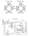
- Figs. l(a) and l(b) are diagrammatic representations illustrating a principle of a pole change motor (PAM motor), and in those figures, reference symbols la, lb, 2a, 2b, 3a, 3b, 4a, and 4b designate each a stator winding (each modelled for one phase), and reference symbol 5 designates a pole (indicated by N or S) of a rotating magnetic field.
- PAM motor pole change motor
- Fig. 2 is a circuit diagram illustrating a principle of a pole change system for a PAM motor, and in this figure, reference symbol 6 designates stator windings including windings 61a, 61b, 62a, 62b, 63a and 63b and having terminals U 1 , U 2 , V 1 , V 2 , W l and W 2' respectively.
- Reference symbols 7, 8 and 9 denote each a switch, VR, VS and VT denote power supply voltages of R, S and T phases of a three-phase power source, respectively, and reference symbol o designates a neutral point of the three-phase voltages. Referring to Fig.
- reference symbol 10 designates an electric motor, 11 a ventilator, 12 a shaft which interconnects the electric motor 10 and the ventilator 11, and 14 an air course resistance controlling mechanism including a bar 14a which is moved up and down to move a damper 14b accordingly to increase or decrease a resistance of an air course.
- Referring symbol 13 denotes a controlling signal which indicates an opening of the damper 14b necessary for the air flow resistance controlling mechanism 14, and reference symbols 15 and 16 designate an entrance and an exit of the air course, respectively.
- Fig. l(a) is a diagrammatic representation, in a modelled form, of a pole change motor having four poles therein while the motor is used as an electric motor having six poles therein by reversing the polarity of electric currents flowing through the coils 2b, 3a, 3b and 4a which are shown in broken lines in Fig. l(b).
- a PAM motor having variable poles therein can be obtained by changing connections of some of its stator windings to change coil currents.
- Fig. l(a) and l(b) illustrate an example wherein the polarity of electric currents is changed, the polarity may otherwise be changed by changing phase currents.
- the electric motor in Fig. 2 is run at a low speed with the switch 7 closed and with the switches 8 and 9 opened, and on the contrary, it is run at a high speed with the switch 7 closed and with the switches 8 and 9 closed to change the electric currents flowing through the stator windings 6 to change the number of poles of the motor.
- the coil 61b of Fig. 2 is connected between the terminal U 2 and the neutral point o and the direction of the electric current flowing therethrough does not change after changing of the number of poles. Accordingly, the coil 61b corresponds to the coil la, lb, 2a or 4b of Figs. l(a) and l(b).
- the coil 61a is connected between the terminals U 1 and U 2 and the direction of the electric current flowing therethrough changes after changing of the number of poles. Accordingly, the coil 61a corresponds to the coil 2b, 3a, 3b or 4a of Figs. l(a) and l(b). Since the rotational frequency n of an electric motor is given by a following expression,
- the rotational frequency of the PAM motor is changed by changing over of the switches 7, 8 and 9 of Fig. 2.
- Rotation of the PAM motor is transmitted to the ventilator 11 through a rotor 10 of the motor and the shaft 12.
- a signal representative of a deviation of an actual air flow at present from a required air flow is delivered as a controlling signal 13 to the air course resistance controlling mechanism 14.
- the bar 14a is moved up or down in response to the controlling signal 13 to move the damper 14b accordingly to control the air flow.
- a conventional air flow controlling apparatus is constructed as described above, when a PAM motor is to be changed over from a high speed to a low speed running or vice versa, harmonization between variation of an air flow due to variation of the rotational frequency and variation of an air flow by means of the damper 14b cannot be attained in a transient state in which the rotational frequency of the PAM motor varies. Accordingly, where a load to the fan is a boiler or the like, there may be a risk that a fire of the boiler during combustion goes out, a change of an internal pressure reaches a limit to explosion of the boiler, and so on. Thus, the conventional air flow controlling apparatus is disadvantageous in that a PAM motor cannot be applied thereto.
- an air flow controlling apparatus has also been put into practice wherein a motor which is driven from a movable frequency power source is employed as a motor for driving a fan in order to accomplish regulation of an air flow of the boiler as described above.
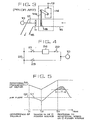
- the motor 10 receives supply of power alternatively from a movable frequency power source 24 (hereinafter referred to as "V power source”) or a commercial power source 25 (hereinafter referred to as "C power source”) depending upon open and closed conditions of the switches 21, 22 and 23.
- V power source movable frequency power source
- C power source commercial power source
- reference symbols t 1 , t 2 and t 3 designate a point of time at which the trouble has occurred to the V power source 24, another point of time at which the C power source 25 is coupled, and a further point of time at which rotation of the motor reaches a particular rotational frequency determined.in accordance with the frequency of the C power source, respectively.
- the conventional boiler air flow controlling apparatus is constructed as described above. Accordingly, the conventional boiler air flow controlling apparatus is disadvantageous in that, if a trouble occurs to the V power source and thus supply of power is changed over to the C power source, the rotational frequency of the motor (and hence the first fan 1) rises suddenly to increase an air flow while controlling of an air flow by means of the damper 14b is slow in responsiveness so that a wind pressure within the boiler increases to deteriorate safe running of the boiler, resulting in the necessity of tripping of the boiler.
- the damper 14b is slow in responsiveness so that a wind pressure within the boiler increases to deteriorate safe running of the boiler, resulting in the necessity of tripping of the boiler.
- the rotational frequency N 1 of the motor decreases and the air flow Q 1 by the first fan 1 decreases accordingly.
- the motor is energized by the C power source so that the rotational frequency N 1 of the motor rises and the air flow Q rises accordingly.
- a predetermined level for example, 200 mmHg
- the conventional boiler air flow controlling apparatus having the construction as shown in Fig. 4 has a defect that the boiler must be tripped (stopped) at a point of time when such a dangerous range is entered.
- a variation of an inner pressure of a boiler arising from a difference between two rotational speeds of a fan or fans which appears when the number of poles of the motor is changed is restricted to an allowable range by adjusting the opening of a damper located in an air course.
- the present invention further provides a boiler air flow controlling apparatus which can effectively control a variation of an inner pressure of a boiler which may appear when supply of power for either one of two fans is changed over from a variable frequency power source to a commercial power source.
- Fig. 6 is a diagrammatic representation showing a general construction of an air blowing system to which the present invention is applied, and reference symbols l0A and 10B designate first and third electric motors, respectively, 11A and 11B first and second fans, respectively, 12A and 12B first and second shafts, respectively, 15A and 15B air entrances of the first and second fans 11A and 11B, respectively, 16A and 16B air exits of the first and second fans 11A and 11B, respectively, reference symbol 17 designates a boiler, and 18 an ignition opening of the boiler 17. While not shown in Fig. 3, adjacent the air entrances 15A and 15B, there are located mechanisms 14A and 14B which each correspond to the air course resistance controlling mechanism 14 of Fig. 3.
- Fig. 7 is a diagram illustrating variations of an air flow when the PAM motor of Fig. 4 is changed over from low speed to high speed running.
- reference symbols Q I and Q 2 designate each an air flow of the fan 11A or 11B, L 1 , L 2 and L 3 levels of the air flows Q 1 , Q 2 and Q 1 -Q 2 before a changing over operation, t 1 , t 2 and t 3 points of time at which the motor is changed over from low to high speed running, t 1 being a time when application of a voltage is interrupted during running at a low speed, t 2 being a time when application of a voltage begins during running at a high speed, and t 3 being a time when a predetermined rotational frequency for the high speed is reached, and reference symbol T designates a period of time in which the air flow Q 1 is excessively high.
- the air flow Q l of Fig. 7 first decreases since supply of a voltage during running at a low speed is interrupted (at the point of time t l ) to deenergize the motor until the point of time t 2 at which a voltage for a high speed running is supplied to the motor. Consequently, the speed of the motor rises to increase the air flow until the high speed running is reached at the point of time t 3 . After the time t 3 , the air flow returns to and is stabilized at the initial level L 1 by operation of the air course resistance controlling mechanism 14A.
- controlling of an air flow according to the present invention can apparently be employed together with any other air flow controlling method.
- the present invention also provides a boiler air flow controlling apparatus which can cope with a trouble of a.V power source.
- a boiler air flow controlling apparatus which can cope with a trouble of a.V power source.
- Such an apparatus is illustrated in Fig. 8, in which elements corresponding to those shown in Fig. 3 are designated by like reference symbols.
- the air course resistance controlling mechanism 14 illustrated in Fig. 8 has an additional control input terminal 19 at which it receives, if a trouble has occurred to the V power source for the motor 10, a controlling signal for adjusting the opening of the damper 14b to restrict an excessive rise of a wind pressure within the boiler.
- Fig. 9 Conditions of controlling of a wind pressure by this apparatus are illustrated in Fig. 9. If a signal representative of a variation of an air flow corresponding to the air flow Q 2 is provided to the control input terminal 19 for the second fan 11B, a wind pressure within the boiler 17 is reduced to a value corresponding to the difference Q l -Q 2 of the air flows which is lower than a critical wind pressure of the boiler. Ideally, the difference Q 1 -Q 2 of the air flows should be equal to a reference value (-5 to -10 mmHg or so), but practically, it may be any value which is sufficiently below the critical wind pressure of the boiler.
- the instruction regarding the air flow 0 2 may be attained, for example, by an opening signal of a predetermined duration delivered to the damper of the second fan 11B and a. subsequent closing signal so as to return the air flow to the level before occurrence of the trouble of the V power source, or the like.
- the second fan 11B may otherwise be driven from a V power source. Or else, the first fan 11A and the second fan 11B may both be driven from a V power source or respective V power sources.
- the controlling signal to the damper 14b is replaced by a signal for varying an output frequency of the V power source.
- a controlling signal can be provided similarly to any other means such as a vane or the like.
- controlling input terminals 13 and 19 of the air course resistance controlling mechanism 14 of Fig. 5 are shown separately in order to give definite description, a signal delivered to the controlling input terminal 19 may be provided also to the other controlling input terminal 13.
- an air flow controlling apparatus according to the present invention may naturally be used together with any other air flow controlling system.
- the present invention when a PAM motor of one of air flow controlling systems is to be changed over from a high to a low speed running or vice versa, the other air flow controlling system is first rendered operative prior to the operation of the one air flow controlling system. Accordingly, the present invention presents an effect that running of a boiler can be continued with the inner pressure of a boiler furnace maintained in safety.
- the present invention presents another effect that, even upon occurrence of a trouble to the V power source, running of a boiler can be continued without stopping (tripping) of the boiler.
Landscapes
- Engineering & Computer Science (AREA)
- Chemical & Material Sciences (AREA)
- Combustion & Propulsion (AREA)
- Mechanical Engineering (AREA)
- General Engineering & Computer Science (AREA)
- Physics & Mathematics (AREA)
- Thermal Sciences (AREA)
- Regulation And Control Of Combustion (AREA)
- Control Of Positive-Displacement Air Blowers (AREA)
Applications Claiming Priority (4)
| Application Number | Priority Date | Filing Date | Title |
|---|---|---|---|
| JP118982/83 | 1983-06-28 | ||
| JP11898283A JPS608623A (ja) | 1983-06-28 | 1983-06-28 | ボイラ風量制御装置 |
| JP228835/83 | 1983-12-01 | ||
| JP22883583A JPS60120102A (ja) | 1983-12-01 | 1983-12-01 | ボイラ風量制御装置 |
Publications (3)
| Publication Number | Publication Date |
|---|---|
| EP0129907A2 true EP0129907A2 (de) | 1985-01-02 |
| EP0129907A3 EP0129907A3 (en) | 1985-09-18 |
| EP0129907B1 EP0129907B1 (de) | 1988-09-07 |
Family
ID=26456806
Family Applications (1)
| Application Number | Title | Priority Date | Filing Date |
|---|---|---|---|
| EP84107297A Expired EP0129907B1 (de) | 1983-06-28 | 1984-06-26 | Vorrichtung zum Steuern der Kesselluft |
Country Status (5)
| Country | Link |
|---|---|
| US (1) | US4770340A (de) |
| EP (1) | EP0129907B1 (de) |
| KR (1) | KR890001325B1 (de) |
| CA (1) | CA1216346A (de) |
| DE (1) | DE3473917D1 (de) |
Cited By (1)
| Publication number | Priority date | Publication date | Assignee | Title |
|---|---|---|---|---|
| AU575685B2 (en) * | 1984-09-13 | 1988-08-04 | Rinnai Corporation | Warm air heater |
Families Citing this family (5)
| Publication number | Priority date | Publication date | Assignee | Title |
|---|---|---|---|---|
| US6133699A (en) * | 1996-01-19 | 2000-10-17 | Gas Research Institute | Method and apparatus for operating a plurality of motors with a single controller |
| US7275533B2 (en) * | 2003-03-06 | 2007-10-02 | Exhausto, Inc. | Pressure controller for a mechanical draft system |
| US20070209653A1 (en) * | 2003-03-06 | 2007-09-13 | Exhausto, Inc. | Pressure Controller for a Mechanical Draft System |
| US8294409B2 (en) | 2010-08-18 | 2012-10-23 | Hamilton Sundstrand Corporation | Control of pole-change induction motors |
| EP2871421B1 (de) * | 2013-11-07 | 2017-04-12 | Grundfos Holding A/S | Hydraulischer Verteiler für ein hydraulisches Heizungs- und/oder Kühlsystem |
Family Cites Families (6)
| Publication number | Priority date | Publication date | Assignee | Title |
|---|---|---|---|---|
| US1915101A (en) * | 1931-06-19 | 1933-06-20 | John M Hopwood | Draft control system |
| US3214931A (en) * | 1964-05-25 | 1965-11-02 | Trane Co | Thermostatic control for refrigeration systems |
| GB2083903B (en) * | 1980-09-13 | 1984-08-30 | Hpe Supplies Ltd | Heating unit |
| US4373662A (en) * | 1980-10-17 | 1983-02-15 | Honeywell Inc. | Integrated control system using a microprocessor |
| DE3279508D1 (en) * | 1981-07-27 | 1989-04-13 | Foster Wheeler Energy Ltd | A method of operating a combustion apparatus having a fired heater |
| JPS5893987A (ja) * | 1981-11-27 | 1983-06-03 | Kureha Chem Ind Co Ltd | 送風機の風量制御方法 |
-
1984
- 1984-05-15 KR KR1019840002623A patent/KR890001325B1/ko not_active Expired
- 1984-06-26 CA CA000457410A patent/CA1216346A/en not_active Expired
- 1984-06-26 EP EP84107297A patent/EP0129907B1/de not_active Expired
- 1984-06-26 DE DE8484107297T patent/DE3473917D1/de not_active Expired
- 1984-06-27 US US06/625,248 patent/US4770340A/en not_active Expired - Fee Related
Cited By (1)
| Publication number | Priority date | Publication date | Assignee | Title |
|---|---|---|---|---|
| AU575685B2 (en) * | 1984-09-13 | 1988-08-04 | Rinnai Corporation | Warm air heater |
Also Published As
| Publication number | Publication date |
|---|---|
| KR850000643A (ko) | 1985-02-28 |
| CA1216346A (en) | 1987-01-06 |
| US4770340A (en) | 1988-09-13 |
| EP0129907B1 (de) | 1988-09-07 |
| EP0129907A3 (en) | 1985-09-18 |
| DE3473917D1 (en) | 1988-10-13 |
| KR890001325B1 (ko) | 1989-04-29 |
Similar Documents
| Publication | Publication Date | Title |
|---|---|---|
| KR890003934B1 (ko) | 풍량 제어방식 | |
| EP0139869B1 (de) | Regelsystem für einen polumschaltbaren elektrischen Motor | |
| US4684866A (en) | Adaptive controller for a motor vehicle engine throttle operator | |
| US4408150A (en) | Speed control system and method for electric motor | |
| EP0534447B1 (de) | Steuerungsschaltung eines Gleichstromgebläses zur linear verstellbarer Kühlung | |
| US4937513A (en) | Tapped auxiliary winding for multi-speed operation of electric motor and method therefor | |
| US5051639A (en) | Y-delta conversion switches on dual stator induction motor | |
| US4737701A (en) | Tapped auxiliary winding for multi-speed operation of electric motor and method therefor | |
| JPS623677B2 (de) | ||
| US4770340A (en) | Boiler air flow controlling apparatus | |
| US4870339A (en) | Variable-speed power generating system | |
| KR890002532B1 (ko) | 풍량 제어장치 | |
| SE8601802L (sv) | Forfarande och anordning for reglering av en motor | |
| SE8705106L (sv) | Foerfarande och anordning foer reglering av storlek och riktning hos en stroem genom en lindning | |
| US4977363A (en) | Overheat preventing system of A.C. motor | |
| KR900003799B1 (ko) | 제어 시스템 | |
| JPS58225617A (ja) | 変圧器冷却装置 | |
| JP2792224B2 (ja) | 空気調和機の制御装置 | |
| SU769694A2 (ru) | Устройство дл двухзонного регулировани скорости | |
| JPS5913311A (ja) | 変圧器冷却装置 | |
| EP0324531A2 (de) | Durch Bremsung ausgelöste Freigabe einer mit einem elektrischen Motor angetriebenen Fahrtreglervorrichtung | |
| KR890003935B1 (ko) | 가변주파수 전원운전방식 | |
| KR900000767B1 (ko) | 전동기의 급전제어방식 | |
| SU886178A1 (ru) | Двухзонный вентильный электропривод | |
| JPH0341011B2 (de) |
Legal Events
| Date | Code | Title | Description |
|---|---|---|---|
| PUAI | Public reference made under article 153(3) epc to a published international application that has entered the european phase |
Free format text: ORIGINAL CODE: 0009012 |
|
| AK | Designated contracting states |
Designated state(s): CH DE GB LI |
|
| PUAL | Search report despatched |
Free format text: ORIGINAL CODE: 0009013 |
|
| AK | Designated contracting states |
Designated state(s): CH DE GB LI |
|
| 17P | Request for examination filed |
Effective date: 19851002 |
|
| 17Q | First examination report despatched |
Effective date: 19860421 |
|
| GRAA | (expected) grant |
Free format text: ORIGINAL CODE: 0009210 |
|
| AK | Designated contracting states |
Kind code of ref document: B1 Designated state(s): CH DE GB LI |
|
| REF | Corresponds to: |
Ref document number: 3473917 Country of ref document: DE Date of ref document: 19881013 |
|
| PLBE | No opposition filed within time limit |
Free format text: ORIGINAL CODE: 0009261 |
|
| STAA | Information on the status of an ep patent application or granted ep patent |
Free format text: STATUS: NO OPPOSITION FILED WITHIN TIME LIMIT |
|
| 26N | No opposition filed | ||
| PGFP | Annual fee paid to national office [announced via postgrant information from national office to epo] |
Ref country code: GB Payment date: 19930616 Year of fee payment: 10 |
|
| PGFP | Annual fee paid to national office [announced via postgrant information from national office to epo] |
Ref country code: CH Payment date: 19930628 Year of fee payment: 10 |
|
| PGFP | Annual fee paid to national office [announced via postgrant information from national office to epo] |
Ref country code: DE Payment date: 19930630 Year of fee payment: 10 |
|
| PG25 | Lapsed in a contracting state [announced via postgrant information from national office to epo] |
Ref country code: GB Effective date: 19940626 |
|
| PG25 | Lapsed in a contracting state [announced via postgrant information from national office to epo] |
Ref country code: LI Effective date: 19940630 Ref country code: CH Effective date: 19940630 |
|
| GBPC | Gb: european patent ceased through non-payment of renewal fee |
Effective date: 19940626 |
|
| REG | Reference to a national code |
Ref country code: CH Ref legal event code: PL |
|
| PG25 | Lapsed in a contracting state [announced via postgrant information from national office to epo] |
Ref country code: DE Effective date: 19950301 |