US6133699A - Method and apparatus for operating a plurality of motors with a single controller - Google Patents
Method and apparatus for operating a plurality of motors with a single controller Download PDFInfo
- Publication number
- US6133699A US6133699A US08/733,532 US73353296A US6133699A US 6133699 A US6133699 A US 6133699A US 73353296 A US73353296 A US 73353296A US 6133699 A US6133699 A US 6133699A
- Authority
- US
- United States
- Prior art keywords
- motor
- motors
- controller
- furnace
- standard furnace
- Prior art date
- Legal status (The legal status is an assumption and is not a legal conclusion. Google has not performed a legal analysis and makes no representation as to the accuracy of the status listed.)
- Expired - Lifetime
Links
- 238000000034 method Methods 0.000 title claims abstract description 11
- 239000007789 gas Substances 0.000 claims description 7
- 230000000630 rising effect Effects 0.000 claims 1
- 239000003990 capacitor Substances 0.000 description 10
- 230000001143 conditioned effect Effects 0.000 description 4
- 238000010586 diagram Methods 0.000 description 4
- 230000006698 induction Effects 0.000 description 4
- 238000004804 winding Methods 0.000 description 4
- 230000001360 synchronised effect Effects 0.000 description 3
- 238000012986 modification Methods 0.000 description 2
- 230000004048 modification Effects 0.000 description 2
- 230000003750 conditioning effect Effects 0.000 description 1
- 230000003247 decreasing effect Effects 0.000 description 1
- 238000004519 manufacturing process Methods 0.000 description 1
- 230000002441 reversible effect Effects 0.000 description 1
Images

Classifications
-
- H—ELECTRICITY
- H02—GENERATION; CONVERSION OR DISTRIBUTION OF ELECTRIC POWER
- H02P—CONTROL OR REGULATION OF ELECTRIC MOTORS, ELECTRIC GENERATORS OR DYNAMO-ELECTRIC CONVERTERS; CONTROLLING TRANSFORMERS, REACTORS OR CHOKE COILS
- H02P1/00—Arrangements for starting electric motors or dynamo-electric converters
- H02P1/16—Arrangements for starting electric motors or dynamo-electric converters for starting dynamo-electric motors or dynamo-electric converters
- H02P1/42—Arrangements for starting electric motors or dynamo-electric converters for starting dynamo-electric motors or dynamo-electric converters for starting an individual single-phase induction motor
-
- H—ELECTRICITY
- H02—GENERATION; CONVERSION OR DISTRIBUTION OF ELECTRIC POWER
- H02P—CONTROL OR REGULATION OF ELECTRIC MOTORS, ELECTRIC GENERATORS OR DYNAMO-ELECTRIC CONVERTERS; CONTROLLING TRANSFORMERS, REACTORS OR CHOKE COILS
- H02P25/00—Arrangements or methods for the control of AC motors characterised by the kind of AC motor or by structural details
- H02P25/02—Arrangements or methods for the control of AC motors characterised by the kind of AC motor or by structural details characterised by the kind of motor
- H02P25/04—Single phase motors, e.g. capacitor motors
-
- H—ELECTRICITY
- H02—GENERATION; CONVERSION OR DISTRIBUTION OF ELECTRIC POWER
- H02P—CONTROL OR REGULATION OF ELECTRIC MOTORS, ELECTRIC GENERATORS OR DYNAMO-ELECTRIC CONVERTERS; CONTROLLING TRANSFORMERS, REACTORS OR CHOKE COILS
- H02P2207/00—Indexing scheme relating to controlling arrangements characterised by the type of motor
- H02P2207/05—Synchronous machines, e.g. with permanent magnets or DC excitation
Definitions
- the present invention relates in general to electric motors and, in particular, to a system in which a single controller is used to control two or more motors.
- This invention has particular application in HVAC systems.
- furnaces include a main blower that forces the heated (or cooled) air into the supply duct for distribution throughout a zone (or zones) to be conditioned.
- furnaces have been additionally equipped with a second, smaller blower, called an induced draft blower, which draws exhaust gasses out of the furnace.
- This induced draft blower is matched to the main blower such that these two blowers work in combination to provide efficient conditioning of a particular space.
- furnaces were controlled such that they would continue to distribute conditioned air (i.e. heated or cooled) to the desired zone or zones at 100% power, intentionally overshooting the desired temperature, and then shutting down completely until the conditioned zone fell significantly below the desired temperature after which the zone was heated again at 100% power. It has been found, however, that a desired temperature can be more efficiently reached and then maintained by running the furnace at 100% when the temperature of a zone is significantly below the desired temperature and then at 25-60% of its maximum power over a longer period of time to maintain the zone at or about desired temperature. This approach can result in a significant cost-savings to the user, while also providing increased comfort.
- conditioned air i.e. heated or cooled
- This lower power mode allows for and requires a reduced gas input and slower rotation of both the main (circulating) and induced draft blowers to maintain proper furnace operation.
- This desired adjustability can be easily achieved with today's modern speed controllers, which are available for most motors. Necessarily, however, each controller adds to the cost of its associated motor and, in turn, the overall system into which the motors are installed. Accordingly, it is an object of the present invention to provide a control scheme in which a plurality of associated motors can be controlled by a single controller.
- the present invention comprises a system for operating a plurality of motors with a single controller.
- the system includes a first motor, a second motor, and controller.
- the second motor is matched to the first motor and may or may not have a lower power rating than the first motor.
- the controller electrically drives the first and second motors with a modulated voltage (such as a sine wave or pulse modulated signal) at one set frequency.
- the controller is capable of generating different frequency signals based upon the desired speed for the first and second motors.
- first and second motors can be of any type of motor and are usually selected to perform work in combination with one another in a set ratio.
- One particular application is running the fans for a furnace.
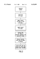
- This system can be installed into a standard furnace with two motors controlled by a single controller by: installing a first motor in the standard furnace, the first motor having a controller; matching a second motor to the first motor; installing the second motor in the standard furnace; connecting the second motor to the controller associated with the first motor; and controlling the first and second motors with the controller associated with the first motor. Where necessary the current from the controller can be limited or boosted such that the desired operating parameters are achieved.
- FIG. 1 of the drawings is a schematic block diagram of the system for operating a plurality of motors with a single controller
- FIG. 2 of the drawings is a schematic block diagram of one possible controller for use in the present system.
- FIG. 3 of the drawings is a flow diagram of the method for constructing a system for operating a plurality of motors with a single controller.
- FIG. 1 of the drawings is a schematic block diagram of system 100 for operating a plurality of motors with a single controller.
- System 100 includes controller 101, first motor 102 and second motor 103.
- the system further includes relay pairs 105 and 106, which disconnect their associated motor from controller 101, in the event that, that motor's operation is not required. This functionality is achieved by interposing relay 105 between controller 101 and first motor 102 and relay 106 between controller 101 and second motor 102.
- Controller 101 is electrically connected to both first motor 102 and second motor 103.
- a three-phase power system is shown in FIG. 1, the present invention works equally well in one- and two-phase power systems, as would be readily understood by one of ordinary skill in the art with the present disclosure before them.
- Controller 101 generates and provides a constant frequency voltage to drive first motor 102 and second motor 103 at various constant frequencies. While this constant frequency voltage will generally be a sine wave, a pulse width modulated signal and other variable DC signals will also work well. The frequency of this drive voltage is based upon the desired output of the first and second AC motors. As shown in FIG. 2, controller 101 includes speed controller 110 and driver stage 120. In a preferred embodiment, speed controller 110 may generate two- or three-phase power signals which control driver stage 120 to provide a voltage and current at the desired operating range with desired signal characteristics. Controller 101 may additionally include voltage regulator 130 and current sense feedback loop 140. Controller 101 generates a particular modulated (sine-like) signal based on input provided by external control signal 170 such as from a thermostat.
- external control signal 170 such as from a thermostat.
- Control signal 170 may be an analog voltage, digital signal, pulse width modulated signal or other signal for conveying the control value based on information from any number of apparatuses such as thermostats and operator control panels. Additional control circuitry may be necessary to convert control signal 170 into a readable signal for speed controller 110. Such circuitry and the details associated therewith, would be apparent to one with ordinary skill in the art.
- First motor 102 and second motor 103 of FIG. 1 are AC motors of the three-, two- or single- phase type, although two- or three-phase type AC motors are preferred.
- these motors can be of either the synchronous or induction type. In either event, at their drive frequencies both of these types of AC motors act synchronously. While both motor types work equally well, induction AC motors are more common than synchronous motors.
- Various types of AC induction motors including the split phase motor, permanent split capacitor motor, capacitor start/capacitor run motor are well known in the art.
- the associated controller would have to generate the variable frequency voltages to primary winding required for a variable speed motor, as well as the 90° phase shifted version of the selected variable frequency voltage to secondary winding of these capacitor motors, as disclosed in the co-pending application.
- first motor 102 and second motor 103 are selected such that they match (i.e. the two motors will run at the same speed, less the slip in rpm required for each to produce the desired torque).
- the desired result is motor speeds in these motors that track each other. Accordingly, while first motor 102 and second motor 103 could potentially be of different types (single-phase, two-phase, three-phase, synchronous, induction and all the possible derivative discussed hereinabove), selecting identical motor types will simplify the design and ensure appropriate performance of the overall system throughout the entire operating range.
- the first and second motors are both running fans. Consequently, the loads placed thereon are not relatively great, especially at lower rpms.
- the power to run a fan is proportional to the cube of the rpm. Thus, reducing the speed in half would require only one eighth the power.
- a three phase motor at 1 hp has ⁇ 4% slip at its rated load, which means it will run at least 1728 rpm. In the case of reduced loads (lower speed), the slip will be even less, thus, allowing the motors to track very closely when driven off a common controller.
Landscapes
- Engineering & Computer Science (AREA)
- Power Engineering (AREA)
- Control Of Multiple Motors (AREA)
Abstract
Description
Claims (13)
Priority Applications (3)
| Application Number | Priority Date | Filing Date | Title |
|---|---|---|---|
| US08/733,532 US6133699A (en) | 1996-01-19 | 1996-10-18 | Method and apparatus for operating a plurality of motors with a single controller |
| US08/784,144 US5932981A (en) | 1996-01-19 | 1997-01-17 | Apparatus and method for reduced voltage controller |
| US08/784,143 US5796234A (en) | 1996-01-19 | 1997-01-17 | Variable speed motor apparatus and method for forming same from a split capacitor motor |
Applications Claiming Priority (2)
| Application Number | Priority Date | Filing Date | Title |
|---|---|---|---|
| US1027496P | 1996-01-19 | 1996-01-19 | |
| US08/733,532 US6133699A (en) | 1996-01-19 | 1996-10-18 | Method and apparatus for operating a plurality of motors with a single controller |
Related Child Applications (2)
| Application Number | Title | Priority Date | Filing Date |
|---|---|---|---|
| US08/784,143 Continuation-In-Part US5796234A (en) | 1996-01-19 | 1997-01-17 | Variable speed motor apparatus and method for forming same from a split capacitor motor |
| US08/784,144 Continuation-In-Part US5932981A (en) | 1996-01-19 | 1997-01-17 | Apparatus and method for reduced voltage controller |
Publications (1)
| Publication Number | Publication Date |
|---|---|
| US6133699A true US6133699A (en) | 2000-10-17 |
Family
ID=26680987
Family Applications (1)
| Application Number | Title | Priority Date | Filing Date |
|---|---|---|---|
| US08/733,532 Expired - Lifetime US6133699A (en) | 1996-01-19 | 1996-10-18 | Method and apparatus for operating a plurality of motors with a single controller |
Country Status (1)
| Country | Link |
|---|---|
| US (1) | US6133699A (en) |
Cited By (10)
| Publication number | Priority date | Publication date | Assignee | Title |
|---|---|---|---|---|
| US6434885B1 (en) * | 1997-12-01 | 2002-08-20 | Meteor Gummiwerke K.H. Bädje Gmbh & Co. | Moveable window unit having a noise reduction system |
| US20040253559A1 (en) * | 2003-06-12 | 2004-12-16 | Honeywell International Inc. | Premix burner for warm air furnace |
| US20040250810A1 (en) * | 2003-06-12 | 2004-12-16 | Honeywell International Inc. | Warm air furnace with premix burner |
| US20050029816A1 (en) * | 2000-10-26 | 2005-02-10 | Dennis Brandon | Electric generator and motor drive system |
| US20050151019A1 (en) * | 2003-12-18 | 2005-07-14 | Curtis Edgar Stevens | Electrically pressurized on-board inert gas generation system |
| US8545214B2 (en) | 2008-05-27 | 2013-10-01 | Honeywell International Inc. | Combustion blower control for modulating furnace |
| US8764435B2 (en) | 2008-07-10 | 2014-07-01 | Honeywell International Inc. | Burner firing rate determination for modulating furnace |
| US8876524B2 (en) | 2012-03-02 | 2014-11-04 | Honeywell International Inc. | Furnace with modulating firing rate adaptation |
| US11196362B2 (en) | 2017-10-30 | 2021-12-07 | Annexair Inc. | System for controlling a plurality of synchronous permanent magnet electronically commutated motors |
| US12480527B2 (en) | 2022-10-07 | 2025-11-25 | Hamilton Sundstrand Corporation | High-power air-coooled compressor motor and low-power cooling booster fan motor powered by single inverter |
Citations (11)
| Publication number | Priority date | Publication date | Assignee | Title |
|---|---|---|---|---|
| US3621350A (en) * | 1968-06-19 | 1971-11-16 | Dowty Rotol Ltd | Time integral control system |
| US4142828A (en) * | 1976-06-04 | 1979-03-06 | Mitsubishi Jukogyo Kabushiki Kaisha | Openable rotor chamber construction for a vertical blower |
| US4196376A (en) * | 1977-05-13 | 1980-04-01 | Danfoss A/S | Rotary speed ratio control arrangement |
| US4663536A (en) * | 1985-03-04 | 1987-05-05 | Precise Power Corporation | A.C. motor-generator |
| US4770340A (en) * | 1983-06-28 | 1988-09-13 | Mitsubishi Denki Kabushiki Kaisha | Boiler air flow controlling apparatus |
| US4825131A (en) * | 1986-11-05 | 1989-04-25 | Hitachi, Ltd. | Control system for induction motor driven electric car |
| US4879475A (en) * | 1986-10-03 | 1989-11-07 | W. Schlafhorst & Co. | Device and method for maintaining a voltage level in a control circuit |
| US4939438A (en) * | 1986-03-14 | 1990-07-03 | Orbital Sciences Corporation Ii | Relay control assembly |
| US5019755A (en) * | 1989-04-11 | 1991-05-28 | Walker David E | Electric motor drive system |
| US5029265A (en) * | 1990-01-11 | 1991-07-02 | Staats Gustav W | Motor controller having a control loop for neutralizing rotor leakage and magnetizing reactances |
| US5266787A (en) * | 1991-01-11 | 1993-11-30 | Symbol Technologies, Inc. | Laser scanner using two scan motors independently controlled by a single signal |
-
1996
- 1996-10-18 US US08/733,532 patent/US6133699A/en not_active Expired - Lifetime
Patent Citations (11)
| Publication number | Priority date | Publication date | Assignee | Title |
|---|---|---|---|---|
| US3621350A (en) * | 1968-06-19 | 1971-11-16 | Dowty Rotol Ltd | Time integral control system |
| US4142828A (en) * | 1976-06-04 | 1979-03-06 | Mitsubishi Jukogyo Kabushiki Kaisha | Openable rotor chamber construction for a vertical blower |
| US4196376A (en) * | 1977-05-13 | 1980-04-01 | Danfoss A/S | Rotary speed ratio control arrangement |
| US4770340A (en) * | 1983-06-28 | 1988-09-13 | Mitsubishi Denki Kabushiki Kaisha | Boiler air flow controlling apparatus |
| US4663536A (en) * | 1985-03-04 | 1987-05-05 | Precise Power Corporation | A.C. motor-generator |
| US4939438A (en) * | 1986-03-14 | 1990-07-03 | Orbital Sciences Corporation Ii | Relay control assembly |
| US4879475A (en) * | 1986-10-03 | 1989-11-07 | W. Schlafhorst & Co. | Device and method for maintaining a voltage level in a control circuit |
| US4825131A (en) * | 1986-11-05 | 1989-04-25 | Hitachi, Ltd. | Control system for induction motor driven electric car |
| US5019755A (en) * | 1989-04-11 | 1991-05-28 | Walker David E | Electric motor drive system |
| US5029265A (en) * | 1990-01-11 | 1991-07-02 | Staats Gustav W | Motor controller having a control loop for neutralizing rotor leakage and magnetizing reactances |
| US5266787A (en) * | 1991-01-11 | 1993-11-30 | Symbol Technologies, Inc. | Laser scanner using two scan motors independently controlled by a single signal |
Cited By (14)
| Publication number | Priority date | Publication date | Assignee | Title |
|---|---|---|---|---|
| US6434885B1 (en) * | 1997-12-01 | 2002-08-20 | Meteor Gummiwerke K.H. Bädje Gmbh & Co. | Moveable window unit having a noise reduction system |
| US20050029816A1 (en) * | 2000-10-26 | 2005-02-10 | Dennis Brandon | Electric generator and motor drive system |
| US6923643B2 (en) | 2003-06-12 | 2005-08-02 | Honeywell International Inc. | Premix burner for warm air furnace |
| US20040250810A1 (en) * | 2003-06-12 | 2004-12-16 | Honeywell International Inc. | Warm air furnace with premix burner |
| US6880548B2 (en) | 2003-06-12 | 2005-04-19 | Honeywell International Inc. | Warm air furnace with premix burner |
| US20040253559A1 (en) * | 2003-06-12 | 2004-12-16 | Honeywell International Inc. | Premix burner for warm air furnace |
| US20050151019A1 (en) * | 2003-12-18 | 2005-07-14 | Curtis Edgar Stevens | Electrically pressurized on-board inert gas generation system |
| US8545214B2 (en) | 2008-05-27 | 2013-10-01 | Honeywell International Inc. | Combustion blower control for modulating furnace |
| US10094593B2 (en) | 2008-05-27 | 2018-10-09 | Honeywell International Inc. | Combustion blower control for modulating furnace |
| US8764435B2 (en) | 2008-07-10 | 2014-07-01 | Honeywell International Inc. | Burner firing rate determination for modulating furnace |
| US8876524B2 (en) | 2012-03-02 | 2014-11-04 | Honeywell International Inc. | Furnace with modulating firing rate adaptation |
| US11196362B2 (en) | 2017-10-30 | 2021-12-07 | Annexair Inc. | System for controlling a plurality of synchronous permanent magnet electronically commutated motors |
| US11936323B2 (en) | 2017-10-30 | 2024-03-19 | Annexair Inc. | System for controlling a plurality of synchronous permanent magnet electronically commutated motors |
| US12480527B2 (en) | 2022-10-07 | 2025-11-25 | Hamilton Sundstrand Corporation | High-power air-coooled compressor motor and low-power cooling booster fan motor powered by single inverter |
Similar Documents
| Publication | Publication Date | Title |
|---|---|---|
| US5796234A (en) | Variable speed motor apparatus and method for forming same from a split capacitor motor | |
| US6952088B2 (en) | PSC motor system for use in HVAC applications with improved start-up | |
| US6801013B2 (en) | PSC motor system for use in HVAC applications | |
| US7272302B2 (en) | PSC motor system for use in HVAC applications with field adjustment and fail-safe capabilities | |
| US5818194A (en) | Direct replacement variable speed blower motor | |
| US6246207B1 (en) | Method and apparatus for controlling an induction motor | |
| US6864659B2 (en) | Variable speed controller for air moving applications using an AC induction motor | |
| US6133699A (en) | Method and apparatus for operating a plurality of motors with a single controller | |
| US9806660B1 (en) | Control system for hybrid operation of an electric motor | |
| US20100045105A1 (en) | Integrated multiple power conversion system for transport refrigeration units | |
| US7268505B2 (en) | Electric machine and method of operating the electric machine | |
| US9979328B1 (en) | Dual-drive electric motor control system and methods for hybrid operation of electric motors | |
| US9071183B2 (en) | Methods and systems for providing combined blower motor and draft inducer motor control | |
| JP4615008B2 (en) | System and method for increasing the output horsepower and efficiency of an electric motor | |
| US20070069683A1 (en) | Electric machine and method of operating the electric machine | |
| US9935576B1 (en) | Methods and controllers for operation of electric motors | |
| JP2520998B2 (en) | OPERATING FREQUENCY CONTROL DEVICE OF COMPRESSOR IN AIR CONDITIONER AND OPERATING FREQUENCY CONTROL METHOD THEREOF | |
| US12378969B2 (en) | Controller and drive circuit for electric motors | |
| US11689137B2 (en) | Controller and drive circuits for electric motors | |
| US7102324B2 (en) | Fixed speed drive | |
| JPS6120236B2 (en) | ||
| JPH09113039A (en) | Compressor heating device | |
| JP2020137273A (en) | Fan motor, electronic apparatus, and motor control method | |
| US11309822B2 (en) | Electric motors and drive circuits therefor | |
| US20230402948A1 (en) | Automatic control system for phase angle of motor |
Legal Events
| Date | Code | Title | Description |
|---|---|---|---|
| AS | Assignment |
Owner name: GAS RESEARCH INSTITUTE, ILLINOIS Free format text: ASSIGNMENT OF ASSIGNORS INTEREST;ASSIGNORS:VRIONIS, NICK G.;RUSS, ROBERT M.;BLAU, DAVE;AND OTHERS;REEL/FRAME:008294/0562 Effective date: 19961001 |
|
| STCF | Information on status: patent grant |
Free format text: PATENTED CASE |
|
| AS | Assignment |
Owner name: VARIDIGM CORPORATION, MINNESOTA Free format text: ASSIGNMENT OF ASSIGNORS INTEREST;ASSIGNOR:GAS RESEARCH INSTITUTE;REEL/FRAME:013231/0921 Effective date: 20020301 |
|
| REMI | Maintenance fee reminder mailed | ||
| FPAY | Fee payment |
Year of fee payment: 4 |
|
| SULP | Surcharge for late payment | ||
| FPAY | Fee payment |
Year of fee payment: 8 |
|
| FPAY | Fee payment |
Year of fee payment: 12 |
|
| AS | Assignment |
Owner name: ACACIA RESEARCH GROUP LLC, TEXAS Free format text: ASSIGNMENT OF ASSIGNORS INTEREST;ASSIGNOR:VARIDIGM CORPORATION;REEL/FRAME:029013/0427 Effective date: 20120831 Owner name: HVAC MODULATION TECHNOLOGIES LLC, TEXAS Free format text: ASSIGNMENT OF ASSIGNORS INTEREST;ASSIGNOR:ACACIA RESEARCH GROUP LLC;REEL/FRAME:029013/0580 Effective date: 20120918 |