EP0129475A2 - Magnetischer Drehzahlmesser für Plattenlaufwerk - Google Patents
Magnetischer Drehzahlmesser für Plattenlaufwerk Download PDFInfo
- Publication number
- EP0129475A2 EP0129475A2 EP84401223A EP84401223A EP0129475A2 EP 0129475 A2 EP0129475 A2 EP 0129475A2 EP 84401223 A EP84401223 A EP 84401223A EP 84401223 A EP84401223 A EP 84401223A EP 0129475 A2 EP0129475 A2 EP 0129475A2
- Authority
- EP
- European Patent Office
- Prior art keywords
- magnet
- coil
- tachometer
- armature
- magnetic
- Prior art date
- Legal status (The legal status is an assumption and is not a legal conclusion. Google has not performed a legal analysis and makes no representation as to the accuracy of the status listed.)
- Granted
Links
Images
Classifications
-
- G—PHYSICS
- G01—MEASURING; TESTING
- G01P—MEASURING LINEAR OR ANGULAR SPEED, ACCELERATION, DECELERATION, OR SHOCK; INDICATING PRESENCE, ABSENCE, OR DIRECTION, OF MOVEMENT
- G01P3/00—Measuring linear or angular speed; Measuring differences of linear or angular speeds
- G01P3/42—Devices characterised by the use of electric or magnetic means
- G01P3/44—Devices characterised by the use of electric or magnetic means for measuring angular speed
- G01P3/46—Devices characterised by the use of electric or magnetic means for measuring angular speed by measuring amplitude of generated current or voltage
- G01P3/465—Devices characterised by the use of electric or magnetic means for measuring angular speed by measuring amplitude of generated current or voltage by using dynamo-electro tachometers or electric generator
-
- G—PHYSICS
- G11—INFORMATION STORAGE
- G11B—INFORMATION STORAGE BASED ON RELATIVE MOVEMENT BETWEEN RECORD CARRIER AND TRANSDUCER
- G11B5/00—Recording by magnetisation or demagnetisation of a record carrier; Reproducing by magnetic means; Record carriers therefor
- G11B5/48—Disposition or mounting of heads or head supports relative to record carriers ; arrangements of heads, e.g. for scanning the record carrier to increase the relative speed
- G11B5/54—Disposition or mounting of heads or head supports relative to record carriers ; arrangements of heads, e.g. for scanning the record carrier to increase the relative speed with provision for moving the head into or out of its operative position or across tracks
- G11B5/55—Track change, selection or acquisition by displacement of the head
- G11B5/5521—Track change, selection or acquisition by displacement of the head across disk tracks
Definitions
- This invention relates to tachometers for monitoring the velocity of the read/write heads in a disk drive, and more specifically to tachometers for monitoring the velocity of a rotary actuator arm of a disk drive.
- a closed loop disk drive uses a servo system to accurately position the read/write head at a requested track.
- the servo system uses a dedicated disk surface on which servo information is written.
- no tachometer is needed, since the dedicated servo surface provides continuous feedback information.
- Obviously such systems have the disadvantage of having one less disk surface available for data storage, and for systems having one or two disks this represents a substantial storage loss.
- some applications use a tachometer, coupled to the head actuator, to relay velocity information to the serve system.
- the servo . system uses the head velocity signal as the continuous servo signal, this information being supplemented with fine positioning information stored on a small portion of each sector of each track and normally referred to as embedded serve information.
- a disk drive may use either linear or rotary actuator positioning means.
- the actuator arm, and therefore the head is moved linearly along a radius of the rotating disk, while in the rotary case, the actuator arm rotates along an axis parallel to the disk spindle at a point close to the outside rim of the disk.
- a suitable tachometer must be used.
- the available rotary tachometers are not designed for disk drive applications. They range from simple generators that measure the speed of the rotating shaft to more sophisticated optical decoders. Unfortunately they are either not sensitive enough, due in part to the lack of noise rejection and adequate bandwidth, or are too expensive for disk drive applications. Cost is an important factor in the manufacture of reasonably priced disk drives, thus an inexpensive tachometer is needed, provided that the required bandwith and noise rejection can be achieved.
- the present invention provides for an inexpensive magnetic tachometer which produces a bandwidth and noise rejection particularly suitable for disk drive applications.
- An elongated actuator arm hav.ing first and second end portions opposite each other, carries an electromagnetic transducer on the first end portion, the transducer being adapted to be used over a rotating magnetic disk.
- a magnet is disposed on the second end portion.
- a substantially longitudinal conductive coil is disposed adjacent the magnet at a position such that the path defined by the magnet throughout the range of motion of the actuator arm remains within an area defined by the projection of the coil's outer dimensions in the plane of the path of the magnet.
- two longitudinal coils are disposed parallel to each other to define an elongated region in which a magnet, positioned on the counter-balance end of a rotary actuator arm, is free to move as the arm rotates through selected positions.
- the ceil assembly is rigidly supported on a frame mounted on the casing of the servo motor.
- the structure of the coil assembly helps to reduce costs, since the two coils can be simultaneously wound ever a single elongated armature/filler subassembly.
- This subassembly is then snapped in two and bent over spacers to form a rigid coil assembly.
- a flexible conductor is used to provide a connection to the coils.
- the armature is a thin, elongated, low-loss member and is magnetically saturated by the magnetic field available from the magnet.
- the two coils are differentially coupled to provide common mode rejection. The saturation of the magnetic circuit, the differentially coupled coils and the direct coupling of the magnet to the actuator arm contribute to provide a magnetic tachometor having sufficiently large bandwidth and noise rejection for disk drive applications.
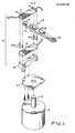
- Tachometer assembly 10 comprises two coils 12 and 14 disposed parallel to each other to define an elongated region therebetween. Within this region there is located a disk-shaped magnet 16 which has the opposite polarity poles on the two opposite surfaces and is imbedded in the counter weight portion 22 of arm 20. Attached to the opposite end of arm 20 is read/write head 26 which is used to read or write magnetically encoded information on one surface of a magnetic disk (not shown). The read/write head 26 has a set of wires 28 running from its magnetic core and coil assembly along the elongated portion 24 of arm 20 for conventional connection to suitable read/write circuitry. Arm 20 is attached to the shaft 32 of rotary servo motor 30. Servo motor 30 rotates the arm 20 through a predetermined arc and therefore positions head 26 at a location corresponding to the desired track on the disk.
- Tachometer assembly 10 is fastened to and supported by block 40 which is secured to plate 42.
- Plate 12 is secured to the casing of servo motor 30 and is used, together with block 40, to support tachometer assembly 10 at an appropriate fixed position with respect to the movable arm. The appropriate position is such that the projected region between the two coils encloses arm magnet 16 throughout the permitted movement range of arm 20.
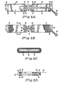
- Each of the two coils 12 and 14 is wound on a corresponding coil support formed by armature plate 52 and filler 54.
- Armature plate 52 is a thin U-shaped elongated plate of electrical steel. The bent edges forming the U provide the required amount of stiffness to the structure.
- the area within the U is filled with a slab of plastic filler 54 to support the coils.
- the two coils 12 and 14 are formed by winding insulated copper wire over a central portion of armature plate 52/filler 54 assembly.
- plastic filler 54 includes two end shoulders 58 which extend up to the top surface of the coil to provide an overall flush surface.
- the electrical connection to the coils is made by using a flexible conductor cable 60.
- a first conductor is connected to pad 62 where the beginning of the winding of coil 12 is soldered.
- a second conductor is connected first to pad 64 where the end of the winding of coil 12 is soldered.
- This second conductor then continues and is connected to pad 66 where the beginning of the winding of coil 14 is also soldered.
- the third conductor is coupled to pad 68 where the end of the winding of coil 14 is also soldered.
- the coils 12 and 14 are wound in the same direction with respect to the beginning of their respective windings,and each end of the winding is brought back to a pad, 68 and 64 respectively, adjacent the location of the beginning of windings.
- the portion of flex cable 60 connected to coil 14 is placed on a suitable longitudinal groove formed in filler 54, and it is held in place by coil 12.
- a preferred method of manufacture for tachometer assembly 10 uses a one piece plastic insert 70 having two ends 54, as described above, connected by a central breakaway portion 72. To each of the two ends 54 there is bonded, by conventional means, armature piece 52. Flex connector 60 is then connected to solder pads 62, 64, 66, and 68. To insulate the windings from the armature, a thin sheet of mylar tape is applied over the armature. The coils 12 and 16 are then wound simultaneously and in the same direction starting from solder pads 62 and 66, respectively. At the end of the winding step the coil wire is brought back and soldered to pads 64 and 6 ⁇ respectively. A further layer of insulation is placed over the coils, for example by using mylar shrink tubing.
- the wound assembly is now bent causing the center portion 72 of plastic insert 70 to breakaway at four break points 74.
- the two wound coil subassemblies, now only connected by flex cable 50, are folded, and four cylindrical spacers 76 are used to complete the tachometer assembly.
- Each spacer 76 has reduced diameter hollow end portions which fit into corresponding holes in armature plate 52 and held the two coils 12 and 14 at a predetermined separation.
- a conical swaging tool is used to lock the spacers to the two armatures.
- Magnet 16 provides a predetermined amount of magnetic flux, shown by representative magnetic flux lines 17.
- the magnetic flux produced by magnet 16 is mostly confined to the closed magnetic circuit depicted as composite armature 18.
- Armature 18 is actually formed by the two armature 52 in combination with the four spacers 76 (see Figure 2D).
- Each armature plate is preferably formed of stock rolled steel and cut so that the direction of mill rolling, i.e. the grain direction, is along the longitudinal axis of the elongated armature plate, for maximizing the permeability of the plate along this axis in crder to improve its saturation characteristics.
- magnet 16 is a rare-earth cobalt magnet.
- the relative values of the magnetic field provided by magnet 16 and the physical dimension of armatures 52 are selected such that the armatures are magnetically saturated. This has the advantage of reducing the sensitivity of the coils to stray magnetic fields, i.e. fields other than that provided by tachometer magnet 16.
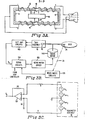
- the two coils 12 and 14 are coupled together in a bucking configuration, that is, for a magnetic field in a direction along the longitudinal axis of the coils, the output of the two coils will cancel. This is achieved, as shown in Figure 3B, by coupling the output of each coil to a differential amplifier 100 such that its common mode rejection cancels out the signals due to stray fields.
- the advantage of using a bucking configuration for the two coils is that, in addition to cancelling the noise output, the desired tachometer output from each coil is added.
- a magnetic shielding cylindrical sleeve made of a high permeability material may be used around the casing of servo motor 30, although most of the flux lines produced by the servo motor are perpendicular to the longitudinal axis of coils 12 and 14, and thus do not induce a voltage therein.
- the various parameters yield 23 mV/(inch/sec) for each coil.
- the path of the magnet within the region between the two coils is actually arcuate, but for the small angular rotation required to position head 26 between its two extreme operational positions this path substantially approximates the longitudinal axis of the tachometer assembly 10, and no correction is found necessary.
- each coil is defined by cross-section of the armature/filler subassembly, and in the preferred embodiment it substantially resembles a very thin rectangle. This has the advantage of providing a very compact and rigid structure while effectively enclosing, in combination with armature 52, substantially all the magnetic flux lines generated by magnet 16.
- FIG. 3E there is shown a block diagram illustrating the arm positioning subsystem of a disk drive.
- Tachometer magnet 16, carried in the counter weight portion 22 of actuator arm 20, is shown diagramatically being contained within tachometer assembly 10.
- the output of tachometer assembly 10 is coupled to differential amplifier 10C to produce a signal as a function of the speed of read/write head 25, as explained above.
- the speed signal thus produced is fed into servo circuit 110.
- the signals from read/write head 26 are fed to read/write circuit 120, where the embedded servo information is stripped off.
- the servo data thus produced is fed into servo circuit 110.
- Servo circuit 110 uses the velocity signal, the embedded servo signals and a selected track signal from a disk controller to generate a control signal used by servo motor driver 130 to control the operation of servo motor 140, which positions arm 20 at the selected track.
- the servo circuit 110 uses the velocity information to provide a higher servo loop bandwidth, to provide the primary servo signal while the head is seeking the next track, and to provide a secondary position signal.
- a position signal is obtained in servo circuit 110 by integrating the velocity signal.
- the velocity signal is also used to determine the arm's position when loading the head, since when the head is not loaded on the disk. and therefore not reading the recorded information, no other servo information is available.
Landscapes
- Physics & Mathematics (AREA)
- General Physics & Mathematics (AREA)
- Moving Of Heads (AREA)
- Control Of Electric Motors In General (AREA)
- Rotational Drive Of Disk (AREA)
- Supporting Of Heads In Record-Carrier Devices (AREA)
- Moving Of Head For Track Selection And Changing (AREA)
- Reciprocating, Oscillating Or Vibrating Motors (AREA)
Priority Applications (1)
| Application Number | Priority Date | Filing Date | Title |
|---|---|---|---|
| AT84401223T ATE46976T1 (de) | 1983-06-16 | 1984-06-14 | Magnetischer drehzahlmesser fuer plattenlaufwerk. |
Applications Claiming Priority (2)
| Application Number | Priority Date | Filing Date | Title |
|---|---|---|---|
| US06/505,047 US4622516A (en) | 1983-06-16 | 1983-06-16 | Magnetic tachometer for disk drives |
| US505047 | 1983-06-16 |
Publications (3)
| Publication Number | Publication Date |
|---|---|
| EP0129475A2 true EP0129475A2 (de) | 1984-12-27 |
| EP0129475A3 EP0129475A3 (en) | 1986-04-16 |
| EP0129475B1 EP0129475B1 (de) | 1989-10-04 |
Family
ID=24008781
Family Applications (1)
| Application Number | Title | Priority Date | Filing Date |
|---|---|---|---|
| EP84401223A Expired EP0129475B1 (de) | 1983-06-16 | 1984-06-14 | Magnetischer Drehzahlmesser für Plattenlaufwerk |
Country Status (7)
| Country | Link |
|---|---|
| US (1) | US4622516A (de) |
| EP (1) | EP0129475B1 (de) |
| JP (1) | JPH0792988B2 (de) |
| AT (1) | ATE46976T1 (de) |
| AU (1) | AU574683B2 (de) |
| CA (1) | CA1220549A (de) |
| DE (1) | DE3480035D1 (de) |
Families Citing this family (8)
| Publication number | Priority date | Publication date | Assignee | Title |
|---|---|---|---|---|
| JPS62119461A (ja) * | 1985-11-19 | 1987-05-30 | Toshiba Corp | 速度検出装置 |
| US4879672A (en) * | 1987-08-21 | 1989-11-07 | Control Data Corporation | Method and apparatus for testing runout velocity and acceleration on a surface |
| US4967291A (en) * | 1988-11-02 | 1990-10-30 | Miniscribe Corporation | Method and apparatus for preventing an over-velocity error condition of a hard disk drive system |
| US5016131A (en) * | 1989-04-26 | 1991-05-14 | Digital Equipment Corporation | Integral balanced-moment head positioner |
| US5050940A (en) * | 1990-02-05 | 1991-09-24 | Allied-Signal Inc. | Brake control and anti-skid system |
| US5536985A (en) * | 1994-05-09 | 1996-07-16 | General Motors Corporation | Composite armature assembly |
| US5455723A (en) * | 1994-06-02 | 1995-10-03 | International Business Machines Corporation | Method and apparatus for ramp load and unload |
| DE102009011921A1 (de) * | 2009-03-10 | 2010-09-16 | Frank Vogelsang | Einrichtung zur Verminderung des Signalrauschens |
Family Cites Families (12)
| Publication number | Priority date | Publication date | Assignee | Title |
|---|---|---|---|---|
| US3260870A (en) * | 1962-12-28 | 1966-07-12 | Ibm | Magnetic detent mechanism |
| NL6812615A (de) * | 1968-09-05 | 1970-03-09 | ||
| DE1905535A1 (de) * | 1969-02-05 | 1970-08-20 | Ver Leichtmetallwerke Gmbh | Vorrichtung zur Messung und Regelung von niedrigen Geschwindigkeiten relativ zueinander bewegter Teile |
| NL7612401A (nl) * | 1976-11-09 | 1978-05-11 | Philips Nv | Elektrisch bestuurbare draagarminrichting. |
| DE2654755A1 (de) * | 1976-12-03 | 1978-06-08 | Bosch Gmbh Robert | Induktiver impulsgeber mit drehzahlunabhaengiger impulsamplitude |
| DE2723140C2 (de) * | 1977-05-23 | 1986-06-12 | Basf Ag, 6700 Ludwigshafen | Vorrichtung zum Positionieren von Gegenständen |
| GB2023881B (en) * | 1978-05-23 | 1982-11-17 | Pioneer Electronic Corp | Linear-tracking pick-up arm drive assembly |
| JPS6035748B2 (ja) * | 1978-10-27 | 1985-08-16 | ソニー株式会社 | レコ−ドプレ−ヤ |
| US4260914A (en) * | 1979-03-28 | 1981-04-07 | Digital Equipment Corporation | Differential linear velocity transducer |
| JPS5651059A (en) * | 1979-10-01 | 1981-05-08 | Mitsubishi Electric Corp | Flexible disc device for both side type |
| US4346416A (en) * | 1980-02-29 | 1982-08-24 | Digital Equipment Corporation | Rotary actuator assembly for disk drive head positioner |
| US4456934A (en) * | 1982-05-10 | 1984-06-26 | Kollmorgen Technologies Corporation | Linear positioning system |
-
1983
- 1983-06-16 US US06/505,047 patent/US4622516A/en not_active Expired - Lifetime
-
1984
- 1984-06-01 AU AU28950/84A patent/AU574683B2/en not_active Ceased
- 1984-06-14 AT AT84401223T patent/ATE46976T1/de not_active IP Right Cessation
- 1984-06-14 EP EP84401223A patent/EP0129475B1/de not_active Expired
- 1984-06-14 DE DE8484401223T patent/DE3480035D1/de not_active Expired
- 1984-06-15 JP JP59123512A patent/JPH0792988B2/ja not_active Expired - Lifetime
- 1984-06-15 CA CA000456676A patent/CA1220549A/en not_active Expired
Also Published As
| Publication number | Publication date |
|---|---|
| AU574683B2 (en) | 1988-07-14 |
| DE3480035D1 (en) | 1989-11-09 |
| EP0129475B1 (de) | 1989-10-04 |
| EP0129475A3 (en) | 1986-04-16 |
| JPH0792988B2 (ja) | 1995-10-09 |
| US4622516A (en) | 1986-11-11 |
| JPS6069564A (ja) | 1985-04-20 |
| ATE46976T1 (de) | 1989-10-15 |
| CA1220549A (en) | 1987-04-14 |
| AU2895084A (en) | 1984-12-20 |
Similar Documents
| Publication | Publication Date | Title |
|---|---|---|
| US4145725A (en) | Electromagnetic actuator | |
| JPH0136068B2 (de) | ||
| US3816776A (en) | External magnetic field compensator | |
| US3723779A (en) | Compensated linear motor | |
| EP0129475B1 (de) | Magnetischer Drehzahlmesser für Plattenlaufwerk | |
| JPS58207859A (ja) | リニアモ−タのための可動磁石型予備負荷支持構造 | |
| US4573094A (en) | Moving magnet disc drive actuator | |
| US4006372A (en) | Transducer positioner | |
| US3526725A (en) | Electromagnetic transducer head with plural magnetic circuits,gaps and windings | |
| US3743794A (en) | Translational motion apparatus for the magnetic transducers of a disc memory | |
| US4523375A (en) | Method of manufacture for a magnetic tachometer for disk drives | |
| CA1078513A (en) | Actuator mechanism for disk storage apparatus | |
| US3334192A (en) | Cross field magnetic transducer head | |
| US3371164A (en) | Combined magnetic transducing and erase head | |
| JP2000187953A (ja) | テ―プ駆動装置のヘッド組立体 | |
| US3526728A (en) | Variable reluctance type pickup cartridge | |
| JPH0548066B2 (de) | ||
| US4425534A (en) | Linear motor velocity sensor | |
| JPH0453190Y2 (de) | ||
| US2425486A (en) | Electric phonograph | |
| JPS61116962A (ja) | リニアモ−タ | |
| JPS6289206A (ja) | 磁気ヘツド | |
| JP3194534B2 (ja) | 磁気ヘッドとその製造方法 | |
| JPS61148617A (ja) | 磁気ヘツド | |
| JPH05314683A (ja) | ボイスコイルモータ |
Legal Events
| Date | Code | Title | Description |
|---|---|---|---|
| PUAI | Public reference made under article 153(3) epc to a published international application that has entered the european phase |
Free format text: ORIGINAL CODE: 0009012 |
|
| AK | Designated contracting states |
Designated state(s): AT BE CH DE FR GB IT LI SE |
|
| PUAL | Search report despatched |
Free format text: ORIGINAL CODE: 0009013 |
|
| AK | Designated contracting states |
Kind code of ref document: A3 Designated state(s): AT BE CH DE FR GB IT LI SE |
|
| 17P | Request for examination filed |
Effective date: 19860921 |
|
| 17Q | First examination report despatched |
Effective date: 19880212 |
|
| GRAA | (expected) grant |
Free format text: ORIGINAL CODE: 0009210 |
|
| AK | Designated contracting states |
Kind code of ref document: B1 Designated state(s): AT BE CH DE FR GB IT LI SE |
|
| REF | Corresponds to: |
Ref document number: 46976 Country of ref document: AT Date of ref document: 19891015 Kind code of ref document: T |
|
| REF | Corresponds to: |
Ref document number: 3480035 Country of ref document: DE Date of ref document: 19891109 |
|
| ITF | It: translation for a ep patent filed | ||
| ET | Fr: translation filed | ||
| PLBE | No opposition filed within time limit |
Free format text: ORIGINAL CODE: 0009261 |
|
| STAA | Information on the status of an ep patent application or granted ep patent |
Free format text: STATUS: NO OPPOSITION FILED WITHIN TIME LIMIT |
|
| 26N | No opposition filed | ||
| ITTA | It: last paid annual fee | ||
| PGFP | Annual fee paid to national office [announced via postgrant information from national office to epo] |
Ref country code: DE Payment date: 19940525 Year of fee payment: 11 |
|
| PGFP | Annual fee paid to national office [announced via postgrant information from national office to epo] |
Ref country code: GB Payment date: 19940531 Year of fee payment: 11 |
|
| PGFP | Annual fee paid to national office [announced via postgrant information from national office to epo] |
Ref country code: FR Payment date: 19940916 Year of fee payment: 11 Ref country code: CH Payment date: 19940916 Year of fee payment: 11 |
|
| PGFP | Annual fee paid to national office [announced via postgrant information from national office to epo] |
Ref country code: SE Payment date: 19940920 Year of fee payment: 11 Ref country code: AT Payment date: 19940920 Year of fee payment: 11 |
|
| PGFP | Annual fee paid to national office [announced via postgrant information from national office to epo] |
Ref country code: BE Payment date: 19940929 Year of fee payment: 11 |
|
| EAL | Se: european patent in force in sweden |
Ref document number: 84401223.7 |
|
| PG25 | Lapsed in a contracting state [announced via postgrant information from national office to epo] |
Ref country code: GB Effective date: 19950614 Ref country code: AT Effective date: 19950614 |
|
| PG25 | Lapsed in a contracting state [announced via postgrant information from national office to epo] |
Ref country code: SE Effective date: 19950615 |
|
| PG25 | Lapsed in a contracting state [announced via postgrant information from national office to epo] |
Ref country code: LI Effective date: 19950630 Ref country code: CH Effective date: 19950630 Ref country code: BE Effective date: 19950630 |
|
| BERE | Be: lapsed |
Owner name: DIGITAL EQUIPMENT CORP. Effective date: 19950630 |
|
| GBPC | Gb: european patent ceased through non-payment of renewal fee |
Effective date: 19950614 |
|
| PG25 | Lapsed in a contracting state [announced via postgrant information from national office to epo] |
Ref country code: FR Effective date: 19960229 |
|
| REG | Reference to a national code |
Ref country code: CH Ref legal event code: PL |
|
| PG25 | Lapsed in a contracting state [announced via postgrant information from national office to epo] |
Ref country code: DE Effective date: 19960301 |
|
| EUG | Se: european patent has lapsed |
Ref document number: 84401223.7 |
|
| REG | Reference to a national code |
Ref country code: FR Ref legal event code: ST |