US2425486A - Electric phonograph - Google Patents
Electric phonograph Download PDFInfo
- Publication number
- US2425486A US2425486A US589109A US58910945A US2425486A US 2425486 A US2425486 A US 2425486A US 589109 A US589109 A US 589109A US 58910945 A US58910945 A US 58910945A US 2425486 A US2425486 A US 2425486A
- Authority
- US
- United States
- Prior art keywords
- armature
- magnetic circuit
- magnetic
- amplifier
- recording
- Prior art date
- Legal status (The legal status is an assumption and is not a legal conclusion. Google has not performed a legal analysis and makes no representation as to the accuracy of the status listed.)
- Expired - Lifetime
Links
Images

Classifications
-
- G—PHYSICS
- G11—INFORMATION STORAGE
- G11B—INFORMATION STORAGE BASED ON RELATIVE MOVEMENT BETWEEN RECORD CARRIER AND TRANSDUCER
- G11B25/00—Apparatus characterised by the shape of record carrier employed but not specific to the method of recording or reproducing, e.g. dictating apparatus; Combinations of such apparatus
- G11B25/02—Apparatus characterised by the shape of record carrier employed but not specific to the method of recording or reproducing, e.g. dictating apparatus; Combinations of such apparatus using cylindrical record carriers
Definitions
- This invention relates to electric phonographs and, more particularly, to an improved electromechanical translating device for use as a recorder and/or reproducer unit in such phonographs.
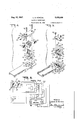
- Figure l is a cross-sectional view of a portion of an ofiice dictating machine incorporating a translating device in accordance with the present invention
- Figure 2 is a cross-section of the translating device shown in Figure 1 taken on line 2-2 thereof;
- Figure 3 is another crosssection of this translating device taken on line 33 of Figure 2;
- Figure 4 is an exploded view of the upper portion of the translating device of Figure 1;
- Figure 5 is an exploded view of the lower portion of this translating device.
- Figure 6 is a schematic wiring diagram of sound recording and reproducing apparatus incorporating a translating device in accordance with the present invention.
- FIG. 1 A portion of an office dictating machine for recording and reproducing oflice dictation is shown in Figure 1 for the purpose of illustrating this invention.
- This machine has a carriage I0 mounted on guide rods I2 and I4 supported on a frame It attached to a base IS.
- a mandrel 20, adapted to support a cylindrical sound record blank 22, is suitably rotatably mounted above the base l8 parallel to the guide rods l2 and I4.
- An electromagnetic recorder and reproducer unit, embodying the present invention and generally indicated at 24 is supported by an arm 36 which in turn is mounted on the carriage Ii] by means of a, suitable pivotal posi tioning structure incorporated therein.
- This recorder-reproducer unit 24 is encased by a cover 34 and is provided with a recording stylus 2B and a reproducing stylus 28 mounted on styli supporting arms 30 and 32, respectively, connected to the vibratory portion of the translating device 24 in the manner hereinafter to be described.
- the pivotal translating unit positioning structure which secures the supporting arm 36 to the carriage H] may be of any suitable type which permits positioning of the translating unit 24 in either record, neutral, or reproduce positions by means of a control lever 38.
- record position it is so adjusted that the recording stylus 25 coacts with the record blank 22 to permit the formation of a sound record thereon.
- reproduce position the translating unit 24 is moved into such position that the reproducing stylus 28 is moved into operative position with respect to the record blank 22 so as to permit the transcribing of a sound record therefrom.
- neutral position the translating unit 24 is moved to a position intermediate these record and reproduce positions, in which position both styli of the translating device 24 are removed from operative contact with the record blank 22 to permit the record to be removed and replaced.
- this pivotal support structure in carriage I 0 is arranged to permit motion of the translating unit 24 in only one plane, i. e., toward and away from the record tablet 22, when in record position; but to permit motion of the translating unit 24 in two directions, 1. e., axially along the surface of the record tablet 22 as well as toward and away from the record tablet, when in reproduce position, so that the reproducing stylus 28 is free to follow a recorded sound groove.
- the control lever 38 is pivotally mounted on the carriage IE) to pivot around the axis of the guide rod I4.
- the usual mechanism is also provided for progressively moving the carriage IIJ along the surface of the record 22 so that the recording stylus 26 may cut a spiral sound groove thereon, or the,
- reproducin stylus 28 may follow such a spiral sound groove previously cut. This is accomplished by means of a feed screw 42 rotatably supported on the frame I6 and preferably driven by the same motor 'which drives the mandrel 20.
- A' cam 50 mounted on the control lever 38 is provided for temporarily disengaging the feed nut 44 from the feed screw 42 .when the translating device ,24 is in neutral position, This cam 50 coacts with a cam follower lever 52 pivotally mounted on the carriage ID to rotate the pivoted arm 46 to move the feed nut 44 away from the feedscrew 42.
- Apparatus for accomplishin all of the functions justdescribed may be any suitable, apparatus, such, for example, as that shown in U. S. Patent No. 2,143,819 to Leland D. Norton, and willnot be further described herein because such apparatus per se does not form a portion of thepresent invention.
- the yoke 58 forms the back portion, and the permanent magnets 62 and the pole pieces 66 and 68 form the outside arms of the E-shaped magnetic circuit structure.
- the center arm of this E-shaped structure is formed I2, each made of a stack of laminations of highly 7 permeable magnetic sheet material.
- One end of each of these core members I0 and I2 is square and is adapted to fit in a slot I4 of comparable dimensions cut in the under surface of the yoke 58.
- the free ends of these core pieces terminate in the form of isosceles prisms, the vertex edges of which are rounded to cylindrical surfaces as shown.
- central magnetic cores I6 and I2 are held in position against the yoke 58 with their ends intermediate the pole pieces 66 and 66 by four blocks I6 of non-magnetic material positioned between the sloping faces of the central cores I6 and i2 and sloping surfaces 6? and 69 on the inner ends of pole pieces 66 and 68, respectively-
- the cylindrical tips of these central magnetic cores I0 and Y2 are so dimensioned as to extend between and beyond the lower surfaces spectively, whereby voltages related to flux varia- V tions in the magnetic circuit can be impressed on or derived from the translating device24.
- terminaI strip of insulating material 82 is fas tened by two screws 84 to one end of the yoke 58 and is provided with two pairs of terminals 86 and 88, to which are connected the ends of coils l8 and 80, respectively. All of these parts of the translating device are encased in a housing 34 as shown in Figure 1. r I
- the armature portion of this electromagnetic translating device comprises two rectangular ,armatures of magnetic material. 90 and 92 arranged to pivot about a, resilient axis and see-saw on the tips of the central cores I0 and '72, complish this, these armature pieces 90 and92 are secured in spaced relation to the one side of a strip 94 of resilient material such, for example, as phosphor bronze, which can be seen indetail in Figure 5, by means of two pairs of rivets 96 and 98, respectively. These rivets also secure two stylus supporting plates Hi0 and I02, carrying the stylus supporting arms 30 and 32, respectively, to which in turn are secured the recording stylus 26 and reproducing stylus 28, respectively, to the armature elements 96 and 9 2, respectively.
- This resilient strip 94 is secured to the supporting plate 36 by two screws I64 and I96 which pass through holes in either end of the strip 94 and are threaded into pillar blocks I08 and H6 secured to the underside of the supporting plate 36 as shown in Figure 5.
- the central portion of resilient strip 94 intermediate the two armatures 99 and 92 is also secured to the support plate 36 by means of a screw I I2 passing through a hole in the center of the strip 94 and threaded into a pillar block I I4 positioned between the two rectangular slots 54 and 56 in the supporting plate 36.
- Pillar blocks I08, H0 and H4 are all of equal height, just sufficient to press the undersides of armatures 90 and 92 firmly against the cylindrical ends of the central core members I0 and I2, so that the armatures can see-saw on the ends of these core members, as is shown more clearly in Figure 3.
- the resilient strip 94 acts as a torsion-bar support or a resilient pivotal axis for the armatures 90 and 92.
- the screws I04 and I66 also hold a casing I I6 which completely covers this armature assembly so that only the styli supporting arms 30 and 32 project therefrom through slots H8 and I20, respectively, as shown in Figure 5.
- this casing H6 is not shown in any of the other figures of the drawings.
- the amount that the central core portions I0 and I2 project beyond the pole pieces 66 and 68 determines the length of the air ap between the ends of the armatures 90 and 92 and the pole pieces 66 and 68, respectively. This has been shown in an exaggerated amount in Figure 3, but in actual operation it has been determined that an extension of the central core portions III and 12 of about four or five thousandths of an inch beyond the bottom surfaces of the pole pieces 66 and 68 provides a satisfactory air gap for efiicient operation.
- the stiffness or compliance characteristics of the translating device may be controlled by controlling the stiffness characteristics of the resilient strip 94, both by suitable choice of its composition and of its dimensions.
- the magnetic structure of the electromagnetic recorder and reproducer unit 24 just described has a yoke 58 and two permanent magnets 62 common to both the recorder and reproducer portions of the unit, but four separate pole pieces 66 and 68 having two separate armatures 90 and 92 spanning the air gaps between these pole pieces and see-sawing on the central core members Ill and 12, each of which is surrounded by a separate winding I8 and 80, thus providing separate coils and vibratory systems for recording and reproducing.
- this signal sets up a magnetic field in the central core I0 which aids or opposes the magnetic flux produced in the circuit by the permanent magnets 62 and causes one end of the armature 90 pivoted on the end of this core If! to be attracted to one of the pole pieces 66 while the other end of the armature I0 is repelled by the other pole piece 56.
- This alternate attraction and repulsion will occur in accordance with the variations of the signal impressed on the winding 18, thus causing the recording stylus 26 to follow the movements of the armature 9D and form a sound groove on the surface of the record 22.
- the conditioning lever 38 When the conditioning lever 38 is thrown to reproduce position, moving the reproducing stylus 28 into contact with a sound groove recorded on the surface of a record blank 22, the movement of the reproducing armature 92 as it see-saws about the end of the central core element I2 in response to movements of the reproducing stylus 28 in the record groove, decreases the air gap between one end of the armature 92 and one of the pole pieces 68 while it increases the air gap between the other end of this armature 92 and the other pole piece 68, thus maintaining a uniform reluctance path from one pole piece 68 to the other but disturbing the flux balance between the pole pieces 68 and the central core 12 so that there is an alternation of the magnetic flux passing through the central core piece I2.
- This induces a corresponding voltage in reproducing coil 80 which surrounds this central core 12 and thus provides a signal corresponding to the undulations of the sound record groove on record tablet 22.
- this structure with its separate, but closely adjacent, coils I8 and 8B permits the use of novel and advantageous circuit arrangements such as that shown in Figure 6 in which, on recording, the reproducing coil may be connected into the recording amplifier circuit in such a manner as to provide a desirable amount of degenerative feedback encompassing not only the recording amplifier but also portions of the translating device itself to provide more desirable response characteristics; and which, when the apparatus is conditioned for reproducing, permits the recording winding I8 to be connected in a circuit in such a manner as tocancel out all parasitic voltage pickups in the reproducing coil caused by changes in magnetic fields external to the translating device itself. This is accomplished with the circuit arrangement shown in Figure 6.
- the recorder winding I8 and the reproducer winding 80 are connected through terminals 88 and 88, respectively, to the central poles of a four pole double-throw switch, generally indicated at I336.
- the other eight terminals of this switch I311 are connected as shown in Figure 6 to the input and output circuits of an electronic tube amplifier, generally indicated at I32, through a double-pole double-throw amplifier-reversing switch I34 which is also connected to a microphone-loudspeaker or transducer device I35.
- the contacts of the amplifier reversing switch I34 are preferably shielded from each other to prevent feedback from the output to the input terminals of th amplifier I32.
- this switch I34 may be separate from switch I30, it is preferably operated simultaneously therewith as switch I30 is moved to either record or reproduce position, as shown in Figure 6. If desired, these switches may be connected with the control lever 38 on carriage I0 so that the switches are operated in the desired direction by operation of this control lever.
- recorder winding I8 is connected to the output of amplifier I32
- transducer I36 is connected as a microphone to the input of amplifier I32
- reproducer winding 80 is connected to feedback terminals I38 on amplifier I32, suitably connected, as is well known in the art, so that a degenerative feedback effect is produced in the amplifier to provide a more uniform output characteristic.
- reproducer winding 89 is connected in a series bucking arrangement with recorder winding I8 to the input of amplifier I32 and transducer I36 is connected as a loudspeaker to the output of the amplifier I32.
- the recorder windin I8 acts to pick up any stray fields in the neighborhood of the translating device 24 which would also be picked up by the reproducer winding 80 and cause the effect of these stray fields to be cancelled out, for example, as described in U. S. Patent No. 2,275,309 to Leland D. Norton.
- an electro-mechanical translating device comprising, in combination, means form- 7 ing an E-shaped magnetic circuit having air gaps therein between the pole pieces formed by the free ends of the outer arms of said E and the middle arm of said E, a strip of resilient material supported at its ends perpendicular to said E-shaped magnetic circuit means near the free end of the middle arm thereof, an armature extending from one of said pole pieces to the other and mounted on said strip of resilient material to see-saw on the free end of the middle arm of said 'E-shaped magnetic circuit means to oppositely vary the lengths of the air gaps between said pole pieces and said middle arm, means providing a magnetic flux in said magnetic circuit means, inductive means surrounding a portion of said magnetic circuit to carry an electric current which is a function of the change in magnetic flux in said magnetic circuit means, and stylusmeans attached to said armature for coacting with a sound record medium.
- an electro-mecham'cal translating device comprising, in combination, means forming an E-shaped magnetic circuit having air gaps therein between the pole pieces formed by the free ends of the outer arms of said E and the middle arm of said E, a strip of resilient nonmagnetic material supported at its ends perpen dicular to said E-shaped magnetic circuit means nearthe free end Of the middle arm thereof, an armature extending from one of said pole pieces to the other and mounted on said strip of resilient material to see-saw on the free end of the middle arm of said E-shaped magnetic circuit means to oppositely vary the lengths of the air gaps between said pole pieces and said middle arm, means providing a magnetic flux in said magnetic circuit means, inductive means surrounding a portion of said magnetic circuit to -carry an electric current which is a function of the change in magnetic flux in said magnetic circuit means, and stylus means attached to said armature for coacting with a sound record medium.
- an electro-mechanical translating device for use in sound recording and reproducing systems, means forming an E-shaped' magnetic circuit having air gaps therein between the pole pieces formed by the free'ends of the outer arms of said E and the middle arm of said E, said middle arm terminating in a cylindrical surface the axis of which is perpendicular to said E.-shaped magnetic circuit means, a strip of resilient material supported at its ends adjacent and parallel to said cylindrical surface on the free end of said middle arm, an armature extending from one of said pole pieces to theother and mounted on said strip of resilient material to see-saw on the free end of the middle arm of said E-shaped magnetic circuit means to oppositely vary the lengths of the air gaps between said pole pieces and the ends of said'armature, said resilient strip holding said armature in line contact with said middle arm along lines forming elements of said cylindrical surface, meansproviding a magnetic flux in said magnetic circuit means, inductive means surrounding a portion of said-magnetic circuit to carry an electric current which is a function
- an 'electro-mechanical translating device comprising, in combination, means forming an E-shaped magnetic circuit having airgaps therein between the'pole faces formed by the free ends of the outer arms of said E and the free end of the middle arm of said E, said middle arm projectingfthrough the plane of said pole faces by an amount equal to the operating air tive means surrounding a portion of said magnetic circuit to carry an electric current'which is a function of the'change in magnetic flux'in said magnetic circuit means, and stylus means attached to said armature for coacting with a sound record medium.
- an electro-mechanical translating de vice comprising, in combination, means forming an E-shaped magnetic circuit having air gaps therein between the pole piecesformed by the free ends of the outer arms of said E and the middle arm of said E, a strip of resilient materal supported at its ends perpendicular to said E-shaped magnetic circuit'means near the'iree end of the middle arm thereof, an armature extending from one of said pole pieces to the other and mounted on said strip ofresilient material 7 to see-saw on the free end of the middle arm of to said armature for coacting with a sound rec- 0rd medium.
- an electro-mechanical"translating as: vice comprising, in combination; E-shaped mag-' netic circuit means having air gaps therein between the pole pieces formed by the freeends of the outer arms of said E and the middle arm 7 of said E, portions of the free ends of the arms of said E-shaped means being bifurcated to provide two parallel E-shaped magnetic circuits having common portions but separate poles in parallel planes, a strip of resilient materialarranged to bridge the free ends of the middle arms of said 'E-shaped magnetic circuit means and supported at its ends and at its central portionbe5 f tween the pole faces of the middle arms of'said E-shaped circuits, two armatures each mounted on said strip of resilient material to see-saw on the free end of one of said middle arms of said E-shaped' magnetic circuit means and each extending from its respective pole piece on one side of its middle arm to the corresponding pole piece on the other side thereof, means providing a magnetic flux in both of said magnetic circuits, inductive means associated
- an electro-mechanical translating device comprising, in combination, E-shaped magnetic circuit means having air gaps therein between the pole pieces formed by the free ends of the outer arms of said E and the middle arm of said E, portions of the free ends of the arms of said E-shaped means being bifurcated to provide two parallel E-shaped magnetic circuits having common portions but separate poles in parallel planes, a strip of resilient material arranged to bridge the free ends of the middle arms of said E-shaped magnetic circuit means and supported at its ends and at its central portion between the pole pieces of the middle arms of said E-shaped circuits, two armatures each mounted on said strip of resilient material to see-saw on the free end of one of said middle arms of said E-shaped magnetic circuit means and each extending from'its respective pole piece on one side of its middle arm to the corresponding pole piece on the other side thereof, means providing a magnetic flux in both of said magnetic circuits, two coils each surrounding-one of the bifurcated portions of said middle arm for carrying electriccurrents related
- an electro-mechanical translating device comprising, in combination, E-shaped magnetic circuit means having air gaps therein between the pole pieces formed by the free ends of the outer arms of said 5 and the middle arm of said E, portions of the free ends of the arms of said E-shaped means beingbifurcated to provide two parallel E-shaped magnetic circuits having common portions but separate poles in parallel planes, a strip of resilient material arranged to bridge the freeends of the middle arms-of said E-shaped magnetic circuitlmeans and supported at its ends and at its central portion between the pole pieces of the middle arms of said E-shaped circuits, a permanent magnet in each of the outer arms of said magnetic circuit means, said magnets being oppositely polarized to provide a magnetic flux around both of said magnetic circuits, two armatures-eachmounted on said strip of resilient material to see-saw on the free end of one of said middle arms of said E- shaped magnetic circuit means and each extending from its respective-pole piece on one side of its middle arm to
- an electro-mechan-ical translating -device comprising, in combination, -E-shaped mag- 10 netic circuit means having air gaps therein between the pole pieces formed by the free ends of the outer arms of said E and'the middle arm of said E, portions of the free ends of the arms of said E-shaped means being bifurcated to provide two parallel E-shaped magneticcircuitshaving common portions but separate poles in parallel planes, a strip of resilientmaterial arranged to bridge the free ends of the middle arms of said E-shaped magnetic circuit means and supported at its ends and at its central portion between the pole pieces of the middle arms of said E- shaped'circuits, two armatures each mounted on said strip of resilient material to see-saw on the free end of one of said middle arms of said E-shapedmagnetic circuit means and each extending from its respective pole piece on one side of its middle arm to the corresponding polepiece on the other side thereof, said resilient strip having portions of predetermined reduced cross-section on both sides of each of said armatures to
- an electro-mechanical translating .device, .C0mprising,'in combination E-shaped magnetic circuit means having air gaps therein betweenthe pole pieces formed by the free ends of the outer armsof said E and the middle arm of said E, portions of the free ends of the arms of said E-shaped means beinglbiiurcated, to provide two parallel E-shaped magnetic circuits having common portions but separate poles in parallelplanes, a strip of resilient material arranged to bridge the free ends of the-middle arms of said E-shaped magnetic circuit means and supported atiits ends and at its central portion be tween the pole pieces of the middlearms of said E-shaped circuits, first and-second armatureseach mounted on said strip of resilient material to seesaw on the freeend of onesof said middle arms of sai E-shaped magnetic circuit means and each extending from its respective pole piece on one side of its middle arm to the corresponding pole piece on the other side-thereof, means providing a magnetic flux in :
- an electro-mechanical translating device including :magnetic circuit means having common portions providinga polarizing 'magnetic flux and bifurcated portions providing two separate sets ofpoles and air gaps in parallel planes, first and second armatures each mounted to vibrate with changes in magnetic 'flux through one of said sets of poles and air gaps, a recording stylus attached to said first armature, a reproducin stylus attached to said second armature, a first coil wound around the one of said bifurcated portions of said magnetic circuit means associated with said first armature and adapted to be connected to a source of signals to be recorded to produce in its magnetic circuit a flux varying,,with said signal to move said first arma ture therewith, a second coil Wound around the other of said bifurcated portions of said magnetic circuit means responsive to variations of the flux in its magnetic circuit caused by movement of said second armature to generate a voltage Varying with a recorded signal, an electron tube amplifier having input and output circuit
- an electron tube amplifier having input and output circuits, a transducer unit, means connecting said second coil to the input circuit of said amplifier, means connecting said transducer unit to the output circuit of said amplifier, and means connecting said first coil in series opposition with said second coil whereby stray magneticfields picked up by said coils are canceled out.
- an electro-mechani ical translating device including magnetic circuit means having common portions providing a polarizing magnetic fiuX and bifurcated portions providing two separate sets of poles and air gaps in parallel planes, first and second armatures each mounted to vibrate with changesin magnetic flux through one of said sets of poles and air gaps, a recording stylus attached to said first armature, a reproducing stylus attached .to said second armature, mechanical means for selectively positioning said recording stylus or said reproducing stylus in operative relationship to a record medium a first coil wound around the one of said bifurcated portions of said magnetic circuit means associated withsaid first armature and adapted to beconnected to a source of si circuit a flux varying with said signal to move said first armature therewith, a second coil wound around the other of said bifurcated portions of said magnetic circuit means responsive'to' variations of the flux in its magnetic circuit caused by movement of said second armature to generate a voltage varying with a
- anelectro mechanical translating device comprising, in combination, E-shaped magnetic circuit means having air gaps therein between the pole pieces formed by the free ends of the outer arms of said E and the middle arm of said E, portions of the free ends of the arms of said E-shaped means being bifurcated to provicle two parallel E-shaped magnetic circuit having common portions but separate polesin parallel planes, a strip of resilient material arranged to bridge the free ends of the middle arms of said E-shaped magnetic circuit means and supported at its ends and at its central portion between the pole pieces of the middle arms of said E-shape'd tached to said first armature, a reproducing stylus attached to said second armature mechanical means for selectively positioning said recording stylus or said reproducing stylus in operative re- 7 lationship to a record medium, means providing a polarizingmagnetic flux in both of said mag-' netic circuits, a first coil wound around oneof the bifurcated portions of the middle arm associated with
- an electro-mechanical translating device including two magnetic circuit means each having polarizing flux means and separate sets of poles and air gaps, first and second armatures each mounted to vibrate with changes in magnetic fiux through one of said sets of poles and air gaps, a recording stylus attached to said first armature, a reproducing stylus attached to said second armature, a first coil associated with the one of said magnetic circuit means coacting with said first armature and adapted to be connected to a source of signals to be recorded to produce in its magnetic circuit a fiux varying with said signal to move said first armature therewith, a second coil associated with the other of said magnetic circuit means responsive to variations of the fiuX in its magnetic circuit caused by movement of said second armature to generate a voltage varying with a recorded signal, an electron tube amplifier having input and output circuits and terminals for applying a degenerative feedback voltage to said amplifier, a source of signals to be recorded connected to the input circuit of said amplifier, means connecting said first coil
- an electro-mechanical translating device including two magnetic circuit means each having polarizing fiux means and separate sets of poles and air gaps, first and second armatures each mounted to vibrate with changes in magnetic flux through one of said sets of poles and air gaps, a recording stylus attached to said first armature, a reproducing stylus attached to said second armature, a first coil associated with the one of said magnetic circuit means coacting with said first armature and adapted to be connected to a source of signals to be recorded to produce in its magnetic circuit a fiux varying with said signa1 to move said first armature therewith, a second cog] associated with the other of said magnetic circuit means responsive to variations of the flux in its magnetic circuit caused by movement of said second armature to generate a voltage Varying with a recorded signal, an electron tube amplifier having input and output circuits, a transducer unit, means connecting said second coil to the input circuit of said amplifier, means connecting said transducer unit to the output circuit of said amplifier
- an electro-mechanical translating device including tWo magnetic circuit means each having polarizing fiux means and separate sets of poles and air gaps, first and second armatures each mounted to vibrate with changes in magnetic flux through one of said sets of poles and air gaps, a recording stylus attached to said first armature, a reproducing stylus attached to said second armature, means for selectively positioning said recording stylus or said reproducing stylus in operative relationship to a record medium, a first coil associated with the one of said magnetic circuit means coacting with said first armature and adapted to be connected to a source of signals to be recorded to produce in its magnetic circuit a flux varying with said signal to move said first armature therewith, a second coil associated with the other of said magnetic circuit means responsive to Variations of the flux in its magnetic circuit caused by movement of said second armature to generate a voltage varying with a recorded signal, an electron tube amplifier having input and output circuits and terminals for applying a degenerative feedback voltage
Landscapes
- Magnetic Heads (AREA)
Description
1947-. D. NO'RTON 2,425,486
ELECTRIC PHONOGRAPH I Filed April 19, 1945 2 Sheets-Sheet l I Reproduce Neutral INVVENTORI Leland l1 NOI'Z'OI? ATTOR Aug 12, 1947.
L. D. NORTON rnonoemrn Filed April 19, 1945 ELECTRIC 2 Sheets-Shet 2 Feedbclk Connection INVENTOR Leldrzd D. Nort on I Patented Aug. 12, 1947 ELECTRIC PHONOGRAPH Leland D. Norton, Fairfield, Conn., assignor to Dictaphone Corporation, New York, N. Y., a corporation of New York Application April 19, 1945, Serial No. 589,109
17 Claims.
This invention relates to electric phonographs and, more particularly, to an improved electromechanical translating device for use as a recorder and/or reproducer unit in such phonographs.
It is an object of this invention to provide an improved electro-mechanical translating device of great simplicity and high efliciency for use as a recorder and/or reproducer unit in sound recording apparatus, and especially for use in such apparatus designed for office dictation and transcription.
It is a further object of this invention to provide such a translating device of improved and simplified construction such that an entire unit may be contained in small space, and one in which portions of separate recording and reproducing elements are combined to do double duty, thus forming a combination unit of simplified construction and of size comparable to that of a single one of such elements.
It is an additional object of this invention to provide a recorder and reproducer translating device of such construction as to permit it to be used in a sound recording and reproducing apparatus incorporating the features of external hum pickup compensation when reproducing, and amplifier degenerative feedback operation when recording, to provide a desired recording response characteristic, and to permit these features to be used without the need for any additional parts in the recorder-reproducer unit.
These and other apparent objects and advantages of this invention are obtained by the means described in the following specification and may be more readily understood by reference to the accompanying drawings wherein:
Figure l is a cross-sectional view of a portion of an ofiice dictating machine incorporating a translating device in accordance with the present invention;
Figure 2 is a cross-section of the translating device shown in Figure 1 taken on line 2-2 thereof;
Figure 3 is another crosssection of this translating device taken on line 33 of Figure 2;
Figure 4 is an exploded view of the upper portion of the translating device of Figure 1;
Figure 5 is an exploded view of the lower portion of this translating device; and
Figure 6 is a schematic wiring diagram of sound recording and reproducing apparatus incorporating a translating device in accordance with the present invention.
A portion of an office dictating machine for recording and reproducing oflice dictation is shown in Figure 1 for the purpose of illustrating this invention. This machine has a carriage I0 mounted on guide rods I2 and I4 supported on a frame It attached to a base IS.
A mandrel 20, adapted to support a cylindrical sound record blank 22, is suitably rotatably mounted above the base l8 parallel to the guide rods l2 and I4. An electromagnetic recorder and reproducer unit, embodying the present invention and generally indicated at 24 is supported by an arm 36 which in turn is mounted on the carriage Ii] by means of a, suitable pivotal posi tioning structure incorporated therein. This recorder-reproducer unit 24 is encased by a cover 34 and is provided with a recording stylus 2B and a reproducing stylus 28 mounted on styli supporting arms 30 and 32, respectively, connected to the vibratory portion of the translating device 24 in the manner hereinafter to be described. The pivotal translating unit positioning structure, which secures the supporting arm 36 to the carriage H], may be of any suitable type which permits positioning of the translating unit 24 in either record, neutral, or reproduce positions by means of a control lever 38. In record position it is so adjusted that the recording stylus 25 coacts with the record blank 22 to permit the formation of a sound record thereon. In reproduce position the translating unit 24 is moved into such position that the reproducing stylus 28 is moved into operative position with respect to the record blank 22 so as to permit the transcribing of a sound record therefrom. In neutral position the translating unit 24 is moved to a position intermediate these record and reproduce positions, in which position both styli of the translating device 24 are removed from operative contact with the record blank 22 to permit the record to be removed and replaced. In addition, this pivotal support structure in carriage I 0 is arranged to permit motion of the translating unit 24 in only one plane, i. e., toward and away from the record tablet 22, when in record position; but to permit motion of the translating unit 24 in two directions, 1. e., axially along the surface of the record tablet 22 as well as toward and away from the record tablet, when in reproduce position, so that the reproducing stylus 28 is free to follow a recorded sound groove. The control lever 38 is pivotally mounted on the carriage IE) to pivot around the axis of the guide rod I4. When this control lever 38 is in the position shown in Figure 1 the translating device is positioned for recording with the recording leader ball arrangement 21 is provided for determining the average depth of the groove formed in the record blank 22'by the recording stylus 26 and this groove depth may beset by means of an adjustment screw 29. r
The usual mechanism is also provided for progressively moving the carriage IIJ along the surface of the record 22 so that the recording stylus 26 may cut a spiral sound groove thereon, or the,
reproducin stylus 28 may follow such a spiral sound groove previously cut. This is accomplished by means of a feed screw 42 rotatably supported on the frame I6 and preferably driven by the same motor 'which drives the mandrel 20. A feed nut 44, pivotally mounted on a pivoted arm, 46 attached to the carriage I and normally held against the feed screw 42 by means of a spring 48, supplies the driving connection between this feed screw 42 and the carriage ID. A' cam 50 mounted on the control lever 38, is provided for temporarily disengaging the feed nut 44 from the feed screw 42 .when the translating device ,24 is in neutral position, This cam 50 coacts with a cam follower lever 52 pivotally mounted on the carriage ID to rotate the pivoted arm 46 to move the feed nut 44 away from the feedscrew 42. Apparatus for accomplishin all of the functions justdescribed may be any suitable, apparatus, such, for example, as that shown in U. S. Patent No. 2,143,819 to Leland D. Norton, and willnot be further described herein because such apparatus per se does not form a portion of thepresent invention The electromagnetic recording and reproducing,
terminaI strip of insulating material 82 is fas tened by two screws 84 to one end of the yoke 58 and is provided with two pairs of terminals 86 and 88, to which are connected the ends of coils l8 and 80, respectively. All of these parts of the translating device are encased in a housing 34 as shown in Figure 1. r I
The armature portion of this electromagnetic translating device comprises two rectangular ,armatures of magnetic material. 90 and 92 arranged to pivot about a, resilient axis and see-saw on the tips of the central cores I0 and '72, complish this, these armature pieces 90 and92 are secured in spaced relation to the one side of a strip 94 of resilient material such, for example, as phosphor bronze, which can be seen indetail in Figure 5, by means of two pairs of rivets 96 and 98, respectively. These rivets also secure two stylus supporting plates Hi0 and I02, carrying the stylus supporting arms 30 and 32, respectively, to which in turn are secured the recording stylus 26 and reproducing stylus 28, respectively, to the armature elements 96 and 9 2, respectively. This resilient strip 94 is secured to the supporting plate 36 by two screws I64 and I96 which pass through holes in either end of the strip 94 and are threaded into pillar blocks I08 and H6 secured to the underside of the supporting plate 36 as shown in Figure 5. The central portion of resilient strip 94 intermediate the two armatures 99 and 92 is also secured to the support plate 36 by means of a screw I I2 passing through a hole in the center of the strip 94 and threaded into a pillar block I I4 positioned between the two rectangular slots 54 and 56 in the supporting plate 36. Pillar blocks I08, H0 and H4 are all of equal height, just sufficient to press the undersides of armatures 90 and 92 firmly against the cylindrical ends of the central core members I0 and I2, so that the armatures can see-saw on the ends of these core members, as is shown more clearly in Figure 3.
Thus it can be seen that the resilient strip 94 acts as a torsion-bar support or a resilient pivotal axis for the armatures 90 and 92. As shown in Figure 5, the screws I04 and I66 also hold a casing I I6 which completely covers this armature assembly so that only the styli supporting arms 30 and 32 project therefrom through slots H8 and I20, respectively, as shown in Figure 5. For purposes of simplicity, this casing H6 is not shown in any of the other figures of the drawings.
As mentioned above, the amount that the central core portions I0 and I2 project beyond the pole pieces 66 and 68 determines the length of the air ap between the ends of the armatures 90 and 92 and the pole pieces 66 and 68, respectively. This has been shown in an exaggerated amount in Figure 3, but in actual operation it has been determined that an extension of the central core portions III and 12 of about four or five thousandths of an inch beyond the bottom surfaces of the pole pieces 66 and 68 provides a satisfactory air gap for efiicient operation. Further, the stiffness or compliance characteristics of the translating device may be controlled by controlling the stiffness characteristics of the resilient strip 94, both by suitable choice of its composition and of its dimensions. In addition, its stiffness can be controlled by cutting slots therein in the manner shown at I22, I24, I26 and I28 in Figure 5. By providing a difierent depth for these slots adjacent the recorder armature with respect to those adjacent the reproducer armature, the compliance of the translating device when operating as a recorder may be made different from its compliance when operating as a reproducer.
It can be seen that the magnetic structure of the electromagnetic recorder and reproducer unit 24 just described has a yoke 58 and two permanent magnets 62 common to both the recorder and reproducer portions of the unit, but four separate pole pieces 66 and 68 having two separate armatures 90 and 92 spanning the air gaps between these pole pieces and see-sawing on the central core members Ill and 12, each of which is surrounded by a separate winding I8 and 80, thus providing separate coils and vibratory systems for recording and reproducing.
With the translating device herein described,
when a signal to be recorded is applied to the recording coil I8, this signal sets up a magnetic field in the central core I0 which aids or opposes the magnetic flux produced in the circuit by the permanent magnets 62 and causes one end of the armature 90 pivoted on the end of this core If! to be attracted to one of the pole pieces 66 while the other end of the armature I0 is repelled by the other pole piece 56. This alternate attraction and repulsion will occur in accordance with the variations of the signal impressed on the winding 18, thus causing the recording stylus 26 to follow the movements of the armature 9D and form a sound groove on the surface of the record 22. When the conditioning lever 38 is thrown to reproduce position, moving the reproducing stylus 28 into contact with a sound groove recorded on the surface of a record blank 22, the movement of the reproducing armature 92 as it see-saws about the end of the central core element I2 in response to movements of the reproducing stylus 28 in the record groove, decreases the air gap between one end of the armature 92 and one of the pole pieces 68 while it increases the air gap between the other end of this armature 92 and the other pole piece 68, thus maintaining a uniform reluctance path from one pole piece 68 to the other but disturbing the flux balance between the pole pieces 68 and the central core 12 so that there is an alternation of the magnetic flux passing through the central core piece I2. This, in turn, induces a corresponding voltage in reproducing coil 80 which surrounds this central core 12 and thus provides a signal corresponding to the undulations of the sound record groove on record tablet 22.
In addition to providing a compact and highly efiicient recording and reproducing translating device, this structure with its separate, but closely adjacent, coils I8 and 8B permits the use of novel and advantageous circuit arrangements such as that shown in Figure 6 in which, on recording, the reproducing coil may be connected into the recording amplifier circuit in such a manner as to provide a desirable amount of degenerative feedback encompassing not only the recording amplifier but also portions of the translating device itself to provide more desirable response characteristics; and which, when the apparatus is conditioned for reproducing, permits the recording winding I8 to be connected in a circuit in such a manner as tocancel out all parasitic voltage pickups in the reproducing coil caused by changes in magnetic fields external to the translating device itself. This is accomplished with the circuit arrangement shown in Figure 6. The recorder winding I8 and the reproducer winding 80 are connected through terminals 88 and 88, respectively, to the central poles of a four pole double-throw switch, generally indicated at I336. The other eight terminals of this switch I311 are connected as shown in Figure 6 to the input and output circuits of an electronic tube amplifier, generally indicated at I32, through a double-pole double-throw amplifier-reversing switch I34 which is also connected to a microphone-loudspeaker or transducer device I35. The contacts of the amplifier reversing switch I34 are preferably shielded from each other to prevent feedback from the output to the input terminals of th amplifier I32. Although this switch I34 may be separate from switch I30, it is preferably operated simultaneously therewith as switch I30 is moved to either record or reproduce position, as shown in Figure 6. If desired, these switches may be connected with the control lever 38 on carriage I0 so that the switches are operated in the desired direction by operation of this control lever. As can be readily seen by reference to Figure 6, when switches I 30 and I34 are thrown to their right-hand or record position, recorder winding I8 is connected to the output of amplifier I32, transducer I36 is connected as a microphone to the input of amplifier I32, and reproducer winding 80 is connected to feedback terminals I38 on amplifier I32, suitably connected, as is well known in the art, so that a degenerative feedback effect is produced in the amplifier to provide a more uniform output characteristic. When the switches I30 and l34 are thrown into their left-hand or reproduce position, reproducer winding 89 is connected in a series bucking arrangement with recorder winding I8 to the input of amplifier I32 and transducer I36 is connected as a loudspeaker to the output of the amplifier I32. With this connection, the recorder windin I8 acts to pick up any stray fields in the neighborhood of the translating device 24 which would also be picked up by the reproducer winding 80 and cause the effect of these stray fields to be cancelled out, for example, as described in U. S. Patent No. 2,275,309 to Leland D. Norton.
As many possible embodiments may be made of the above invention and as many changes might be made in the embodiments above set forth without departing from the scope thereof. it is to be understood that all matter hereinbefore 7 set forth or shown in the accompanying drawings is to be interpreted as illustratiVe only and not in a limiting sense.
I claim. 7 I 1. For use in sound recording and reproducing systems, an electro-mechanical translating device, comprising, in combination, means form- 7 ing an E-shaped magnetic circuit having air gaps therein between the pole pieces formed by the free ends of the outer arms of said E and the middle arm of said E, a strip of resilient material supported at its ends perpendicular to said E-shaped magnetic circuit means near the free end of the middle arm thereof, an armature extending from one of said pole pieces to the other and mounted on said strip of resilient material to see-saw on the free end of the middle arm of said 'E-shaped magnetic circuit means to oppositely vary the lengths of the air gaps between said pole pieces and said middle arm, means providing a magnetic flux in said magnetic circuit means, inductive means surrounding a portion of said magnetic circuit to carry an electric current which is a function of the change in magnetic flux in said magnetic circuit means, and stylusmeans attached to said armature for coacting with a sound record medium.
2. For use in sound recording and reproducing systems an electro-mecham'cal translating device, comprising, in combination, means forming an E-shaped magnetic circuit having air gaps therein between the pole pieces formed by the free ends of the outer arms of said E and the middle arm of said E, a strip of resilient nonmagnetic material supported at its ends perpen dicular to said E-shaped magnetic circuit means nearthe free end Of the middle arm thereof, an armature extending from one of said pole pieces to the other and mounted on said strip of resilient material to see-saw on the free end of the middle arm of said E-shaped magnetic circuit means to oppositely vary the lengths of the air gaps between said pole pieces and said middle arm, means providing a magnetic flux in said magnetic circuit means, inductive means surrounding a portion of said magnetic circuit to -carry an electric current which is a function of the change in magnetic flux in said magnetic circuit means, and stylus means attached to said armature for coacting with a sound record medium.
3. For use in sound recording and reproducing systems, an electro-mechanical translating device,'comprising, in combination, means forming an E-shaped' magnetic circuit having air gaps therein between the pole pieces formed by the free'ends of the outer arms of said E and the middle arm of said E, said middle arm terminating in a cylindrical surface the axis of which is perpendicular to said E.-shaped magnetic circuit means, a strip of resilient material supported at its ends adjacent and parallel to said cylindrical surface on the free end of said middle arm, an armature extending from one of said pole pieces to theother and mounted on said strip of resilient material to see-saw on the free end of the middle arm of said E-shaped magnetic circuit means to oppositely vary the lengths of the air gaps between said pole pieces and the ends of said'armature, said resilient strip holding said armature in line contact with said middle arm along lines forming elements of said cylindrical surface, meansproviding a magnetic flux in said magnetic circuit means, inductive means surrounding a portion of said-magnetic circuit to carry an electric current which is a function of the change in magnetic flux in said magnetic circuit means. and stylus means attached to said armature for coacting with a sound record medium. I
4. For use in sound recording'and reproducing systems, an 'electro-mechanical translating device, comprising, in combination, means forming an E-shaped magnetic circuit having airgaps therein between the'pole faces formed by the free ends of the outer arms of said E and the free end of the middle arm of said E, said middle arm projectingfthrough the plane of said pole faces by an amount equal to the operating air tive means surrounding a portion of said magnetic circuit to carry an electric current'which is a function of the'change in magnetic flux'in said magnetic circuit means, and stylus means attached to said armature for coacting with a sound record medium. 7
5. For use in sound recording and reproducing systems, an electro-mechanical translating de vice, comprising, in combination, means forming an E-shaped magnetic circuit having air gaps therein between the pole piecesformed by the free ends of the outer arms of said E and the middle arm of said E, a strip of resilient materal supported at its ends perpendicular to said E-shaped magnetic circuit'means near the'iree end of the middle arm thereof, an armature extending from one of said pole pieces to the other and mounted on said strip ofresilient material 7 to see-saw on the free end of the middle arm of to said armature for coacting with a sound rec- 0rd medium.
6. For use in sound. recording and reproducing systems, an electro-mechanical"translating as: vice, comprising, in combination; E-shaped mag-' netic circuit means having air gaps therein between the pole pieces formed by the freeends of the outer arms of said E and the middle arm 7 of said E, portions of the free ends of the arms of said E-shaped means being bifurcated to provide two parallel E-shaped magnetic circuits having common portions but separate poles in parallel planes, a strip of resilient materialarranged to bridge the free ends of the middle arms of said 'E-shaped magnetic circuit means and supported at its ends and at its central portionbe5 f tween the pole faces of the middle arms of'said E-shaped circuits, two armatures each mounted on said strip of resilient material to see-saw on the free end of one of said middle arms of said E-shaped' magnetic circuit means and each extending from its respective pole piece on one side of its middle arm to the corresponding pole piece on the other side thereof, means providing a magnetic flux in both of said magnetic circuits, inductive means associated with a portion of each of said magnetic circuits to carry electric currents related to the changes in magnetic flux in said magnetic circuits and stylus means attached to each of said armatures for coacting with a sound record medium.
'7. For use in sound recording and reproducing systems, an electro-mechanical translating device, comprising, in combination, E-shaped magnetic circuit means having air gaps therein between the pole pieces formed by the free ends of the outer arms of said E and the middle arm of said E, portions of the free ends of the arms of said E-shaped means being bifurcated to provide two parallel E-shaped magnetic circuits having common portions but separate poles in parallel planes, a strip of resilient material arranged to bridge the free ends of the middle arms of said E-shaped magnetic circuit means and supported at its ends and at its central portion between the pole pieces of the middle arms of said E-shaped circuits, two armatures each mounted on said strip of resilient material to see-saw on the free end of one of said middle arms of said E-shaped magnetic circuit means and each extending from'its respective pole piece on one side of its middle arm to the corresponding pole piece on the other side thereof, means providing a magnetic flux in both of said magnetic circuits, two coils each surrounding-one of the bifurcated portions of said middle arm for carrying electriccurrents related to thechanges in magnetic flux in said magnetic circuits, and stylus means attached-to each of said armatures for coacting with a sound record medium.
.8. 'For use in sound recording and reproducing systems, an electro-mechanical translating device, comprising, in combination, E-shaped magnetic circuit means having air gaps therein between the pole pieces formed by the free ends of the outer arms of said 5 and the middle arm of said E, portions of the free ends of the arms of said E-shaped means beingbifurcated to provide two parallel E-shaped magnetic circuits having common portions but separate poles in parallel planes, a strip of resilient material arranged to bridge the freeends of the middle arms-of said E-shaped magnetic circuitlmeans and supported at its ends and at its central portion between the pole pieces of the middle arms of said E-shaped circuits, a permanent magnet in each of the outer arms of said magnetic circuit means, said magnets being oppositely polarized to provide a magnetic flux around both of said magnetic circuits, two armatures-eachmounted on said strip of resilient material to see-saw on the free end of one of said middle arms of said E- shaped magnetic circuit means and each extending from its respective-pole piece on one side of its middle arm to the corresponding polepiece on the other side thereof to shunt magnetic flux through said middle arms in a direction dependent on the orientation of said armature, inductive means surrounding a portion of each of said magnetic circuits to carry electric currentsrelated 'to the changes in magnetic flux in said middle arms of said magnetic circuits,and stylus means attached to each of saidarmatures for coacting with a sound recordmedium.
9.For use in sound recording and reproducing systems an electro-mechan-ical translating -device, comprising, in combination, -E-shaped mag- 10 netic circuit means having air gaps therein between the pole pieces formed by the free ends of the outer arms of said E and'the middle arm of said E, portions of the free ends of the arms of said E-shaped means being bifurcated to provide two parallel E-shaped magneticcircuitshaving common portions but separate poles in parallel planes,a strip of resilientmaterial arranged to bridge the free ends of the middle arms of said E-shaped magnetic circuit means and supported at its ends and at its central portion between the pole pieces of the middle arms of said E- shaped'circuits, two armatures each mounted on said strip of resilient material to see-saw on the free end of one of said middle arms of said E-shapedmagnetic circuit means and each extending from its respective pole piece on one side of its middle arm to the corresponding polepiece on the other side thereof, said resilient strip having portions of predetermined reduced cross-section on both sides of each of said armatures to determine the stiffness of the vibratory systems incorporating said armatures, meansproviding a magnetic flux in both of said magnetic circuits, inductive means associated with a portion of each of said magnetic circuits for carrying electric currents related to the changes in magnetic flux in said magnetic circuits, and stylus means attached to each of said armatures for coacting with a sound record medium.
10. For use in sound recording and reproducing systems, an electro-mechanical translating .device, .C0mprising,'in combination, E-shaped magnetic circuit means having air gaps therein betweenthe pole pieces formed by the free ends of the outer armsof said E and the middle arm of said E, portions of the free ends of the arms of said E-shaped means beinglbiiurcated, to provide two parallel E-shaped magnetic circuits having common portions but separate poles in parallelplanes, a strip of resilient material arranged to bridge the free ends of the-middle arms of said E-shaped magnetic circuit means and supported atiits ends and at its central portion be tween the pole pieces of the middlearms of said E-shaped circuits, first and-second armatureseach mounted on said strip of resilient material to seesaw on the freeend of onesof said middle arms of sai E-shaped magnetic circuit means and each extending from its respective pole piece on one side of its middle arm to the corresponding pole piece on the other side-thereof, means providing a magnetic flux in :both of said magnetic circuits, afirst coil wound around one of the bifurcated portions of themiddle arm associated with said first armature and adapted to be connected to a source of signals to be recorded to produce in its magnetic circuit a flux varying withsaid signal to move said first armature in response thereto, a second coil,wound around: the other of said bifurcated portions ofsaidmiddle arm responsiveto variations of theflux in its magnetic circuit caused by movement ofsaid second armaturetto carry a current varying with a recorded signal and adapted to be connected to a .soundreproducer, a recording stylus attached to said firstarmature, and a reproducing stylus attached to said second armature.
11. For use insound recording and reproducing systems, .in combination, an electro-mechanical translating device, including :magnetic circuit means having common portions providinga polarizing 'magnetic flux and bifurcated portions providing two separate sets ofpoles and air gaps in parallel planes, first and second armatures each mounted to vibrate with changes in magnetic 'flux through one of said sets of poles and air gaps, a recording stylus attached to said first armature, a reproducin stylus attached to said second armature, a first coil wound around the one of said bifurcated portions of said magnetic circuit means associated with said first armature and adapted to be connected to a source of signals to be recorded to produce in its magnetic circuit a flux varying,,with said signal to move said first arma ture therewith, a second coil Wound around the other of said bifurcated portions of said magnetic circuit means responsive to variations of the flux in its magnetic circuit caused by movement of said second armature to generate a voltage Varying with a recorded signal, an electron tube amplifier having input and output circuits and terminals for applying a degenerative feedback voltage to said amplifier, a source of signals to be recorded connected to the input circuit of said amplifier, means connecting said first coil to netic flux through one of said sets of poles and air gaps, a'recording stylus attached to said first armature, a reproducing stylus attached to said second armature, a first coil wound around the one of said bifurcated portions of said magnetic circuit means associated with said first armature and adapted to be connected to a source of signals to be recorded to produce in its magnetic circuit a fiux varying with said signal to move said first armature therewith, a second coil 1 wound around the other of said bifurcated portions of said magnetic circuit means, responsive to variations of the flux in its magnetic circuit caused by movement of said second armature to generate a voltage varying with a recorded signal,
an electron tube amplifier having input and output circuits, a transducer unit, means connecting said second coil to the input circuit of said amplifier, means connecting said transducer unit to the output circuit of said amplifier, and means connecting said first coil in series opposition with said second coil whereby stray magneticfields picked up by said coils are canceled out.
13. For use in sound recording and reproducing systems, in combination, an electro-mechani ical translating device, including magnetic circuit means having common portions providing a polarizing magnetic fiuX and bifurcated portions providing two separate sets of poles and air gaps in parallel planes, first and second armatures each mounted to vibrate with changesin magnetic flux through one of said sets of poles and air gaps, a recording stylus attached to said first armature, a reproducing stylus attached .to said second armature, mechanical means for selectively positioning said recording stylus or said reproducing stylus in operative relationship to a record medium a first coil wound around the one of said bifurcated portions of said magnetic circuit means associated withsaid first armature and adapted to beconnected to a source of si circuit a flux varying with said signal to move said first armature therewith, a second coil wound around the other of said bifurcated portions of said magnetic circuit means responsive'to' variations of the flux in its magnetic circuit caused by movement of said second armature to generate a voltage varying with a recorded signal, an electron tube amplifier having'input and output circuits and terminals for applying a degenerative feedback voltage to said amplifier, a transducer unit, switching means operative upon movement of said selective means to recording position to connect said transducer unit to the input to act as a source of signals to be recorded, said first coil to the output circuit of said amplifier, and to connect said second coil to the feedback terminals of said amplifier to supply a degenerative feedback voltage thereto, and said switching means being operative upon movement of said selective means to reproducing position to con nect said second coil to the input circuit of said amplifier, to connect said first coil in series op-i position with said second coil, and to connect said transducer unit to the output circuit of said amplifier. V
14. For use in sound recording and reproducing systems, anelectro mechanical translating device, comprising, in combination, E-shaped magnetic circuit means having air gaps therein between the pole pieces formed by the free ends of the outer arms of said E and the middle arm of said E, portions of the free ends of the arms of said E-shaped means being bifurcated to provicle two parallel E-shaped magnetic circuit having common portions but separate polesin parallel planes, a strip of resilient material arranged to bridge the free ends of the middle arms of said E-shaped magnetic circuit means and supported at its ends and at its central portion between the pole pieces of the middle arms of said E-shape'd tached to said first armature, a reproducing stylus attached to said second armature mechanical means for selectively positioning said recording stylus or said reproducing stylus in operative re- 7 lationship to a record medium, means providing a polarizingmagnetic flux in both of said mag-' netic circuits, a first coil wound around oneof the bifurcated portions of the middle arm associated with said first armature and 'adapted'to be connected to a source of signals to be recorded to produce in its magnetic circuit a fiuxva ryin'g with said signal to move 'said first armature in response thereto, a second coil wound around the 7 other of said bifurcated portions of said middle arm, responsive to variations of the flux in its magnetic circuit caused by movement ofsaid sec- 0nd armature to generate a voltage varying with a recorded signal, an electron tube amplifier hav ing input and output circuits and terminals for applying a degenerative'feedback voltage to said i V amplifier, a transducer unit; switching "means operative upon movement of said selective means to recording position to connect saidtransducer i unit to the input circuit ofsaid amplifier as a V V source of signals :to be recorded to 'connect said first coil to the output circuit of said amplifier,
to connect said second coil to the feedback ten-Q nalsto be, recorded to produce in its magnetic 15 minals of said amplifier to supply a degenerative i a l3 feedback voltage thereto, and said switching means being operative upon movement of said selective means to reproducing position to connect said second coil to the input circuit of said amplifier, to connect said first coil in series opposition with said second coil, and to connect said transducer unit to the output circuit of said amplifier.
15. For use in sound recording and reproducing systems, in combination, an electro-mechanical translating device, including two magnetic circuit means each having polarizing flux means and separate sets of poles and air gaps, first and second armatures each mounted to vibrate with changes in magnetic fiux through one of said sets of poles and air gaps, a recording stylus attached to said first armature, a reproducing stylus attached to said second armature, a first coil associated with the one of said magnetic circuit means coacting with said first armature and adapted to be connected to a source of signals to be recorded to produce in its magnetic circuit a fiux varying with said signal to move said first armature therewith, a second coil associated with the other of said magnetic circuit means responsive to variations of the fiuX in its magnetic circuit caused by movement of said second armature to generate a voltage varying with a recorded signal, an electron tube amplifier having input and output circuits and terminals for applying a degenerative feedback voltage to said amplifier, a source of signals to be recorded connected to the input circuit of said amplifier, means connecting said first coil to the output circuit of said amplifier, and means connecting said second coil to the feedback terminals of said amplifier to supply a degenerative feedback volt age thereto.
16. For use in sound recording and reproducing systems, in combination, an electro-mechanical translating device, including two magnetic circuit means each having polarizing fiux means and separate sets of poles and air gaps, first and second armatures each mounted to vibrate with changes in magnetic flux through one of said sets of poles and air gaps, a recording stylus attached to said first armature, a reproducing stylus attached to said second armature, a first coil associated with the one of said magnetic circuit means coacting with said first armature and adapted to be connected to a source of signals to be recorded to produce in its magnetic circuit a fiux varying with said signa1 to move said first armature therewith, a second cog] associated with the other of said magnetic circuit means responsive to variations of the flux in its magnetic circuit caused by movement of said second armature to generate a voltage Varying with a recorded signal, an electron tube amplifier having input and output circuits, a transducer unit, means connecting said second coil to the input circuit of said amplifier, means connecting said transducer unit to the output circuit of said amplifier, and means connecting said first coil in series opposition with said second coil whereby stray magnetic fields picked up by said coils are canceled out.
17. For use in sound recording and reproducing systems, in combination, an electro-mechanical translating device, including tWo magnetic circuit means each having polarizing fiux means and separate sets of poles and air gaps, first and second armatures each mounted to vibrate with changes in magnetic flux through one of said sets of poles and air gaps, a recording stylus attached to said first armature, a reproducing stylus attached to said second armature, means for selectively positioning said recording stylus or said reproducing stylus in operative relationship to a record medium, a first coil associated with the one of said magnetic circuit means coacting with said first armature and adapted to be connected to a source of signals to be recorded to produce in its magnetic circuit a flux varying with said signal to move said first armature therewith, a second coil associated with the other of said magnetic circuit means responsive to Variations of the flux in its magnetic circuit caused by movement of said second armature to generate a voltage varying with a recorded signal, an electron tube amplifier having input and output circuits and terminals for applying a degenerative feedback voltage to said amplifier, a transducer unit, switching means operative upon movement of said selective means to recording position to connect said transducer unit to the input to act as a source of signals to be recorded, said first coil to the output circuit of said amplifier, and to connect said second coil to the feedback terminals of said amplifier to supply a degenerative feedback voltage thereto, and said switching means being operative upon movement of said selective means to reproducing position to connect said second coil to the input circuit of said amplifier, to connect said first coil in series opposition with said second coil, and to connect said transducer unit to the output circuit of said amplifier.
LELAND D. NORTON.
REFERENCES CITED The following references are of record in the file of this patent:
UNITED STATES PATENTS
Priority Applications (1)
| Application Number | Priority Date | Filing Date | Title |
|---|---|---|---|
| US589109A US2425486A (en) | 1945-04-19 | 1945-04-19 | Electric phonograph |
Applications Claiming Priority (1)
| Application Number | Priority Date | Filing Date | Title |
|---|---|---|---|
| US589109A US2425486A (en) | 1945-04-19 | 1945-04-19 | Electric phonograph |
Publications (1)
| Publication Number | Publication Date |
|---|---|
| US2425486A true US2425486A (en) | 1947-08-12 |
Family
ID=24356627
Family Applications (1)
| Application Number | Title | Priority Date | Filing Date |
|---|---|---|---|
| US589109A Expired - Lifetime US2425486A (en) | 1945-04-19 | 1945-04-19 | Electric phonograph |
Country Status (1)
| Country | Link |
|---|---|
| US (1) | US2425486A (en) |
Citations (5)
| Publication number | Priority date | Publication date | Assignee | Title |
|---|---|---|---|---|
| US1303183A (en) * | 1919-05-06 | Henry c | ||
| US2013201A (en) * | 1931-10-29 | 1935-09-03 | Webster Electric Co Inc | Combined reproducing and recording device |
| US2105167A (en) * | 1935-10-31 | 1938-01-11 | Rca Corp | Sound recording and reproducing apparatus |
| US2162986A (en) * | 1937-10-07 | 1939-06-20 | Bell Telephone Labor Inc | Amplifying system |
| US2266168A (en) * | 1938-11-22 | 1941-12-16 | Bell Telephone Labor Inc | Amplifier |
-
1945
- 1945-04-19 US US589109A patent/US2425486A/en not_active Expired - Lifetime
Patent Citations (5)
| Publication number | Priority date | Publication date | Assignee | Title |
|---|---|---|---|---|
| US1303183A (en) * | 1919-05-06 | Henry c | ||
| US2013201A (en) * | 1931-10-29 | 1935-09-03 | Webster Electric Co Inc | Combined reproducing and recording device |
| US2105167A (en) * | 1935-10-31 | 1938-01-11 | Rca Corp | Sound recording and reproducing apparatus |
| US2162986A (en) * | 1937-10-07 | 1939-06-20 | Bell Telephone Labor Inc | Amplifying system |
| US2266168A (en) * | 1938-11-22 | 1941-12-16 | Bell Telephone Labor Inc | Amplifier |
Similar Documents
| Publication | Publication Date | Title |
|---|---|---|
| US2423339A (en) | Reproducing head for magnetic telegraphones | |
| US2864897A (en) | Universal phonograph pickup head or the like | |
| US4010334A (en) | Moving magnet contact acoustic transducer | |
| GB1092734A (en) | Phonograph pick-up | |
| US2265879A (en) | Method of and means for electromagnetically recording and reproducing sound | |
| US2027169A (en) | Vibration translating device | |
| US2118862A (en) | Dynamic translating device | |
| US2425486A (en) | Electric phonograph | |
| EP0129475B1 (en) | Magnetic tachometer for disk drives | |
| US2410607A (en) | Electric recorder-reproducer unit | |
| US2105167A (en) | Sound recording and reproducing apparatus | |
| GB841294A (en) | Cutting systems for producing grooved sound tracks | |
| US2402985A (en) | Magnetic recorder | |
| US2213936A (en) | Electrodynamic pickup | |
| US1870446A (en) | Sound recording device | |
| US901397A (en) | Apparatus for recording and reproducing by the telegraphone principle. | |
| US2534368A (en) | Electric phonograph with separate stylus for recording and reproducing | |
| US2222342A (en) | Electromagnetic sound recorder | |
| US1876164A (en) | Magnetic device | |
| US2155469A (en) | Signal translating apparatus | |
| US2311385A (en) | Sound translating apparatus | |
| US2238863A (en) | Translation device for phonographs | |
| US4072823A (en) | Moving magnet pickup cartridge | |
| US3151221A (en) | Gramophone pick-ups | |
| US2711445A (en) | Sound recording and reproducing device |