EP0128987A2 - Tuyère et procédé pour injecter du gaz dans un bain de métal en fusion - Google Patents
Tuyère et procédé pour injecter du gaz dans un bain de métal en fusion Download PDFInfo
- Publication number
- EP0128987A2 EP0128987A2 EP83307952A EP83307952A EP0128987A2 EP 0128987 A2 EP0128987 A2 EP 0128987A2 EP 83307952 A EP83307952 A EP 83307952A EP 83307952 A EP83307952 A EP 83307952A EP 0128987 A2 EP0128987 A2 EP 0128987A2
- Authority
- EP
- European Patent Office
- Prior art keywords
- tuyere
- tube
- gas flow
- molten metal
- core
- Prior art date
- Legal status (The legal status is an assumption and is not a legal conclusion. Google has not performed a legal analysis and makes no representation as to the accuracy of the status listed.)
- Granted
Links
Images

Classifications
-
- C—CHEMISTRY; METALLURGY
- C21—METALLURGY OF IRON
- C21C—PROCESSING OF PIG-IRON, e.g. REFINING, MANUFACTURE OF WROUGHT-IRON OR STEEL; TREATMENT IN MOLTEN STATE OF FERROUS ALLOYS
- C21C5/00—Manufacture of carbon-steel, e.g. plain mild steel, medium carbon steel or cast steel or stainless steel
- C21C5/28—Manufacture of steel in the converter
- C21C5/42—Constructional features of converters
- C21C5/46—Details or accessories
- C21C5/48—Bottoms or tuyéres of converters
-
- B—PERFORMING OPERATIONS; TRANSPORTING
- B22—CASTING; POWDER METALLURGY
- B22D—CASTING OF METALS; CASTING OF OTHER SUBSTANCES BY THE SAME PROCESSES OR DEVICES
- B22D1/00—Treatment of fused masses in the ladle or the supply runners before casting
- B22D1/002—Treatment with gases
- B22D1/005—Injection assemblies therefor
-
- C—CHEMISTRY; METALLURGY
- C21—METALLURGY OF IRON
- C21C—PROCESSING OF PIG-IRON, e.g. REFINING, MANUFACTURE OF WROUGHT-IRON OR STEEL; TREATMENT IN MOLTEN STATE OF FERROUS ALLOYS
- C21C5/00—Manufacture of carbon-steel, e.g. plain mild steel, medium carbon steel or cast steel or stainless steel
- C21C5/28—Manufacture of steel in the converter
- C21C5/30—Regulating or controlling the blowing
- C21C5/35—Blowing from above and through the bath
Definitions
- This invention relates to a gas-blowing tuyere useful in the production of metal alloys. Particularly, this invention relates to a corrosion-resistant tuyere useful at low gas flow rates and a method of blowing which minimizes corroding of the tuyere and minimizes the gas flow necessary to cool the tuyere tip.
- tuyeres for purposes of injecting gas into the molten metal, such as for deoxidation, decarburization, desulfurization and stirring.
- gas such as for deoxidation, decarburization, desulfurization and stirring.
- the tuyeres protrude through a refractory lining of a basic oxygen furnace (BOF), ladle or tundish.
- BOF basic oxygen furnace
- a plurality of tuyeres is used in order to ensure the proper amount of gas injection into the molten metal to carry out the desired process of decarburization, desulfurization or other.
- the tuyeres may be located at any location along the sidewalls or bottom of the vessel, though preferably, the tuyeres in the BOF are located adjacent the bottom portion of the vessel.
- the tuyere is constructed of a material which is resistant to attack by molten metal and slag at normal operating temperatures.
- a critical bath temperature at which the tip of the tuyere reaches the melting point of the material from which the tuyere is made and begins to melt.
- the tip of the tuyere tubing is cooled sufficiently by the flowing gas so that a small amount of molten metal freezes on the tip of the tuyere.
- Such a frozen layer of metal also known as “mushroom” is desirable, for it protects the tuyere from attack by the remaining molten metal in the bath while only slightly affecting the gas flow through the tuyere.
- the tuyere melts. The rate of melting is dependent u f on several factors, including the temperature of the bath, the gas flow rate and the particular construction of the tuyere.
- One proposed tuyere design comprises an outer metal tube having an inner solid core concentrically spaced within the outer tube and defining a substantially uniform annulus between the core and the outer tube.
- the inner core consists of a smaller diameter sheath tubing filled with a refractory material.
- a tuyere has its problems, for it can corrode catastrophically when operated at low gas flow rates, such as less than 150 scfm (4.24 m 3 /min) and particularly at low gas flow rates per unit area of the tuyere of less than 250 scfm/in (0.01 m 3 /min-mm 2 ) of tuyere annulus area.
- the corroding and melting of the tuyere becomes particularly acute when high conductivity refractories in the tuyere core and in the lining of the vessel are used.
- the tuyeres of the prior art have not been used in processes requiring low gas flow rates, and particularly low gas flow rates per unit area of the tuyere annulus, and in designs requiring high conductivity refractories. Furthermore, the prior art does not address tuyere designs which give particular attention to the materials of the tuyere, the construction of the tuyere, the size and gauge of material used in tuyere designs, and the range of minimum to maximum flow rates over which a tuyere is useful.
- scfm refers to standard cubic feet per minute.
- a tuyere which minimizes excessive corrosion or melting at relatively low gas flow rates, and particularly at low gas flow rates per unit area of the tuyere.
- Such tuyere designs should also have improved corrosion resistance when high conductivity refractories are used in the tuyere and in the wall lining of a vessel for molten metal.
- a tuyere and method of blowing gas through the tuyere should have improved cooling of the tuyere tip below its melting point, be useful at low flow rates per unit of area of tuyere and over a wide range of flow rates.
- a tuyere for flowing gas into a molten metal bath wherein the tuyere comprises a tube being resistant to corrosion attack by molten metal and slag and a means for cooling the tuyere tip adjacent the molten metal bath which raises the critical bath temperature at which the tuyere tip would begin melting.
- the tuyere includes a means for cooling the tuyere tip adjacent the molten metal bath below its melting point at relatively low gas flow rates through the annulus of less than 250 scfm/in 2 (0.01 m 3 /min-mm 2 ) of the tuyere annulus area.
- the means may include an outer tube of the tyere with a relatively thin wall thickness of less than 0.100 inch (2.5 mm) and an annulus gap of less than 0.062 inch (1.6 mm) between a core and the outer tube.
- the core may include a sheath tube filled with a refractory material of relatively high conductivity.
- the sheath tube may be of relatively thin wall thickness of less than about 0.100 inch (2.5 mm).
- a method for blowing gas into a molten metal bath in such a manner that the corroding or melting of the tuyre is minimized includes providing the tuyere with a relatively thin tube wall and a small opening to minimize the melting and corroding of the tuyere tip, monitoring the molten metal bath and adjusting the gas flow as a function of the molten metal bath temperature to minimize the gas flow necessary to cool the tuyere tip.
- the method may include blowing a gas of relatively high thermal capacity in the excess of 418 J/kg-°C.
- the advantage of the present claimed invention is that there is minimal corroding of the tuyere, even with high conductivity refractories at low gas flow rates per unit area.
- the tuyere and method also are useful over a wider range of flow rates which may be desirable, such as at low flow rates per unit area for silicon steels and slightly higher flow rates per unit area for stainless steels.
- An advantageous result of the method of the present invention is that the minimus gas flow necessary to maintain a cool tip of the tuyere is at least about one-third less than that necessary in tuyeres of the prior art.
- Figure 1 discloses a preferred embodiment of the present invention comprising a tuyere 2 mounted in a refractory lining 14.
- Tuyere 2 includes an outer tube 4 and an inner solid core 6 concentrically spaced within the outer tube and defining a substantially uniform annulus 12 between the core and the outer tube.
- Core 6 may include a sheath tube 8 forming the outer surface of the core and filled with a refractory material 10.
- the refractory wall 14 of the vessel may be made of any refractory material commonly used in lining vessels for molten metal. It has been found, however, that improved results in the tuyere life result with the tuyere and the method of the present invention when the refractory material has a relatively high thermal conductivity.
- Typical refractory materials are graphite magnesite and fused magnesite.
- the outer tube 4 generally is made of a material which is resistant to corrosion attack by molten metal and slag at normal operating temperatures of the molten metal bath in which the tuyere will be used.
- the tube is made of a steel alloy.
- the material has a high melting point, a high thermal conductivity, and is a low-alloy material, or any combination of these.
- the tuyere, and thus the outside tube 4 has a diameter of about 2 to 4 inches (50.8 to 101.6 mm) and usually about 3 inches (76.2 mm).
- the length of the tuyere, which is not critical, is usually about 48 inches (1219 mm) and such length is dependent upon the thickness of the lining of the vessel containing the molten metal bath, as well as any protrusion into the vessel, and that necessary for connection to the gs blowing apparatus outside the vessel. What is critical to the present invention is the wall thickness of outside tube 4.
- the wall should be as thin as possible and usually of the order of less than 0.100 inch (2.5 mm), and preferably about 0.062 inch (1.6 mm) or less, and more preferably, less than 0.030 inch (1 mm).
- a practical limitation on the thinness of the wall is the ability of the tuyere to maintain its shape during fabrication and handling of the tuyere.
- Core 6 of tuyere 2 is also a material highly resistant to attack by molten steel and slag and is generally a solid core consisting of a refractory, such as magnesium oxide (MgO).
- core 6 consists of an outer sheath tube 8 made of the same material as outer tube 4 and being filled with a refractory material 10.
- the refractory material 10 may have relatively high thermal conductivity in excess of about 1000 W/m -°C. Examples of such material are graphite-magnesite refractories.
- the outer sheath tube 8 has a relatively thin wall thickness of about 0.20 inch (5 mm) or less, and preferably less than 0.15 inch (3.8 mm) r and more preferably less than 0.100 inch (2.5 mm).
- Core 6 must be large enough .to define the annular space 12 to the desired size for the desired cooling of the tuyere tip in the molten bath.
- Opening or annulus 12, defined between core 6 and outer tubing 4, is generally of a reduced or smaller size than known in the prior art. It has been found that for tuyeres of the size contemplated by the present invention, that an annulus between the core and outer tube of less than 0.062 inch (1.6 mm) is preferred, and may range from 0.020 to 0.080 inch (0.5 to 2.0 mm). By reducing the annulus width or circumference, there results an increase in gas velocity per tuyere to improve cooling of the tuyere tip.
- annulus 12 is shown between core 6 and outer tube 4, the present invention is not to be limited to that preferred embodiment.
- annulus also means a tuyere tip opening wherein there is no core defining a ring-like opening.
- What is important in the present invention is not merely the size of the tuyere opening or annulus, but the gas flow rate per unit of the tuyere area. Such a consideration is necessary for it is desirable to have a large tuyere area for high flow rates while also allowing low flow rates from the same tuyere.
- the gas flow rate through the tuyere can be lowered merely by making the tuyere opening or annulus, if there is one, smaller without any other changes.
- Such a change does not necessarily result in a reduction in the gas flow rate per unit of tuyere area if other factors, such as pressure, are unchanged, but it will result in an undesirable reduction in the maximum flow rate for the tuyere.
- Reference to the gas flow rate per unit area better reflects the effectiveness of a tuyere design.
- any condtion that causes the tip of the tuyere to reach its melting point would contribute to corrosion of the tuyere.
- Those variables include the furnace or molten metal bath temperature, the width of the annulus, the conststruction of the tuyere, i.e., such as the outside wall thickness, the materials in the tuyere and their melting point, and the conductivity of the refractory material used in the tuyere and in the vessel lining.
- the critical feature found was that the minimum gas flow rate could be decreased if the thickness of the outside tube in the annular tuyere was decreased. It was also found that the opening, annulus width or circumference of the tuyere could be decreased, as well as the gas flow rate per unit tuyere area and still result in enhance cooling of the tuyere tip.
- the critical bath temperature and the gas flow rate per unit area have a direct functional relationship.
- the critical bath temperature i.e., the temperature at whch the tuyere begins to melt and corrode.
- the advantage of raisng the critical bath temperature is that the gas flow rate necessary to cool the tuyere tip to avoid corrosion is minimized to lower gas flow rates and an overall total reduction in gas used.
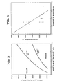
- Figure 2 and 3 illustrate that the flow rate of gas, the thickness of the outside wall and the area of the tuyere opening (i.e., the width of the annular gap of the tuyere) have the greatest effect on the critical bath temperature.
- the model was a solution of the temperature distribution in the inside wall 6, outside wall 4, and annular gas as heat flowed from the refractory brick and the liquid bath.
- Figure 2 is a plot of calculated critical bath temperatures for various wall thicknesses an argon flow rates per tuyere.
- the tuyere design had an inside diameter of outside tube 4 of 3.00 inches (76.2 mm); a central core 6 diameter of 2.88 inches (73.2 mm); an annulus gap 12 of 0.062 inch (1.6 mm).
- the critical bath temperature increases as the gas flow is increased.
- the same gas flow rate per tuyere increases the critical bath temperature.
- the gas flow rate per unit area for each curve ranges from about 171 scfm/in 2 (0.0075 m 3 /min-mm 2 ) at about 100 scf m (2.83 m 3 /min) to about 685 scfm/in 2 ( 0.03 m 3 /min-mm 2 ) at about 4 00 scfm (11.3 m 3 /min). These values are based on a cross-section tuyere area of the annulus of 0.584 square inch.
- prior art tuyeres do not operate below 150 scfm (4.25 m 3 /min) gas flow rate, or about 250 scfm/in 2 of annulus area (0.01 m 3 /min-mm 3 ).
- Figure 3 is a plot of calculated critical bath temperatures for various annular gaps and argon flowrates per tuyere.
- One tuyere had an inside diameter of outside tube 4 of 2.94 inches (74.7 mm), a central core 6 diameter of 2.88 inches (73.2 mm), an outside wall thickness of 0.156 inch (4 mm), and an annulus gap of 0.031 inch (0.8 mm).
- the other tuyere is the same as that used for Figure 2, having a 0.188-inch (4.8 mm) outside wall thickness and 0.062-inch (1.6 mm) annular gap.
- a smaller annulus operates at a higher critical bath temperature for a given flow rate per tuyere.
- a smaller annulus operates at a lower gas flow rate per tuyere.
- the gas flow rate per unit area for the 0.062-inch curve ranges from about 171 scfmjin2 (0.0075 m 3 /min-mm 2 ) at about 100 scfm (2.83 m 3 /min) to about 685 scfm/in (0.03 m 3 /min-mm 2 ) at about 400 scfm (11.3 m 3 /min).
- the gas flow rate per unit area ranges from 342 scfm/in 2 (0.015 m 3 /min-mm 2 ) to about 1368 scfm/in 2 (0.06 m 3 /min-mm 2 ) for 100 to 400 scfm, respectively.
- Figure 4 is a plot of bath temperature versus the diameter of the frozen metal on the tuyere tip for fourteen (14) heats of stainless steel refined with three tuyeres having an outside wall thickness of 0.062 inches (1.6 mm) and a gas flow of 400 scfm (11.3 m 3 /min) per tuyere.
- the diameter of the "mushroom” was estimated from photographs taken when the vessel was turned down. The diameter is plotted as a function of the bath temperature when the vessel was turned down.
- Figure 4 shows that the critical bath temperature (i.e., when the diameter of the mushroom is zero and where tuyere tip corroding and melting would occur) is in excess of 3300°F (1815°C). This data conforms well with the mathematical model of Figure 2.
- the calculated curve for 0.062 inch outside wall also suggests that the critical bath temperature should be in excess of 3300°F (1815°C) for about 400 scfm flow rate. In the actual trials, it was observed that mushrooms were formed in all cases below 3300 0 F and that the further the bath temperature was below 3300°F, the larger the diameter of the mushroom formed.
- Figures 2 and 3 also show the improved range of high to low gas flow rates per tuyere over which the tuyeres of the present invention can be used.
- the range is broadened by being able to use the tuyeres at relatively lower gas flow rates.
- Figures 2 and 3 both show improvements at lower flow rates by thinner outside walls and a reduced annular gap, respectively, which are illustrated by shifting of the curves toward higher critical bath temperatures and lower flow rates.
- the broadened range can also be expressed as a ratio of the maximum gas flow rate to minimum gas flow rate at a given critical bath temperature and for a given configuration of tuyeres.
- the usable gas flow rates range from about 200 to 400 scfm (5.7 to 11.3 m 3 /min) for the 0.188-inch wall ( Figure 2) and 0.062-inch annulus ( Figure 3), respectively.
- the ratio of maximum-to-minimum gas flow is of the order of 2:1.
- the ratio of maximum-to-minimum gas flow is of htheorder of 4:1 for gas flow rates ranging from about 100 scfm (5.7 m3/min) or less to about 400 scfm (11.3 m 3 /min).
- figure 3 illustrates the benefits of operating with a smaller annulus, making the annulus smaller without other changes and features of the present invention has its drawbacks. Decreasing the annulus alone does not decrease the gas flow per unit area and would require higher gas pressures. Though there is an improved cooling of the tuyere, the range of maximum-to-minimum flow rate is sacrificed. The benefit of providing a thinner outer wall of the tuyere improves the flow rate per unit area of the tuyere and thus widens the usable range of the tuyere.
- the tuyere structure and method of using the tuyere for blowing gas includes several other features.
- modified tuyeres can be used in existing vessels without further modifications, such as to gas pressure. If additional or increased gas pressure is available, the efficiency of the tuyere design of the present invention and method of using can result in further improvement in the tuyre life. It is also anticipated that the critical bath temperature could be further increased by using a higher melting point alloy for the tuyere materials, or a gas with a greater capacity for heat.
- a low-carbon, low-alloy steel tuyere theoretically could increase the critical bath temperature by about 18° F (8°C) over that for regular carbon steel without melting the tuyere.
- use of nitrogen or carbon dioxide, for example could be substitued in whole or part for argon and could increase the allowable bath temperature by about 40-50°F (4-10°C).
- Argon has a thermal capacity of about 418 J/kg-°C.
- a preferred method may also improve tuyere life as well as provide other advantages.
- the method includes the steps of raising the critical bath temperature by providing the tuyere with a relatively thin outer wall and a relatively small annular gap, monitoring the molten metal bath temperature and adjusting the gas flow as a function of the molten metal bath temperature to minimize the gas flow necessary to cool the tuyre tip.
- the molten metal bath of a steel alloy may range from 2500 to 3300 0 F (1371 to 1800°C).
- the operator attempt to maintain and adjust the gas flow through the tuyere as close to the curve as possible and following the curve to maintain the frozen metal layer or mushroom.
- the gas flow should be low as the bath temperature is low and increased as the bath temperature is increased. Such a method not only minimizes corroding of the tuyere and prolongs its life, but also minimizes the gas necessary for the production process. Such economic considerations provide reduced costs in producing the metal.
Landscapes
- Engineering & Computer Science (AREA)
- Chemical & Material Sciences (AREA)
- Manufacturing & Machinery (AREA)
- Materials Engineering (AREA)
- Metallurgy (AREA)
- Organic Chemistry (AREA)
- Mechanical Engineering (AREA)
- Treatment Of Steel In Its Molten State (AREA)
- Carbon Steel Or Casting Steel Manufacturing (AREA)
- Furnace Charging Or Discharging (AREA)
- Percussion Or Vibration Massage (AREA)
- Furnace Details (AREA)
- Coating With Molten Metal (AREA)
- Nozzles (AREA)
Priority Applications (1)
| Application Number | Priority Date | Filing Date | Title |
|---|---|---|---|
| AT83307952T ATE45386T1 (de) | 1983-06-14 | 1983-12-23 | Duese und verfahren zum einblasen von gas in metallschmelzen. |
Applications Claiming Priority (2)
| Application Number | Priority Date | Filing Date | Title |
|---|---|---|---|
| US504191 | 1983-06-14 | ||
| US06/504,191 US4462824A (en) | 1983-06-14 | 1983-06-14 | Annular tuyere |
Publications (3)
| Publication Number | Publication Date |
|---|---|
| EP0128987A2 true EP0128987A2 (fr) | 1984-12-27 |
| EP0128987A3 EP0128987A3 (en) | 1986-10-22 |
| EP0128987B1 EP0128987B1 (fr) | 1989-08-09 |
Family
ID=24005230
Family Applications (1)
| Application Number | Title | Priority Date | Filing Date |
|---|---|---|---|
| EP83307952A Expired EP0128987B1 (fr) | 1983-06-14 | 1983-12-23 | Tuyère et procédé pour injecter du gaz dans un bain de métal en fusion |
Country Status (8)
| Country | Link |
|---|---|
| US (1) | US4462824A (fr) |
| EP (1) | EP0128987B1 (fr) |
| AT (1) | ATE45386T1 (fr) |
| CA (1) | CA1217336A (fr) |
| DE (1) | DE3380358D1 (fr) |
| GR (1) | GR79434B (fr) |
| MX (1) | MX161196A (fr) |
| YU (1) | YU245183A (fr) |
Families Citing this family (6)
| Publication number | Priority date | Publication date | Assignee | Title |
|---|---|---|---|---|
| JPS5941387A (ja) * | 1982-08-30 | 1984-03-07 | Osaka Gas Co Ltd | ピッチの製造方法 |
| US4758269A (en) * | 1987-02-24 | 1988-07-19 | Allegheny Ludlum Corporation | Method and apparatus for introducing gas into molten metal baths |
| US4754951A (en) * | 1987-08-14 | 1988-07-05 | Union Carbide Corporation | Tuyere assembly and positioning method |
| DE3919238A1 (de) * | 1989-06-13 | 1990-12-20 | Voest Alpine Ind Anlagen | Spueleinrichtung fuer ein metallurgisches gefaess |
| DE29602813U1 (de) | 1996-02-16 | 1996-04-04 | Beck & Kaltheuner Fa | Keramischer Spülblock für metallurgische Gefäße |
| WO2008154688A1 (fr) * | 2007-06-19 | 2008-12-24 | Technological Resources Pty. Limited | Appareil pour injection de matériau solide dans une cuve |
Citations (3)
| Publication number | Priority date | Publication date | Assignee | Title |
|---|---|---|---|---|
| US2855293A (en) * | 1955-03-21 | 1958-10-07 | Air Liquide | Method and apparatus for treating molten metal with oxygen |
| US4311518A (en) * | 1979-10-31 | 1982-01-19 | Canadian Liquid Air Ltd./Air Liquide Canada Ltee | Homogenization of metal using gas |
| EP0059289A1 (fr) * | 1980-12-20 | 1982-09-08 | Kabushiki Kaisha Kobe Seiko Sho | Tuyère de soufflage |
Family Cites Families (1)
| Publication number | Priority date | Publication date | Assignee | Title |
|---|---|---|---|---|
| BE752893A (fr) * | 1969-07-08 | 1970-12-16 | Forges De La Loire St Chamond | Procede et dispositif de refroidissement d'une tuyere de convertisseur d'affinage |
-
1983
- 1983-06-14 US US06/504,191 patent/US4462824A/en not_active Expired - Lifetime
- 1983-12-15 CA CA000443357A patent/CA1217336A/fr not_active Expired
- 1983-12-15 GR GR73257A patent/GR79434B/el unknown
- 1983-12-16 YU YU02451/83A patent/YU245183A/xx unknown
- 1983-12-23 DE DE8383307952T patent/DE3380358D1/de not_active Expired
- 1983-12-23 AT AT83307952T patent/ATE45386T1/de not_active IP Right Cessation
- 1983-12-23 EP EP83307952A patent/EP0128987B1/fr not_active Expired
-
1984
- 1984-01-13 MX MX200035A patent/MX161196A/es unknown
Patent Citations (3)
| Publication number | Priority date | Publication date | Assignee | Title |
|---|---|---|---|---|
| US2855293A (en) * | 1955-03-21 | 1958-10-07 | Air Liquide | Method and apparatus for treating molten metal with oxygen |
| US4311518A (en) * | 1979-10-31 | 1982-01-19 | Canadian Liquid Air Ltd./Air Liquide Canada Ltee | Homogenization of metal using gas |
| EP0059289A1 (fr) * | 1980-12-20 | 1982-09-08 | Kabushiki Kaisha Kobe Seiko Sho | Tuyère de soufflage |
Also Published As
| Publication number | Publication date |
|---|---|
| GR79434B (fr) | 1984-10-22 |
| US4462824A (en) | 1984-07-31 |
| EP0128987B1 (fr) | 1989-08-09 |
| EP0128987A3 (en) | 1986-10-22 |
| DE3380358D1 (en) | 1989-09-14 |
| MX161196A (es) | 1990-08-15 |
| ATE45386T1 (de) | 1989-08-15 |
| CA1217336A (fr) | 1987-02-03 |
| YU245183A (en) | 1986-02-28 |
Similar Documents
| Publication | Publication Date | Title |
|---|---|---|
| US4699654A (en) | Melting furnace and method for melting metal | |
| US5270075A (en) | Ceramic welding process | |
| RU2203961C2 (ru) | Фурма для подвода сырьевого материала и способ введения твердых сырьевых материалов в металлургическую емкость | |
| US4539043A (en) | Bottom-blown gas blowing nozzle | |
| EP0356943B1 (fr) | Tuyère métallurgique résistant à l'usure | |
| EP0128987B1 (fr) | Tuyère et procédé pour injecter du gaz dans un bain de métal en fusion | |
| US4477279A (en) | Annular tuyere and method | |
| CN101784859B (zh) | 铁浴式熔融还原炉 | |
| AU733778B2 (en) | Simplified ladle refining process | |
| JP3662094B2 (ja) | アルミナ―カーボン質ガス吹込み用プラグ | |
| JPH07145414A (ja) | 金属溶解炉の溶融金属排出方法及びその排出口 | |
| JPH05331521A (ja) | 製鋼用精錬炉の出鋼口 | |
| JP2009068099A (ja) | 精錬容器のガス吹き込み羽口構造 | |
| JPH09296205A (ja) | 高炉炉壁用冷却板 | |
| SU870433A1 (ru) | Фурма доменной печи | |
| JPS60238410A (ja) | 精錬炉 | |
| JPH0625722A (ja) | 高炉の炉底底面の保護方法 | |
| JPS61195910A (ja) | 羽口構造 | |
| JP2000328114A (ja) | 高炉操業方法 | |
| JP2876955B2 (ja) | ガス吹き込み羽口を有する転炉型精錬容器の補修方法 | |
| JP3769060B2 (ja) | 溶融金属内へのガスの底吹き方法 | |
| JPH05125416A (ja) | 鉄浴式溶融還元炉用冷却構造体 | |
| JPH10273714A (ja) | 底吹き羽口 | |
| JPH0598334A (ja) | 溶融金属反応炉の炉壁構造 | |
| JPS6223052B2 (fr) |
Legal Events
| Date | Code | Title | Description |
|---|---|---|---|
| PUAI | Public reference made under article 153(3) epc to a published international application that has entered the european phase |
Free format text: ORIGINAL CODE: 0009012 |
|
| AK | Designated contracting states |
Designated state(s): AT BE DE FR GB IT LU NL SE |
|
| PUAL | Search report despatched |
Free format text: ORIGINAL CODE: 0009013 |
|
| AK | Designated contracting states |
Kind code of ref document: A3 Designated state(s): AT BE DE FR GB IT LU NL SE |
|
| 17P | Request for examination filed |
Effective date: 19870129 |
|
| 17Q | First examination report despatched |
Effective date: 19880125 |
|
| ITF | It: translation for a ep patent filed |
Owner name: FIAMMENGHI - DOMENIGHETTI |
|
| GRAA | (expected) grant |
Free format text: ORIGINAL CODE: 0009210 |
|
| AK | Designated contracting states |
Kind code of ref document: B1 Designated state(s): AT BE DE FR GB IT LU NL SE |
|
| REF | Corresponds to: |
Ref document number: 45386 Country of ref document: AT Date of ref document: 19890815 Kind code of ref document: T |
|
| REF | Corresponds to: |
Ref document number: 3380358 Country of ref document: DE Date of ref document: 19890914 |
|
| ET | Fr: translation filed | ||
| PLBE | No opposition filed within time limit |
Free format text: ORIGINAL CODE: 0009261 |
|
| STAA | Information on the status of an ep patent application or granted ep patent |
Free format text: STATUS: NO OPPOSITION FILED WITHIN TIME LIMIT |
|
| 26N | No opposition filed | ||
| PGFP | Annual fee paid to national office [announced via postgrant information from national office to epo] |
Ref country code: NL Payment date: 19901231 Year of fee payment: 8 |
|
| ITPR | It: changes in ownership of a european patent |
Owner name: CAMBIO RAGIONE SOCIALE;ALLEGHENY LUDLUM CORPORATIO |
|
| REG | Reference to a national code |
Ref country code: FR Ref legal event code: CD |
|
| PG25 | Lapsed in a contracting state [announced via postgrant information from national office to epo] |
Ref country code: NL Effective date: 19920701 |
|
| NLV4 | Nl: lapsed or anulled due to non-payment of the annual fee | ||
| ITTA | It: last paid annual fee | ||
| EPTA | Lu: last paid annual fee | ||
| EAL | Se: european patent in force in sweden |
Ref document number: 83307952.8 |
|
| PGFP | Annual fee paid to national office [announced via postgrant information from national office to epo] |
Ref country code: SE Payment date: 19951110 Year of fee payment: 13 |
|
| PGFP | Annual fee paid to national office [announced via postgrant information from national office to epo] |
Ref country code: FR Payment date: 19951114 Year of fee payment: 13 Ref country code: AT Payment date: 19951114 Year of fee payment: 13 |
|
| PGFP | Annual fee paid to national office [announced via postgrant information from national office to epo] |
Ref country code: BE Payment date: 19951123 Year of fee payment: 13 |
|
| PGFP | Annual fee paid to national office [announced via postgrant information from national office to epo] |
Ref country code: GB Payment date: 19951124 Year of fee payment: 13 |
|
| PGFP | Annual fee paid to national office [announced via postgrant information from national office to epo] |
Ref country code: DE Payment date: 19951129 Year of fee payment: 13 |
|
| PGFP | Annual fee paid to national office [announced via postgrant information from national office to epo] |
Ref country code: LU Payment date: 19951201 Year of fee payment: 13 |
|
| PG25 | Lapsed in a contracting state [announced via postgrant information from national office to epo] |
Ref country code: LU Free format text: LAPSE BECAUSE OF NON-PAYMENT OF DUE FEES Effective date: 19961223 Ref country code: GB Effective date: 19961223 Ref country code: AT Effective date: 19961223 |
|
| PG25 | Lapsed in a contracting state [announced via postgrant information from national office to epo] |
Ref country code: SE Effective date: 19961224 |
|
| PG25 | Lapsed in a contracting state [announced via postgrant information from national office to epo] |
Ref country code: BE Effective date: 19961231 |
|
| BERE | Be: lapsed |
Owner name: ALLEGHENY LUDLUM CORP. Effective date: 19961231 |
|
| GBPC | Gb: european patent ceased through non-payment of renewal fee |
Effective date: 19961223 |
|
| PG25 | Lapsed in a contracting state [announced via postgrant information from national office to epo] |
Ref country code: FR Effective date: 19970829 |
|
| PG25 | Lapsed in a contracting state [announced via postgrant information from national office to epo] |
Ref country code: DE Effective date: 19970902 |
|
| EUG | Se: european patent has lapsed |
Ref document number: 83307952.8 |
|
| REG | Reference to a national code |
Ref country code: FR Ref legal event code: ST |