EP0128722A1 - Method for supervision of injection molding by use of waveform of internal die pressure - Google Patents
Method for supervision of injection molding by use of waveform of internal die pressure Download PDFInfo
- Publication number
- EP0128722A1 EP0128722A1 EP84303756A EP84303756A EP0128722A1 EP 0128722 A1 EP0128722 A1 EP 0128722A1 EP 84303756 A EP84303756 A EP 84303756A EP 84303756 A EP84303756 A EP 84303756A EP 0128722 A1 EP0128722 A1 EP 0128722A1
- Authority
- EP
- European Patent Office
- Prior art keywords
- waveform
- die pressure
- molding
- internal die
- injection molding
- Prior art date
- Legal status (The legal status is an assumption and is not a legal conclusion. Google has not performed a legal analysis and makes no representation as to the accuracy of the status listed.)
- Granted
Links
- 238000000034 method Methods 0.000 title claims abstract description 58
- 238000001746 injection moulding Methods 0.000 title claims abstract description 31
- 238000000465 moulding Methods 0.000 claims abstract description 44
- 239000011347 resin Substances 0.000 claims abstract description 29
- 229920005989 resin Polymers 0.000 claims abstract description 29
- 238000005070 sampling Methods 0.000 claims description 9
- 230000005856 abnormality Effects 0.000 abstract description 20
- 238000012544 monitoring process Methods 0.000 abstract description 3
- 238000005429 filling process Methods 0.000 description 11
- 230000000052 comparative effect Effects 0.000 description 8
- 230000002159 abnormal effect Effects 0.000 description 6
- 238000010586 diagram Methods 0.000 description 5
- 230000006870 function Effects 0.000 description 3
- 230000007306 turnover Effects 0.000 description 3
- 238000012937 correction Methods 0.000 description 2
- 238000002347 injection Methods 0.000 description 2
- 239000007924 injection Substances 0.000 description 2
- 229920003023 plastic Polymers 0.000 description 2
- 239000004033 plastic Substances 0.000 description 2
- 230000010485 coping Effects 0.000 description 1
- 230000001186 cumulative effect Effects 0.000 description 1
- 238000011161 development Methods 0.000 description 1
- 230000001788 irregular Effects 0.000 description 1
- 238000004519 manufacturing process Methods 0.000 description 1
- 238000012545 processing Methods 0.000 description 1
Images


Classifications
-
- B—PERFORMING OPERATIONS; TRANSPORTING
- B29—WORKING OF PLASTICS; WORKING OF SUBSTANCES IN A PLASTIC STATE IN GENERAL
- B29C—SHAPING OR JOINING OF PLASTICS; SHAPING OF MATERIAL IN A PLASTIC STATE, NOT OTHERWISE PROVIDED FOR; AFTER-TREATMENT OF THE SHAPED PRODUCTS, e.g. REPAIRING
- B29C45/00—Injection moulding, i.e. forcing the required volume of moulding material through a nozzle into a closed mould; Apparatus therefor
- B29C45/17—Component parts, details or accessories; Auxiliary operations
- B29C45/76—Measuring, controlling or regulating
- B29C45/77—Measuring, controlling or regulating of velocity or pressure of moulding material
-
- G—PHYSICS
- G05—CONTROLLING; REGULATING
- G05B—CONTROL OR REGULATING SYSTEMS IN GENERAL; FUNCTIONAL ELEMENTS OF SUCH SYSTEMS; MONITORING OR TESTING ARRANGEMENTS FOR SUCH SYSTEMS OR ELEMENTS
- G05B19/00—Programme-control systems
- G05B19/02—Programme-control systems electric
- G05B19/04—Programme control other than numerical control, i.e. in sequence controllers or logic controllers
- G05B19/048—Monitoring; Safety
Definitions
- This invention relates to a method for the supervision of the quality of molded articles produced by injection molding and particularly to a method for the supervision of injection molding from the outset of the filling of molten resin into a mold to the completion of the molding on the basis of waveform of the inner die pressure in a resin passageway in the mold.
- the prior art apparatus utilizes the resin pressure in a mold cavity as one of variables in the molding process.
- the idea of determining reference, allowable and critical values of the resin pressure at one molding shot is not disclosed at all.
- the term "resin pressure” used therein is generally termed as "peak pressure”, but does not signify internal die pressure described later.
- the aforementioned apparatus does not serve a function of comparing each molding shot with the optimum reference shot which is experimentally determined in advance.
- the inner die pressure represents the conditions of the molten resin from the outset of the filling process to the termination of the dwelling process and is detected by means of a sensor disposed in a resin passageway for introducing molten into the mold.
- the internal die pressure in the resin passageway should be distinguished from the resin pressure considered as peak pressure which is detected by means of a sensor disposed in a cavity of the mold as disclosed in Japanese Utility Mode Publication Sho.
- the waveform of the internal die pressure shows the variation in condition of one molding shot, under which a molded article is produced and is referred to as the result of each molding condition. Accordingly, the supervision of the quality of molded articles can be carried out by use of the aforementioned waveform of the internal die pressure.
- An object of this invention is to provide a method for the supervision of an injection molding process, which is capable of finding out the process causing abnormality at each shot of injection molding and promptly coping with the abnormality, thereby to resume its optimum molding condition and enjoy high degree of reproducibility.
- a method for the supervision of injection molding by use of the waveform of internal die pressure which comprises displaying reference waveform of the internal die pressure together with monitored wavefore of actual internal die pressure detected in a mold at each shot of the injection molding and comparing the detected value of the monitored waveform with the allowable value of the reference waveform.
- the reference waveform of internal die pressure is previously determined by continuously monitoring the internal die pressure in a resin passageway for introducing molten resin into a mold and choosing the waveform of the internal die pressure under which molded articles of good quality are produced.
- the waveform obtained by monitoring the internal die pressure at each shot of the injection molding is compared with the predetermined reference waveform described above to find whether the detected value based on the monitored internal die pressure exceeds the allowable value based on the reference waveform, and when the detected value exceeds the allowable value, the molding process causing abnormality is revealed by use of a suitable means for issuing a warning.
- the data thus detected is arbitrarily outputted for a record through the medium of a CRT or the like. Futhermore, the data is, otherwise, fed back to a driving system for the molding machine, consequently to enable stable production of molded articles of good quality to be maintained for a long time.
- Figure 1 is a block circuit diagram illustrating one preferred embodiment of the method for the supervision by use of the waveform of internal die pressure according to this invention.
- 1 denotes a pressure sensor disposed in a resin passageway for introducing molten resin inside a mold d, and 2 a pressure detector for detecting as a signal the resin pressure (internal die pressure) exerted on the pressure sensor 1.
- the molten resin is injected into the mold d through the nozzle of an injection molding machine M, and when the leading surface of the molten resin flowing into the mold reaches the resin passageway portion in the mold, the pressure of the molten resin is detected as internal die pressure by the pressure sensor 1. Accordingly, the internal die pressure of the molten resin in the passageway is expressed as a continuous waveform by the pressure varying with time from the filling process of the molten resin to the completion of the molding.
- 4 a reference waveform setting unit memorizing reference waveform of internal die pressure under which molded articles of good quality are produced.
- the reference waveform is predetermined on the basis of the electric signals fed from the converter 3.
- a monitored pressure an input unit to which actual internal die pressure monitored by use of the detector 2 at each shot of the injection molding is given as a waveform signal.
- the display unit 7 may be composed of a cathode-ray tube (CRT), for example. On this display unit 7 are displayed the results of the computating operation which is outputted from the comparative processor 6.
- Denoted by 8 is an output unit for delivering as output signals the results of the computating operation from the processor 6.
- the reference internal die pressure thus determined is memorized as an optimum reference waveform of internal die pressure in the reference waveform setting unit 4.
- the aforementioned reference waveform is subjected to sampling at interval of a fixed time to produce corresponding digital signals. Namely, the reference waveform is divided into n-signals as the time proceeds.
- the sampled signal representing pressure value P i is memorized at the time n i as reference valus, and that of the subsequent pressure values P i+1 is also memorized at the time n i+1 as the subsequent reference value.
- the sampled signals are memorized in order as the reference pressure values in the reference waveform setting unit 4.
- the allowable value E at each sampling time is set in a memory 11 of the comparative processor 6.
- the allowable values E are determined by taking the molding condition for judging the abnormality of the molded article into consideration and displyed on the CRT as a continuous waveform which is irregular in width and contains the aforementioned reference waveform, as defined by the chain lines in Figure 5.
- the aforementioned reference waveform can be selectively varied by each process in one injection molding from the point of view of the requirement for the accuracy of the desired products. That is to say, as illustrated in Figure 2, the waveform at one molding shot can be considered as two parts, one being a filling process I in which the internal die pressure is rapidly varied and the other being a dwelling process in which the internal die pressure is gradually varied, so that they can individually be observed.
- a criterional value for judgement of the abnormality in the injection wolding is also memorized.
- the aforementioned input unit 5 receives the monitored values p i which are serially obtained by subjecting the internal die pressure detected at each shot to sampling operation in the same way as the reference waveform is memorized in the reference waveform setting unit.
- the reference waveform is inputted to the reference waveform setting unit 4. If the reference waveform is predetermined, it may be inputted from an external memory 4' to the unit 4. Simultaneously, the reference waveform is displayed on the display unit 7.
- the internal die pressure varying with time is successively detected and given as monitored waveform to the input unit 5.
- the monitored waveform is displyed on the display unit 7.
- the reference value i and the detected value p i are fed to the comparative processor 6. Assume that the time required for one molding shot is divided by n to make signal train defined by the time i.
- thus obtained is compared with the allowable value E so as to examine deviation value
- is smaller than the value E, the molding shot under observation is regarded as being normal.
- the detected waveform is subjected to discriminating operation in discriminators 12a and 12b thereby to find which process of filling or dwelling causes abnormality.
- the count of the value exceeding the allowable value is measured every sampling time renewed by adding 1 to the foregoing sampling value S I .
- the successive sampling (i+1) is performed.
- the one molding shot is finished by repeating the aforementioned procedures n-times, and thereafter, the judgement for evaluating the result of the molding shot is formed by comparing the deviation value described above with criterional values a I and a II which are set in a criterion setting unit 13 for the respective processes.
- an OR gate circuit 14 delivers a command signal to the output unit 8.
- the monitored waveform of one molding shot which is obtained by the procedure described above is superposed upon the reference waveform on the screen of the display unit 7, thereby enabling the abnormal process to be recognized promptly.
- comparison of the monitored waveform (dotted line) and the reference waveform (solid line) indicates that abnormalities exist at points a and b at which the monitored waveform is deviated from the allowable range (defined by chain lines).
- T represents a turnover point between the processes I and II.
- the injection molding is continuously carried out.
- abnormality occurs, it is dealt with in accordance with various command signals produced out of the output unit 8.
- an alarm or warning may be issued while the abnormal point (points a and b, for example) is indicated by a carsor indicator on the screen of the display unit.
- an operator can confirm the existence of the abnormality in the molding on the display unit with his eye.
- cumulative value of the abnormalities caused in the molding shots repeatedly carried out is displayed in a digital form, so that degree of the abnormality can be confirmed numerically. Otherwise, the output signal as a feed-back signal may be forwarded to an automatic correction device.
- weight value can be included in the judging factors for abnormality in the injection molding .
- the molding process into a filling process and a dwelling process, supervision desirable for the optimum molding condition can be accomplished with accuracy.
- the period of the filling process (O-T) is instantaneous in comparison with that of the dwelling process (T-n). Accordingly, the turnover point T is shifted to extend the period of the filling process as illustrated, with the result that the sampling number in the filling process (O-T) is made larger than that in the dwelling process per unit time. Consequently, even a little change which is brought about in the filling process can precisely be observed on the waveform displayed on the screen of the display unit 7.
- the molding shot is not restricted to be divided into two processes.
- the two processes may be subdivided into four processes, for example, so that the processes can be provided with the respective weight values according to the required accuracy of a molded article.
- the method for the supervision in injection molding permits the quality of molded articles to be supervised with accuracy on the basis of the reference waveform representing the optimum internal die pressure and enjoys high degree of reproducibility. Further, suitable condition for dealing with abnormality caused at each shot of injection molding can promptly be determined in a short time in accordance with the predetermined waveform of the optimum internal die pressure. Besides, an operator can correctly find out what process is abnormal by observing the monitored waveform of the detected internal die pressure in comparison with the predetermined reference waveform displayed on the display unit, thereby enabling each process of the molding injection to be manually handled.
Landscapes
- Engineering & Computer Science (AREA)
- Physics & Mathematics (AREA)
- General Physics & Mathematics (AREA)
- Automation & Control Theory (AREA)
- Manufacturing & Machinery (AREA)
- Mechanical Engineering (AREA)
- Injection Moulding Of Plastics Or The Like (AREA)
- Force Measurement Appropriate To Specific Purposes (AREA)
Abstract
Description
- This invention relates to a method for the supervision of the quality of molded articles produced by injection molding and particularly to a method for the supervision of injection molding from the outset of the filling of molten resin into a mold to the completion of the molding on the basis of waveform of the inner die pressure in a resin passageway in the mold.
- As one conventional supervising method of this type, there has been proposed an apparatus for the correction of molding data obtained during injection molding disclosed in Japanese Patent Application Public Disclosure Sho. 57(1982)-212041. Although the prior art apparatus can observe an occurrence of abnormality every shot of injection molding and a variation in the condition of the respective shots of injection molding, it nevertheless cannot find out what process is abnormal at one shot of injection molding and what may be the cause. With the prior art apparatus, the cause of abnormality in molding can therefore be investigated as a result of compiling statistics of the entire molding condition of several molding shots carried out for fixed times.
- Further, the prior art apparatus, as claimed in the disclosure, utilizes the resin pressure in a mold cavity as one of variables in the molding process. However, the idea of determining reference, allowable and critical values of the resin pressure at one molding shot is not disclosed at all. Besides, the term "resin pressure" used therein is generally termed as "peak pressure", but does not signify internal die pressure described later.
- Furthermore, there has been proposed in the disclosure a method of displaying on a cathode-ray tube device the deviation value of variables obtained over the entire molding lots. However, the injection molding as continuing process from the outset of the filling of molten resin to the completion of the molding cannot be indicated every shot of injection molding.
- Still more, the aforementioned apparatus does not serve a function of comparing each molding shot with the optimum reference shot which is experimentally determined in advance.
- Now, in keeping with the development of enginnering plastics of today, injection molding is naturally required to be accomplished with reproduction on the order of microns and to promptly resume the optimum molding condition thereof when an accident occurs.
- In order to meet the former requirement, it is necessary to judge abnormality at each shot of injection molding and further find out what process is abnormal in the injection molding. This is because the quality of molded articles depends practically on various factors over several molding processes from the outset of the filling process for injecting molten resin into the mold to the termination of the dwelling process, and therefore, supervision of examining an molded article to see whether it is good or not cannot promptly be accomplished with accuracy unless the process in which the abnormality is caused is found out. Accordingly, the standpoint of supervision is the primary requisite to examine the quality of the molded articles.
- One of the present inventors of this invention previously accomplished a method of enabling resin pressure in a mold to be saized as a continuous waveform of internal die pressure of molten resin filled in the mold, which is obtained on the basis of functions of properties of plastics as disclosed in Japanese Patent Application Public Disclosure Sho. 52(1887)-14658. The inner die pressure represents the conditions of the molten resin from the outset of the filling process to the termination of the dwelling process and is detected by means of a sensor disposed in a resin passageway for introducing molten into the mold. In this sense, the internal die pressure in the resin passageway should be distinguished from the resin pressure considered as peak pressure which is detected by means of a sensor disposed in a cavity of the mold as disclosed in Japanese Utility Mode Publication Sho. 39(1964)-18976 and it is expressed as pressure waveform in the form of an analogue. That is to say, the waveform of the internal die pressure shows the variation in condition of one molding shot, under which a molded article is produced and is referred to as the result of each molding condition. Accordingly, the supervision of the quality of molded articles can be carried out by use of the aforementioned waveform of the internal die pressure.
- In order to comply with the latter of the requirements so far described, it is desired to compare each shot of injection molding with the reference shot under observation, thereby promptly detecting what process differs from that under the optimum condition. Consequently, the cause of the deviation in the molding process can be estimated from the abnormal portion thus recognized.
- An object of this invention is to provide a method for the supervision of an injection molding process, which is capable of finding out the process causing abnormality at each shot of injection molding and promptly coping with the abnormality, thereby to resume its optimum molding condition and enjoy high degree of reproducibility.
- To accomplish the object described above according to the present invention, there is provided a method for the supervision of injection molding by use of the waveform of internal die pressure, which comprises displaying reference waveform of the internal die pressure together with monitored wavefore of actual internal die pressure detected in a mold at each shot of the injection molding and comparing the detected value of the monitored waveform with the allowable value of the reference waveform.
- The reference waveform of internal die pressure is previously determined by continuously monitoring the internal die pressure in a resin passageway for introducing molten resin into a mold and choosing the waveform of the internal die pressure under which molded articles of good quality are produced.
- The waveform obtained by monitoring the internal die pressure at each shot of the injection molding is compared with the predetermined reference waveform described above to find whether the detected value based on the monitored internal die pressure exceeds the allowable value based on the reference waveform, and when the detected value exceeds the allowable value, the molding process causing abnormality is revealed by use of a suitable means for issuing a warning. The data thus detected is arbitrarily outputted for a record through the medium of a CRT or the like. Futhermore, the data is, otherwise, fed back to a driving system for the molding machine, consequently to enable stable production of molded articles of good quality to be maintained for a long time.
- The other objects and characteristic features of the present invention will become apparent from detailed description to be given hereinafter with reference to the accompanying drawings.
- Figure 1 is a block circuit diagram illustrating one preferred embodiment of the method for the supervision by use of the waveform of internal die pressure according to this invention.
-
- Figure 2 is an explanatory diagram illustrating the waveform representing time-varying internal die pressure.
- Figure 3 is an explanatory block diagram illustrating a fundamental function of this invention.
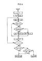
- Figure 4 is a flow chart illustrating the procedure of the processing according to the method of this invention for the supervision of injection molding.
- Figure 5 is a schematic diagram showing the monitored waveform superposed on the reference waveform.
- In the drawings, 1 denotes a pressure sensor disposed in a resin passageway for introducing molten resin inside a mold d, and 2 a pressure detector for detecting as a signal the resin pressure (internal die pressure) exerted on the
pressure sensor 1. The molten resin is injected into the mold d through the nozzle of an injection molding machine M, and when the leading surface of the molten resin flowing into the mold reaches the resin passageway portion in the mold, the pressure of the molten resin is detected as internal die pressure by thepressure sensor 1. Accordingly, the internal die pressure of the molten resin in the passageway is expressed as a continuous waveform by the pressure varying with time from the filling process of the molten resin to the completion of the molding. 3 denotes a converter for converting the pressure signal outputted from thepressure detector 2 to an electric signal, and 4 a reference waveform setting unit memorizing reference waveform of internal die pressure under which molded articles of good quality are produced. The reference waveform is predetermined on the basis of the electric signals fed from theconverter 3. By 5 is denoted a monitored pressure an input unit to which actual internal die pressure monitored by use of thedetector 2 at each shot of the injection molding is given as a waveform signal. 6 denotes a comparative processor for comparing the predetermined reference waveform set in the referencewaveform setting unit 4 with the monitored waveform given to theinput unit 5, and 7 a display unit for displaying the monitored waveform fed from theinput unit 5 together with the reference waveform outputted from the referencewaveform setting unit 4 and arbitrarily displaying the result of computating the monitored and reference waveforms by a comparative operation in theprocessor 6. Thedisplay unit 7 may be composed of a cathode-ray tube (CRT), for example. On thisdisplay unit 7 are displayed the results of the computating operation which is outputted from thecomparative processor 6. Denoted by 8 is an output unit for delivering as output signals the results of the computating operation from theprocessor 6. - To be specific, experimental injection moldings are previously carried out several times considering the molding condition inclusive of the kind of the resin to be handled, the shape of the mold to be used and a desired accuracy of molded article to be produced, thereby finding internal die pressure under which molded articles of good quality can be produced. The reference internal die pressure thus determined is memorized as an optimum reference waveform of internal die pressure in the reference
waveform setting unit 4. The aforementioned reference waveform is subjected to sampling at interval of a fixed time to produce corresponding digital signals. Namely, the reference waveform is divided into n-signals as the time proceeds. For example, the sampled signal representing pressure value Pi is memorized at the time ni as reference valus, and that of the subsequent pressure values Pi+1 is also memorized at the time ni+1 as the subsequent reference value. Likewise, the sampled signals are memorized in order as the reference pressure values in the referencewaveform setting unit 4. The allowable value E at each sampling time is set in amemory 11 of thecomparative processor 6. The allowable values E are determined by taking the molding condition for judging the abnormality of the molded article into consideration and displyed on the CRT as a continuous waveform which is irregular in width and contains the aforementioned reference waveform, as defined by the chain lines in Figure 5. - To be more specific, the aforementioned reference waveform can be selectively varied by each process in one injection molding from the point of view of the requirement for the accuracy of the desired products. That is to say, as illustrated in Figure 2, the waveform at one molding shot can be considered as two parts, one being a filling process I in which the internal die pressure is rapidly varied and the other being a dwelling process in which the internal die pressure is gradually varied, so that they can individually be observed.
- Further, in the reference
waveform setting unit 4, a criterional value for judgement of the abnormality in the injection wolding is also memorized. - The
aforementioned input unit 5 receives the monitored values pi which are serially obtained by subjecting the internal die pressure detected at each shot to sampling operation in the same way as the reference waveform is memorized in the reference waveform setting unit. - Now, the supervision by use of the aforementioned device will be described hereinafter.
- At the beginning, the reference waveform is inputted to the reference
waveform setting unit 4. If the reference waveform is predetermined, it may be inputted from an external memory 4' to theunit 4. Simultaneously, the reference waveform is displayed on thedisplay unit 7. - When the molding shot starts while being monitored in the manner described above, the internal die pressure varying with time is successively detected and given as monitored waveform to the
input unit 5. At the same time, the monitored waveform is displyed on thedisplay unit 7. Simultaneously, the reference value i and the detected value pi are fed to thecomparative processor 6. Assume that the time required for one molding shot is divided by n to make signal train defined by the time i. First, the value of the time i-1 clears away from the comparative processor 6 (SI=SII=0), and then the reference value Pi fed from the referencewaveform setting unit 4 and the detected value pi fed from theinput unit 5 are given to thecomparative processor 5, thereby obtaining deviation value (|εi|=|pi-pi|) The deviation value |εi| thus obtained is compared with the allowable value E so as to examine deviation value |εi| to find whether it is larger than the allowable value E (|εi|>E) When the deviation value |εi| is smaller than the value E, the molding shot under observation is regarded as being normal. When the value |εi| is larger, the detected waveform is subjected to discriminating operation indiscriminators criterion setting unit 13 for the respective processes. When abnormality is recognized in either process, anOR gate circuit 14 delivers a command signal to theoutput unit 8. - The monitored waveform of one molding shot which is obtained by the procedure described above is superposed upon the reference waveform on the screen of the
display unit 7, thereby enabling the abnormal process to be recognized promptly. As illustrated in Figure 5 as one example, comparison of the monitored waveform (dotted line) and the reference waveform (solid line) indicates that abnormalities exist at points a and b at which the monitored waveform is deviated from the allowable range (defined by chain lines). In this diagram, T represents a turnover point between the processes I and II. - In case of normal molding condition, the injection molding is continuously carried out. However, when abnormality occurs, it is dealt with in accordance with various command signals produced out of the
output unit 8. To be concrete, in this case an alarm or warning may be issued while the abnormal point (points a and b, for example) is indicated by a carsor indicator on the screen of the display unit. Thus, an operator can confirm the existence of the abnormality in the molding on the display unit with his eye. As occasion demands, cumulative value of the abnormalities caused in the molding shots repeatedly carried out is displayed in a digital form, so that degree of the abnormality can be confirmed numerically. Otherwise, the output signal as a feed-back signal may be forwarded to an automatic correction device. - According to the embodiment described above, since the criterional values for judging abnormality in the injection molding are selectively set for the respective processes I and II, weight value can be included in the judging factors for abnormality in the injection molding . under observation in conformity to the degree of importance in the molding processes. Specifically, by dividing the molding process into a filling process and a dwelling process, supervision desirable for the optimum molding condition can be accomplished with accuracy.
- Another embodiment according to this invention will be described hereinafter with reference to Figure 6, in which the turnover point T between the filling process I and the dwelling process II can freely be shifted on the molding waveform.
- The period of the filling process (O-T) is instantaneous in comparison with that of the dwelling process (T-n). Accordingly, the turnover point T is shifted to extend the period of the filling process as illustrated, with the result that the sampling number in the filling process (O-T) is made larger than that in the dwelling process per unit time. Consequently, even a little change which is brought about in the filling process can precisely be observed on the waveform displayed on the screen of the
display unit 7. - Although the method for the supervision in which one molding shot is composed of a filling process I and a dwelling process II is so far described, the molding shot is not restricted to be divided into two processes. The two processes may be subdivided into four processes, for example, so that the processes can be provided with the respective weight values according to the required accuracy of a molded article. Likewise, it is not indispensable for this invention to divide one molding shot under observation into the aforementioned two processes. Namely, the entire molding process may be observed collectively in the case where a high accuracy is not required for a molded article to be produced.
- Otherwise, either of the processes I and II may selectively be observed as occasion demands.
- As is clear from the description given above, the method for the supervision in injection molding according to this invention permits the quality of molded articles to be supervised with accuracy on the basis of the reference waveform representing the optimum internal die pressure and enjoys high degree of reproducibility. Further, suitable condition for dealing with abnormality caused at each shot of injection molding can promptly be determined in a short time in accordance with the predetermined waveform of the optimum internal die pressure. Besides, an operator can correctly find out what process is abnormal by observing the monitored waveform of the detected internal die pressure in comparison with the predetermined reference waveform displayed on the display unit, thereby enabling each process of the molding injection to be manually handled.
Claims (2)
Applications Claiming Priority (2)
| Application Number | Priority Date | Filing Date | Title |
|---|---|---|---|
| JP58099243A JPS59224323A (en) | 1983-06-03 | 1983-06-03 | Monitoring method by in-mold pressure wave form |
| JP99243/83 | 1983-06-03 |
Publications (3)
| Publication Number | Publication Date |
|---|---|
| EP0128722A1 true EP0128722A1 (en) | 1984-12-19 |
| EP0128722B1 EP0128722B1 (en) | 1989-03-15 |
| EP0128722B2 EP0128722B2 (en) | 1997-06-11 |
Family
ID=14242251
Family Applications (1)
| Application Number | Title | Priority Date | Filing Date |
|---|---|---|---|
| EP84303756A Expired - Lifetime EP0128722B2 (en) | 1983-06-03 | 1984-06-04 | Method for supervision of injection molding by use of waveform of internal die pressure |
Country Status (4)
| Country | Link |
|---|---|
| US (1) | US4889667A (en) |
| EP (1) | EP0128722B2 (en) |
| JP (1) | JPS59224323A (en) |
| DE (1) | DE3477152D1 (en) |
Cited By (9)
| Publication number | Priority date | Publication date | Assignee | Title |
|---|---|---|---|---|
| EP0216939A1 (en) * | 1985-03-28 | 1987-04-08 | Fanuc Ltd. | Injection molding machine with graphics display of metering conditions |
| EP0279081A1 (en) * | 1987-02-16 | 1988-08-24 | Consiglio Nazionale Delle Ricerche | An apparatus and method for controlling the cross-linking of elastomers in a mould |
| EP0299085A1 (en) * | 1987-01-30 | 1989-01-18 | Sumitomo Heavy Industries, Ltd | Method and apparatus for setting injection pressure of injection molding machine |
| EP0418398A1 (en) * | 1989-03-28 | 1991-03-27 | Fanuc Ltd. | Apparatus for discriminating acceptable products from rejectable products for injection molding machines |
| US5015426A (en) * | 1989-05-18 | 1991-05-14 | Galic Maus Ventures | Precision single cavity and multicavity plastic injection molding via an adaptive mold process |
| EP0457230A2 (en) * | 1990-05-18 | 1991-11-21 | Allen-Bradley Company, Inc. | Selectable control function injection molding controller |
| US5068065A (en) * | 1990-07-31 | 1991-11-26 | Galic Maus Ventures | Faster cycling sprue method and apparatus for injection molding plastic optical disks |
| EP0531532A1 (en) * | 1991-01-14 | 1993-03-17 | Fanuc Ltd. | Method of setting waveform of pressure in injection pressure control and injection molding machine |
| EP0744267A2 (en) * | 1995-05-24 | 1996-11-27 | Maschinenfabrik Müller-Weingarten Ag | Method for monitoring and/or controlling an injection moulding machine |
Families Citing this family (33)
| Publication number | Priority date | Publication date | Assignee | Title |
|---|---|---|---|---|
| JPS61249730A (en) * | 1985-04-30 | 1986-11-06 | Fanuc Ltd | Injection molding machine displaying injection terms graphically |
| JPS6232019A (en) * | 1985-08-05 | 1987-02-12 | Toyo Kikai Kinzoku Kk | Injection molding machine |
| JPS62187009A (en) * | 1986-02-14 | 1987-08-15 | Toyo Kikai Kinzoku Kk | Molding condition monitor for injection molding machine |
| JPS63130326A (en) * | 1986-11-20 | 1988-06-02 | Nissei Plastics Ind Co | Molding condition setting equipment for injection molding machine |
| JPH0694152B2 (en) * | 1988-03-28 | 1994-11-24 | 宇部興産株式会社 | Monitor data storage method |
| JPH0684032B2 (en) * | 1988-04-20 | 1994-10-26 | 東芝機械株式会社 | Control method in injection compression molding |
| JP2586943B2 (en) * | 1988-05-17 | 1997-03-05 | ファナック株式会社 | Inspection machine for injection molding machine |
| JPH01295816A (en) * | 1988-05-24 | 1989-11-29 | Shin Etsu Chem Co Ltd | Injection molding apparatus |
| JPH085107B2 (en) * | 1988-08-04 | 1996-01-24 | ファナック株式会社 | Positioning method in electric injection molding machine |
| DE68919462T2 (en) * | 1988-09-30 | 1995-07-20 | Ube Industries | Method and device for regulating a die casting process by controlling the movement of the pressure piston. |
| JPH02128821A (en) * | 1988-11-09 | 1990-05-17 | Toshiba Mach Co Ltd | Method and apparatus for setting optimum molding condition of injection molding machine |
| US5611975A (en) * | 1989-11-02 | 1997-03-18 | Fanuc, Ltd. | Molding condition setting method for an injection molding machine |
| JP2628384B2 (en) * | 1989-11-14 | 1997-07-09 | ファナック株式会社 | Product quality judgment method for injection molding machines |
| JP2828782B2 (en) * | 1990-12-11 | 1998-11-25 | 住友重機械工業株式会社 | Pattern generation support device for injection molding machines |
| JP2649996B2 (en) * | 1991-04-09 | 1997-09-03 | ファナック株式会社 | Injection pressure monitoring method |
| JPH0753405B2 (en) * | 1991-11-28 | 1995-06-07 | 花王株式会社 | METHOD AND DEVICE FOR CONTROLLING VARIATION OF RESIN FLOW PHYSICAL PROPERTY IN INJECTION MOLDING MACHINE |
| JP2838647B2 (en) * | 1994-05-16 | 1998-12-16 | 住友重機械工業株式会社 | Method and apparatus for setting ejector return limit completion position of ejector mechanism in injection molding machine |
| US5979336A (en) * | 1997-01-10 | 1999-11-09 | Whitney Design, Inc. | Door mounted ironing board |
| JP3583047B2 (en) * | 2000-03-07 | 2004-10-27 | 日精樹脂工業株式会社 | Drift detection method of control device for injection molding machine |
| JP2001277319A (en) * | 2000-04-03 | 2001-10-09 | Fanuc Ltd | Method for judging molding characteristics and injection molding machine |
| JP4635309B2 (en) * | 2000-09-12 | 2011-02-23 | 双葉電子工業株式会社 | Defective product detection method and apparatus, and molding apparatus. |
| DE502006007545D1 (en) * | 2005-04-28 | 2010-09-09 | Netstal Ag Maschf Giesserei | METHOD AND DEVICE FOR AUTOMATIC MONITORING OF REPETITIVE RUNNING OF AN INJECTION MOLDING MACHINE |
| ES2331720A1 (en) * | 2009-06-24 | 2010-01-13 | Universidad De La Rioja | Method for predicting the final quality of elastomer sections |
| US8980146B2 (en) | 2013-08-01 | 2015-03-17 | Imflux, Inc. | Injection molding machines and methods for accounting for changes in material properties during injection molding runs |
| AU2014296147A1 (en) | 2013-08-01 | 2016-02-18 | iMFLUX Inc. | Injection molding machines and methods for accounting for changes in material properties during injection molding runs |
| EP3027382B1 (en) | 2013-08-01 | 2019-04-24 | Imflux Inc. | Injection molding machines and methods for accounting for changes in material properties during injection molding runs |
| JP6494113B2 (en) * | 2016-07-26 | 2019-04-03 | 双葉電子工業株式会社 | Measuring device, measuring method, program |
| JP6532845B2 (en) * | 2016-07-26 | 2019-06-19 | 双葉電子工業株式会社 | Measuring device, measuring method, program |
| US10894349B2 (en) * | 2016-11-18 | 2021-01-19 | iMFLUX Inc. | Method for controlling valve gates using one or more strain gauges |
| US10836088B2 (en) | 2017-04-25 | 2020-11-17 | Kistler Holding, Ag | Method for reproducing injection molded parts of quality and injection molding unit for performing the method |
| JP6687574B2 (en) * | 2017-09-26 | 2020-04-22 | 双葉電子工業株式会社 | Arithmetic processing device, arithmetic method of arithmetic processing device, and program |
| JP6772119B2 (en) * | 2017-09-26 | 2020-10-21 | 双葉電子工業株式会社 | Arithmetic processing unit, arithmetic processing unit arithmetic method and program |
| FR3104482B1 (en) * | 2019-12-16 | 2023-04-28 | Schneider Electric Ind Sas | Process for molding a part by plastic injection and instrumented mold intended to implement such a process |
Citations (1)
| Publication number | Priority date | Publication date | Assignee | Title |
|---|---|---|---|---|
| JPS5214658A (en) * | 1975-05-29 | 1977-02-03 | Hisashi Kojima | Method and device for controlling internal pressure in injection molding machine mold |
Family Cites Families (10)
| Publication number | Priority date | Publication date | Assignee | Title |
|---|---|---|---|---|
| JPS5022505Y2 (en) * | 1971-03-31 | 1975-07-08 | ||
| JPS5611919B2 (en) * | 1972-09-27 | 1981-03-17 | ||
| US3840312A (en) * | 1973-04-11 | 1974-10-08 | Control Process Inc | Dynamic pressure control system |
| US4060362A (en) * | 1975-05-12 | 1977-11-29 | International Business Machines Corporation | Injection molding same cycle control |
| DE2615445C3 (en) * | 1976-04-09 | 1981-09-10 | Westfälische Metall Industrie KG Hueck & Co, 4780 Lippstadt | Method for controlling an injection molding machine with observation of the pressure curve in the injection mold |
| US4359435A (en) * | 1978-04-19 | 1982-11-16 | Yamato Kogure | Method for manufacturing plastic products |
| JPS5611919U (en) * | 1979-07-04 | 1981-01-31 | ||
| JPS5661319A (en) * | 1979-10-24 | 1981-05-26 | Dainippon Ink & Chem Inc | Production of unsaturated ketone |
| JPS57212041A (en) * | 1981-06-24 | 1982-12-27 | Toshiba Mach Co Ltd | Molding data collector for injection molding machine |
| US4399098A (en) * | 1981-09-21 | 1983-08-16 | Dearborn Chemical Company | Prevention of corrosion in aqueous solutions |
-
1983
- 1983-06-03 JP JP58099243A patent/JPS59224323A/en active Granted
-
1984
- 1984-06-04 DE DE8484303756T patent/DE3477152D1/en not_active Expired
- 1984-06-04 EP EP84303756A patent/EP0128722B2/en not_active Expired - Lifetime
-
1987
- 1987-05-21 US US07/053,567 patent/US4889667A/en not_active Expired - Fee Related
Patent Citations (1)
| Publication number | Priority date | Publication date | Assignee | Title |
|---|---|---|---|---|
| JPS5214658A (en) * | 1975-05-29 | 1977-02-03 | Hisashi Kojima | Method and device for controlling internal pressure in injection molding machine mold |
Non-Patent Citations (2)
| Title |
|---|
| DIEHL, O.: "Bildschirmsteuerung SMP-E 352", SIEMENS COMPONENTS, vol. 19, no. 2, March 1981 (1981-03-01), BERLIN-MÜNCHEN, pages 46 - 49 * |
| KESSELHUT, H.: "Fortschrittliches Automatisieren von Kunststoffverarbeitungsmaschinen mit dem Microcomputer S5-210A", SIEMENS-ENERGIETECHNIK, vol. 4, no. 5, September 1982 (1982-09-01), BERLIN-MÜNCHEN, pages 226 - 229 * |
Cited By (16)
| Publication number | Priority date | Publication date | Assignee | Title |
|---|---|---|---|---|
| EP0216939A4 (en) * | 1985-03-28 | 1988-07-21 | Fanuc Ltd | Injection molding machine with graphics display of metering conditions. |
| EP0216939A1 (en) * | 1985-03-28 | 1987-04-08 | Fanuc Ltd. | Injection molding machine with graphics display of metering conditions |
| EP0299085A1 (en) * | 1987-01-30 | 1989-01-18 | Sumitomo Heavy Industries, Ltd | Method and apparatus for setting injection pressure of injection molding machine |
| EP0299085A4 (en) * | 1987-01-30 | 1990-09-05 | Sumitomo Heavy Industries, Ltd | Method and apparatus for setting injection pressure of injection molding machine |
| EP0279081A1 (en) * | 1987-02-16 | 1988-08-24 | Consiglio Nazionale Delle Ricerche | An apparatus and method for controlling the cross-linking of elastomers in a mould |
| EP0418398A1 (en) * | 1989-03-28 | 1991-03-27 | Fanuc Ltd. | Apparatus for discriminating acceptable products from rejectable products for injection molding machines |
| EP0418398A4 (en) * | 1989-03-28 | 1991-11-27 | Fanuc Ltd. | Apparatus for discriminating acceptable products from rejectable products for injection molding machines |
| US5015426A (en) * | 1989-05-18 | 1991-05-14 | Galic Maus Ventures | Precision single cavity and multicavity plastic injection molding via an adaptive mold process |
| EP0457230A3 (en) * | 1990-05-18 | 1992-08-12 | Allen-Bradley Company, Inc. | Selectable control function injection molding controller |
| EP0457230A2 (en) * | 1990-05-18 | 1991-11-21 | Allen-Bradley Company, Inc. | Selectable control function injection molding controller |
| US5068065A (en) * | 1990-07-31 | 1991-11-26 | Galic Maus Ventures | Faster cycling sprue method and apparatus for injection molding plastic optical disks |
| EP0531532A1 (en) * | 1991-01-14 | 1993-03-17 | Fanuc Ltd. | Method of setting waveform of pressure in injection pressure control and injection molding machine |
| EP0531532A4 (en) * | 1991-01-14 | 1993-12-29 | Fanuc Ltd. | Method of setting waveform of pressure in injection pressure control and injection molding machine |
| US7344664B2 (en) | 1991-01-14 | 2008-03-18 | Fanuc Ltd | Pressure waveform setting method for injection pressure control and an injection molding machine |
| EP0744267A2 (en) * | 1995-05-24 | 1996-11-27 | Maschinenfabrik Müller-Weingarten Ag | Method for monitoring and/or controlling an injection moulding machine |
| EP0744267A3 (en) * | 1995-05-24 | 1997-10-22 | Mueller Weingarten Maschf | Method for monitoring and/or controlling an injection moulding machine |
Also Published As
| Publication number | Publication date |
|---|---|
| US4889667A (en) | 1989-12-26 |
| JPH042420B2 (en) | 1992-01-17 |
| DE3477152D1 (en) | 1989-04-20 |
| EP0128722B1 (en) | 1989-03-15 |
| EP0128722B2 (en) | 1997-06-11 |
| JPS59224323A (en) | 1984-12-17 |
Similar Documents
| Publication | Publication Date | Title |
|---|---|---|
| EP0128722A1 (en) | Method for supervision of injection molding by use of waveform of internal die pressure | |
| US4680151A (en) | Injection pressure monitoring method and apparatus | |
| JP2586954B2 (en) | Countermeasures for molding defects in injection molding machines | |
| US4874032A (en) | Die casting controlling method | |
| KR100229291B1 (en) | Product quality determining methods for die cast machines | |
| US5173223A (en) | Product acceptance/rejection judgment method in an injection molding machine | |
| EP1147874B1 (en) | Moulded product ejection checking device | |
| KR950005721B1 (en) | Method and apparatus for controlling injection molding | |
| US6562262B2 (en) | Method for determining molding characteristic and injection molding machine | |
| US5283018A (en) | Product acceptance/rejection judgement method for an injection molding machine | |
| JPH0249894B2 (en) | ||
| JPH07232366A (en) | Judging method of injection molding and device thereof | |
| US5148854A (en) | Counting die cast manufactured goods | |
| JP2785085B2 (en) | Injection abnormality detection method and apparatus for injection molding machine | |
| EP0418398B1 (en) | Apparatus for discriminating acceptable products from rejectable products for injection molding machines | |
| JPH03189060A (en) | Monitoring instrument for gas venting condition in die casting machine | |
| JPS63111025A (en) | Monitoring method of injection condition | |
| JP3546952B2 (en) | Inspection method for injection molding machine | |
| JPH0679766A (en) | Mold protecting apparatus | |
| JPH07205242A (en) | Method and apparatus for monitoring quality and deciding propriety of molded form of injection molding machine | |
| JPH0114012B2 (en) | ||
| JP2860700B2 (en) | Judgment method for molded products | |
| JPH01141714A (en) | Method and apparatus for monitoring dwell process of injection molder | |
| JPH01218814A (en) | Molded product quality determining device for injection molding machine | |
| JPH05245899A (en) | Injection control system for motorized injection molding machine |
Legal Events
| Date | Code | Title | Description |
|---|---|---|---|
| PUAI | Public reference made under article 153(3) epc to a published international application that has entered the european phase |
Free format text: ORIGINAL CODE: 0009012 |
|
| AK | Designated contracting states |
Designated state(s): CH DE FR GB IT LI |
|
| 17P | Request for examination filed |
Effective date: 19850614 |
|
| 17Q | First examination report despatched |
Effective date: 19860403 |
|
| D17Q | First examination report despatched (deleted) | ||
| ITF | It: translation for a ep patent filed | ||
| GRAA | (expected) grant |
Free format text: ORIGINAL CODE: 0009210 |
|
| AK | Designated contracting states |
Kind code of ref document: B1 Designated state(s): CH DE FR GB IT LI |
|
| REF | Corresponds to: |
Ref document number: 3477152 Country of ref document: DE Date of ref document: 19890420 |
|
| ET | Fr: translation filed | ||
| PLBI | Opposition filed |
Free format text: ORIGINAL CODE: 0009260 |
|
| 26 | Opposition filed |
Opponent name: BUEHLER - MIAG GMBH Effective date: 19891009 |
|
| PLBI | Opposition filed |
Free format text: ORIGINAL CODE: 0009260 |
|
| 26 | Opposition filed |
Opponent name: MASCHINENFABRIK MUELLER-WEINGARTEN AG Effective date: 19891215 Opponent name: BATTENFELD GMBH Effective date: 19891213 Opponent name: BUEHLER - MIAG GMBH Effective date: 19891009 |
|
| PLAB | Opposition data, opponent's data or that of the opponent's representative modified |
Free format text: ORIGINAL CODE: 0009299OPPO |
|
| R26 | Opposition filed (corrected) |
Opponent name: GEBRUEDER BUEHLER AG * 891213 BATTENFELD GMBH * 89 Effective date: 19891009 |
|
| ITTA | It: last paid annual fee | ||
| PLAW | Interlocutory decision in opposition |
Free format text: ORIGINAL CODE: EPIDOS IDOP |
|
| PLAW | Interlocutory decision in opposition |
Free format text: ORIGINAL CODE: EPIDOS IDOP |
|
| PUAH | Patent maintained in amended form |
Free format text: ORIGINAL CODE: 0009272 |
|
| STAA | Information on the status of an ep patent application or granted ep patent |
Free format text: STATUS: PATENT MAINTAINED AS AMENDED |
|
| PGFP | Annual fee paid to national office [announced via postgrant information from national office to epo] |
Ref country code: GB Payment date: 19970523 Year of fee payment: 14 |
|
| 27A | Patent maintained in amended form |
Effective date: 19970611 |
|
| AK | Designated contracting states |
Kind code of ref document: B2 Designated state(s): CH DE FR GB IT LI |
|
| PGFP | Annual fee paid to national office [announced via postgrant information from national office to epo] |
Ref country code: FR Payment date: 19970624 Year of fee payment: 14 |
|
| PGFP | Annual fee paid to national office [announced via postgrant information from national office to epo] |
Ref country code: CH Payment date: 19970625 Year of fee payment: 14 |
|
| PGFP | Annual fee paid to national office [announced via postgrant information from national office to epo] |
Ref country code: DE Payment date: 19970628 Year of fee payment: 14 |
|
| REG | Reference to a national code |
Ref country code: CH Ref legal event code: AEN Free format text: MAINTIEN DU BREVET DONT L'ETENDUE A ETE MODIFIEE |
|
| ITF | It: translation for a ep patent filed | ||
| ET3 | Fr: translation filed ** decision concerning opposition | ||
| PG25 | Lapsed in a contracting state [announced via postgrant information from national office to epo] |
Ref country code: GB Free format text: LAPSE BECAUSE OF NON-PAYMENT OF DUE FEES Effective date: 19980604 |
|
| PG25 | Lapsed in a contracting state [announced via postgrant information from national office to epo] |
Ref country code: LI Free format text: LAPSE BECAUSE OF NON-PAYMENT OF DUE FEES Effective date: 19980630 Ref country code: CH Free format text: LAPSE BECAUSE OF NON-PAYMENT OF DUE FEES Effective date: 19980630 |
|
| GBPC | Gb: european patent ceased through non-payment of renewal fee |
Effective date: 19980604 |
|
| REG | Reference to a national code |
Ref country code: CH Ref legal event code: PL |
|
| PG25 | Lapsed in a contracting state [announced via postgrant information from national office to epo] |
Ref country code: FR Free format text: LAPSE BECAUSE OF NON-PAYMENT OF DUE FEES Effective date: 19990226 |
|
| PG25 | Lapsed in a contracting state [announced via postgrant information from national office to epo] |
Ref country code: DE Free format text: LAPSE BECAUSE OF NON-PAYMENT OF DUE FEES Effective date: 19990401 |
|
| REG | Reference to a national code |
Ref country code: FR Ref legal event code: ST |
|
| APAH | Appeal reference modified |
Free format text: ORIGINAL CODE: EPIDOSCREFNO |
|
| PLAB | Opposition data, opponent's data or that of the opponent's representative modified |
Free format text: ORIGINAL CODE: 0009299OPPO |