EP0128312B1 - An einem Fahrzeug, insbesondere Kraftfahrzeug, angeordnete Beobachtungseinrichtung - Google Patents
An einem Fahrzeug, insbesondere Kraftfahrzeug, angeordnete Beobachtungseinrichtung Download PDFInfo
- Publication number
- EP0128312B1 EP0128312B1 EP84104728A EP84104728A EP0128312B1 EP 0128312 B1 EP0128312 B1 EP 0128312B1 EP 84104728 A EP84104728 A EP 84104728A EP 84104728 A EP84104728 A EP 84104728A EP 0128312 B1 EP0128312 B1 EP 0128312B1
- Authority
- EP
- European Patent Office
- Prior art keywords
- vehicle
- mast
- observation
- telescope
- telescopic mast
- Prior art date
- Legal status (The legal status is an assumption and is not a legal conclusion. Google has not performed a legal analysis and makes no representation as to the accuracy of the status listed.)
- Expired
Links
- 230000000087 stabilizing effect Effects 0.000 claims description 2
- 239000000725 suspension Substances 0.000 claims description 2
- 230000006641 stabilisation Effects 0.000 description 1
- 238000011105 stabilization Methods 0.000 description 1
Images

Classifications
-
- G—PHYSICS
- G02—OPTICS
- G02B—OPTICAL ELEMENTS, SYSTEMS OR APPARATUS
- G02B23/00—Telescopes, e.g. binoculars; Periscopes; Instruments for viewing the inside of hollow bodies; Viewfinders; Optical aiming or sighting devices
- G02B23/16—Housings; Caps; Mountings; Supports, e.g. with counterweight
-
- B—PERFORMING OPERATIONS; TRANSPORTING
- B60—VEHICLES IN GENERAL
- B60P—VEHICLES ADAPTED FOR LOAD TRANSPORTATION OR TO TRANSPORT, TO CARRY, OR TO COMPRISE SPECIAL LOADS OR OBJECTS
- B60P3/00—Vehicles adapted to transport, to carry or to comprise special loads or objects
- B60P3/18—Vehicles adapted to transport, to carry or to comprise special loads or objects the object being a searchlight
-
- B—PERFORMING OPERATIONS; TRANSPORTING
- B60—VEHICLES IN GENERAL
- B60R—VEHICLES, VEHICLE FITTINGS, OR VEHICLE PARTS, NOT OTHERWISE PROVIDED FOR
- B60R11/00—Arrangements for holding or mounting articles, not otherwise provided for
- B60R11/04—Mounting of cameras operative during drive; Arrangement of controls thereof relative to the vehicle
-
- F—MECHANICAL ENGINEERING; LIGHTING; HEATING; WEAPONS; BLASTING
- F16—ENGINEERING ELEMENTS AND UNITS; GENERAL MEASURES FOR PRODUCING AND MAINTAINING EFFECTIVE FUNCTIONING OF MACHINES OR INSTALLATIONS; THERMAL INSULATION IN GENERAL
- F16M—FRAMES, CASINGS OR BEDS OF ENGINES, MACHINES OR APPARATUS, NOT SPECIFIC TO ENGINES, MACHINES OR APPARATUS PROVIDED FOR ELSEWHERE; STANDS; SUPPORTS
- F16M11/00—Stands or trestles as supports for apparatus or articles placed thereon ; Stands for scientific apparatus such as gravitational force meters
- F16M11/02—Heads
- F16M11/04—Means for attachment of apparatus; Means allowing adjustment of the apparatus relatively to the stand
- F16M11/06—Means for attachment of apparatus; Means allowing adjustment of the apparatus relatively to the stand allowing pivoting
- F16M11/10—Means for attachment of apparatus; Means allowing adjustment of the apparatus relatively to the stand allowing pivoting around a horizontal axis
-
- F—MECHANICAL ENGINEERING; LIGHTING; HEATING; WEAPONS; BLASTING
- F16—ENGINEERING ELEMENTS AND UNITS; GENERAL MEASURES FOR PRODUCING AND MAINTAINING EFFECTIVE FUNCTIONING OF MACHINES OR INSTALLATIONS; THERMAL INSULATION IN GENERAL
- F16M—FRAMES, CASINGS OR BEDS OF ENGINES, MACHINES OR APPARATUS, NOT SPECIFIC TO ENGINES, MACHINES OR APPARATUS PROVIDED FOR ELSEWHERE; STANDS; SUPPORTS
- F16M11/00—Stands or trestles as supports for apparatus or articles placed thereon ; Stands for scientific apparatus such as gravitational force meters
- F16M11/02—Heads
- F16M11/18—Heads with mechanism for moving the apparatus relatively to the stand
-
- F—MECHANICAL ENGINEERING; LIGHTING; HEATING; WEAPONS; BLASTING
- F16—ENGINEERING ELEMENTS AND UNITS; GENERAL MEASURES FOR PRODUCING AND MAINTAINING EFFECTIVE FUNCTIONING OF MACHINES OR INSTALLATIONS; THERMAL INSULATION IN GENERAL
- F16M—FRAMES, CASINGS OR BEDS OF ENGINES, MACHINES OR APPARATUS, NOT SPECIFIC TO ENGINES, MACHINES OR APPARATUS PROVIDED FOR ELSEWHERE; STANDS; SUPPORTS
- F16M11/00—Stands or trestles as supports for apparatus or articles placed thereon ; Stands for scientific apparatus such as gravitational force meters
- F16M11/20—Undercarriages with or without wheels
- F16M11/2007—Undercarriages with or without wheels comprising means allowing pivoting adjustment
- F16M11/2021—Undercarriages with or without wheels comprising means allowing pivoting adjustment around a horizontal axis
-
- F—MECHANICAL ENGINEERING; LIGHTING; HEATING; WEAPONS; BLASTING
- F16—ENGINEERING ELEMENTS AND UNITS; GENERAL MEASURES FOR PRODUCING AND MAINTAINING EFFECTIVE FUNCTIONING OF MACHINES OR INSTALLATIONS; THERMAL INSULATION IN GENERAL
- F16M—FRAMES, CASINGS OR BEDS OF ENGINES, MACHINES OR APPARATUS, NOT SPECIFIC TO ENGINES, MACHINES OR APPARATUS PROVIDED FOR ELSEWHERE; STANDS; SUPPORTS
- F16M11/00—Stands or trestles as supports for apparatus or articles placed thereon ; Stands for scientific apparatus such as gravitational force meters
- F16M11/20—Undercarriages with or without wheels
- F16M11/24—Undercarriages with or without wheels changeable in height or length of legs, also for transport only, e.g. by means of tubes screwed into each other
- F16M11/26—Undercarriages with or without wheels changeable in height or length of legs, also for transport only, e.g. by means of tubes screwed into each other by telescoping, with or without folding
- F16M11/28—Undercarriages for supports with one single telescoping pillar
-
- G—PHYSICS
- G02—OPTICS
- G02B—OPTICAL ELEMENTS, SYSTEMS OR APPARATUS
- G02B27/00—Optical systems or apparatus not provided for by any of the groups G02B1/00 - G02B26/00, G02B30/00
- G02B27/64—Imaging systems using optical elements for stabilisation of the lateral and angular position of the image
- G02B27/644—Imaging systems using optical elements for stabilisation of the lateral and angular position of the image compensating for large deviations, e.g. maintaining a fixed line of sight while a vehicle on which the system is mounted changes course
-
- F—MECHANICAL ENGINEERING; LIGHTING; HEATING; WEAPONS; BLASTING
- F16—ENGINEERING ELEMENTS AND UNITS; GENERAL MEASURES FOR PRODUCING AND MAINTAINING EFFECTIVE FUNCTIONING OF MACHINES OR INSTALLATIONS; THERMAL INSULATION IN GENERAL
- F16M—FRAMES, CASINGS OR BEDS OF ENGINES, MACHINES OR APPARATUS, NOT SPECIFIC TO ENGINES, MACHINES OR APPARATUS PROVIDED FOR ELSEWHERE; STANDS; SUPPORTS
- F16M2200/00—Details of stands or supports
- F16M2200/04—Balancing means
- F16M2200/044—Balancing means for balancing rotational movement of the undercarriage
Definitions
- the invention relates to an observation device arranged on a vehicle, in particular a motor vehicle, with a telescopic mast which can be extended through an opening in the vehicle roof and at the upper end of which a platform carrying observation devices is pivotably arranged.
- observation devices (as are known, for example, from US-A-3,813,536 or from GB-A-2,074,129) which can be used for both civil and military purposes and in which the platform is equipped with a wide variety of observation devices, such as telescopes , Cameras, television cameras, infrared cameras, directional microphones etc., can be equipped, there is often the difficulty that the vehicle with the telescopic mast extended in the field. is to be moved further, and because of the unevenness in the terrain the telescopic mast can assume very different positions to the vertical, which can severely hinder the maneuverability of the vehicle. So it can happen, for example, that when the vehicle continues to move in relatively rough terrain within a forest, the telescopic mast gets stuck on the branches due to the terrain-related inclinations and so the maneuverability of the vehicle must be hindered or retracted.
- the object underlying the invention was to design an observation device of the type specified above so that the telescopic mast is stabilized on the vertical, regardless of the position of the vehicle in the field.
- the device according to the invention it is possible to move the vehicle on the terrain with the telescopic mast extended, the telescopic mast always remaining vertically oriented and thus the maneuverability of the vehicle is considerably expanded in rough terrain.
- the device according to the invention has the further advantage that it is possible to stabilize the observation devices themselves by stabilizing the platform. In particular with long focal length observation devices, it can then be observed during the movement of the vehicle, because the stabilization ensures that no angular movements occur and transverse movements are negligible when the objects to be observed are far away.
- connection of the telescopic mast near its lower end to the vehicle can be done, for example, via a ball joint or a gimbal.
- Known inclinometers or gyroscopes can be used as angle encoders.
- the actuators can also be designed in a known manner, for example as a pressure cylinder, spindles or arm motors.
- an observation device is arranged on a motor vehicle 1, which has a telescopic mast 3 which can be extended through an opening 2 in the roof of the motor vehicle 1 and at the upper end of which a sensor platform 4 is pivotably arranged, in which the usual, not described in detail Observation devices such as television cameras, infrared cameras and directional microphones are arranged.
- the sensor platform 4 is connected to the telescopic mast 3 via a corresponding swivel connection 4a so that it can be finely adjusted.
- the telescopic mast 3 is connected in the vicinity of its lower end 3b via a ball joint 7 to a mounting plate 8 which is firmly connected to the motor vehicle 1. In this way, the telescopic mast 3 can be pivoted in all planes perpendicular to the vehicle floor.
- two angle sensors 5 and 6, for example inclinometers are arranged just below the sensor platform 4, specifically in two planes perpendicular to one another which go through the axis of the telescopic mast 3.
- the angle sensors 5 and 6 measure the angle which the axis of the telescopic mast 3 makes with respect to the vertical and generate corresponding electrical signals which are supplied via indicated lines 5a and 6a to a controller 9 which, when the angular position of the telescopic mast 3 deviates from the vertical , outputs corresponding correction signals to two actuators 10 and 11.
- the actuators 10 and 11 are arranged below the mounting plate 8 and are each connected to the mounting plate 8 by means of movable connections 10a and 11a and connections 3b and 11b to a mounting 3c at the base of the telescopic mast 3 .
- the actuators 10 and 11 are arranged in the same planes as the angle sensors 5 and 6 and accordingly act in two mutually perpendicular directions A and B.
- the telescopic mast 3 is thus via the actuators 10 and 11 depending on the
- signals supplied by the controller 9 can be pivoted about the suspension 7 in such a way that it is stabilized on the vertical regardless of the position of the vehicle 1.
Landscapes
- Engineering & Computer Science (AREA)
- General Engineering & Computer Science (AREA)
- Mechanical Engineering (AREA)
- Physics & Mathematics (AREA)
- General Physics & Mathematics (AREA)
- Optics & Photonics (AREA)
- Astronomy & Astrophysics (AREA)
- Health & Medical Sciences (AREA)
- Public Health (AREA)
- Transportation (AREA)
- Vehicle Body Suspensions (AREA)
- Bridges Or Land Bridges (AREA)
- Aiming, Guidance, Guns With A Light Source, Armor, Camouflage, And Targets (AREA)
Description
- Die Erfindung betrifft eine an einem Fahrzeug, insbesondere Kraftfahrzeug, angeordnete Beobachtungseinrichtung, mit einem durch eine Öffnung im Fahrzeugdach ausfahrbaren Teleskopmast, an dessen oberem Ende eine Beobachtungsgeräte tragende Plattform schwenkbar angeordnet ist.
- Bei derartigen Beobachtungseinrichtungen (wie sie beispielsweise aus US-A-3.813.536 oder aus GB-A-2.074.129 bekannt sind), die sowohl für zivile als auch für militärische Zwecke einsetzbar sind und bei denen die Plattform mit verschiedenartigsten Beobachtungsgeräten, wie Fernrohren, Kameras, Fernsehkameras, Infrarotkameras, Richtmikrofonen usw., ausgerüstet sein kann, ergibt sich häufig die Schwierigkeit, daß das Fahrzeug bei ausgefahrenem Teleskopmast im Gelände. weiterbewegt werden soll, wobei aufgrund der Unebenheiten im Gelände der Teleskopmast sehr unterschiedliche Stellungen zur Vertikalen einnehmen kann, wodurch die Manövrierfähigkeit des Fahrzeuges stark behindert werden kann. So kann es beispielsweise geschehen, daß, wenn sich das Fahrzeug in relativ unwegsamem Gelände innerhalb eines Waldes weiterbewegt, der Teleskopmast infolge der geländebedingten Schräglagen an den Zweigen hängenbleibt und so die Manövrierfähigkeit des Fahrzeuges behindert oder eingefahren werden muß.
- Die der Erfindung zugrunde liegende Aufgabe bestand darin, eine Beobachtungseinrichtung der oben angegebenen Art so auszubilden, daß der Teleskopmast, unabhängig von der Stellung des Fahrzeuges im Gelände, auf die Vertikale stabilisiert wird.
- Die Lösung dieser Aufgabe erfolgt erfindungsgemäß mit den im kennzeichnenden Teil des Patentanspruchs angegebenen Merkmalen.
- Mit der erfindungsgemäßen Einrichtung ist es möglich, bei ausgefahrenem Teleskopmast das Fahrzeug im Gelände weiterzubewegen, wobei der Teleskopmast stets vertikal ausgerichtet bleibt und somit die Manövrierfähigkeit des Fahrzeuges in unwegsamem Gelände beträchtlich erweitert wird.
- Die erfindungsgemäße Einrichtung hat den weiteren Vorteil, daß es möglich ist, über die Stabilisierung der Plattform die Beobachtungsgeräte selbst zu stabilisieren. Insbesondere bei langbrennweitigen Beobachtungsgeräten kann dann während der Bewegung des Fahrzeuges beobachtet werden, weil die Stabilisierung sicherstellt, daß keine Winkelbewegungen eintreten und Transversalbewegungen bei großen Entfemungen der zu beobachtenden Objekte vemachlässigbar sind.
- Die Verbindung des Teleskopmastes in der Nähe seines unteren Endes mit dem Fahrzeug kann beispielsweise über ein Kugelgelenk oder eine kardanische Aufhängung erfolgen. Als Winkelgeber können an sich bekannte Inklinometer oder Kreisel verwendet werden. Die Stellglieder können ebenfalls in bekannter Weise, beispielsweise als Druckzylinder, Spindeln oder Unearmotore, ausgebildet sein.
- Im folgenden wird anhand der beigefügten Zeichnungen ein Ausführungsbeispiel für eine Beobachtungseinrichtung nach der Erfindung näher erläutert.
- In den Zeichnungen zeigen :
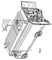
- Fig. 1 in perspektivischer Darstellung ein Kraftfahrzeug mit einer Beobachtungseinrichtung nach der Erfindung ;
- Fig. 2 in schematischer vergrößerter Darstellung die am Kraftfahrzeug gemäß Fig. 1 angeordnete Beobachtungseinrichtung in einer teilweise geschnittenen Seitenansicht ;
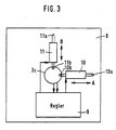
- Fig. 3 die Beobachtungseinrichtung nach Fig. 2 in einer Ansicht von unten.
- Wie Fig. 1 zu entnehmen, ist an einem Kraftfahrzeug 1 eine Beobachtungseinrichtung angeordnet, die einen durch eine Öffnung 2 im Dach des Kraftfahrzeuges 1 ausfahrbaren Teleskopmast 3 aufweist, an dessen oberem Ende eine Sensorplattform 4 schwenkbar angeordnet ist, in der nicht im einzelnen beschriebene übliche Beobachtungsgeräte, wie beispielsweise Fernsehkameras, Infrarotkameras und Richtmikrofone, angeordnet sind.
- Die Sensorplattform 4 ist mit dem Teleskopmast 3 über eine entsprechende Schwenkverbindung 4a so schwenkbar verbunden, daß sie feingerichtet werden kann.
- Der Teleskopmast 3 ist in der Nähe seines unteren Endes 3b über ein Kugelgelenk 7 mit einer mit dem Kraftfahrzeug 1 fest verbundenen Halterungsplatte 8 verbunden. Auf diese Weise ist der Teleskopmast 3 in allen senkrecht zum Fahrzeugboden stehenden Ebenen verschwenkbar. Am oberen Ende 3a des Teleskopmastes 3 sind dicht unterhalb des Sensorplattform 4 zwei Winkelgeber 5 und 6, beispielsweise Inklinometer, angeordnet, und zwar in zwei durch die Achse des Teleskopmastes 3 gehenden, senkrecht aufeinander stehenden Ebenen. Die Winkelgeber 5 und 6 messen den Winkel, den die Achse des Teleskopmastes 3 gegenüber der Vertikalen einnimmt und erzeugen entsprechende elektrische Signale, welche über angedeutette Leitungen 5a und 6a einem Regler 9 zugeführt werden, der, wenn die Winkelstellung des Teleskopmastes 3 von der Vertikalen abweicht, entsprechende Korrektursignale an zwei Stellglieder 10 und 11 abgibt Die Stellglieder 10 und 11 sind unterhalb der Halterungsplatte 8 angeordnet und jeweils über bewegliche Verbindungen 10a bzw. 11a mit der Halterungsplatte 8 und Verbindungen 10b bzw. 11b mit einer Halterung 3c am Fußpunkt des Teleskopmastes 3 verbunden. Die Stellglieder 10 und 11 sind in den gleichen Ebenen angeordnet wie die Winkelgeber 5 und 6 und wirken demnach in zwei zueinander senkrechten Richtungen A und B. Der Teleskopmast 3 ist somit über die Stellglieder 10 und 11 in Abhängigkeit von den
- vom Regler 9 gelieferten Signalen um die Aufhängung 7 so verschwenkbar, daß er unabhängig von der Stellung des Fahrzeuges 1 auf die Vertikale stabilisiert wird.
Claims (1)
- An einem Fahrzeug, insbesondere Kraftfahrzeug, angeordnete Beobachtungseinrichtung mit einem durch eine Öffnung im Fahrzeugdach ausfahrbaren Teleskopmast, an dessen oberem Ende eine Beobachtungsgeräte tragende Plattform schwenkbar angeordnet ist, dadurch gekennzeichnet, daß der Teleskopmast (3) in der Nähe seines unteren Endes (3b) über eine Bewegungen in zwei zueinander senkrecht stehenden, vertikalen Ebenen zulassende Aufhängung (7, 8) mit dem Fahrzeug (1) verbunden ist und daß eine den Teleskopmast (3) unabhängig von der Stellung des Fahrzeuges (1) auf die Vertikale ausrichtende Stabilisierungseinrichtung vorgesehen ist mit zwei in der Nähe des oberen Endes (3a) des Teleskopmastes (3) angeordneten, die in zwei zueinander senkrecht stehenden vertikalen Ebenen auftretenden Winkeldifferenzen zwischen der Richtung des Teleskopmastes (3) und der Vertikalen messenden und in elektrische Signale umwandelnden Winkelgebem (5, 6), die über einen Regelkreis (9) mit zwei am unteren Ende (3c) des Teleskopmastes (3) angreifenden in diesen vertikalen Ebenen wirksamen Stellgliedem (10, 11) verbunden sind.
Applications Claiming Priority (2)
| Application Number | Priority Date | Filing Date | Title |
|---|---|---|---|
| DE3317003 | 1983-05-10 | ||
| DE19833317003 DE3317003A1 (de) | 1983-05-10 | 1983-05-10 | An einem fahrzeug, insbesondere kraftfahrzeug, angeordnete beobachtungseinrichtung |
Publications (3)
| Publication Number | Publication Date |
|---|---|
| EP0128312A2 EP0128312A2 (de) | 1984-12-19 |
| EP0128312A3 EP0128312A3 (en) | 1987-02-04 |
| EP0128312B1 true EP0128312B1 (de) | 1989-11-23 |
Family
ID=6198606
Family Applications (1)
| Application Number | Title | Priority Date | Filing Date |
|---|---|---|---|
| EP84104728A Expired EP0128312B1 (de) | 1983-05-10 | 1984-04-27 | An einem Fahrzeug, insbesondere Kraftfahrzeug, angeordnete Beobachtungseinrichtung |
Country Status (2)
| Country | Link |
|---|---|
| EP (1) | EP0128312B1 (de) |
| DE (2) | DE3317003A1 (de) |
Cited By (1)
| Publication number | Priority date | Publication date | Assignee | Title |
|---|---|---|---|---|
| DE102015110693A1 (de) | 2015-05-12 | 2016-11-17 | GEMTEC GmbH | Anhängerbasiertes, mobiles Überwachungssystem |
Families Citing this family (19)
| Publication number | Priority date | Publication date | Assignee | Title |
|---|---|---|---|---|
| FR2577868B1 (fr) * | 1985-02-27 | 1987-05-15 | Lambolez Claude | Dispositif pour l'equipement d'un vehicule servant a la prise de vues d'un point eleve au-dessus du sol |
| FR2594763B1 (fr) * | 1986-02-24 | 1988-06-17 | Lambolez Claude | Dispositif pour l'equipement de mats telescopiques sur vehicules automobiles |
| US4815757A (en) * | 1986-04-24 | 1989-03-28 | Hamilton Mark L | Rapid development surveillance vehicle and method |
| US5121200A (en) * | 1990-07-06 | 1992-06-09 | Choi Seung Lyul | Travelling monitoring system for motor vehicles |
| DE9318170U1 (de) * | 1993-11-26 | 1994-02-10 | Steinheil Optronik GmbH, 85737 Ismaning | Vorrichtung zur Halterung einer Kamera |
| LU90186B1 (fr) | 1997-12-22 | 1999-06-24 | Communaute Europ Ce Batiment E | Dispositif d'analyse non destructive de plantes et véhicule comportant un tel dispositif embarqué |
| DE10046480A1 (de) | 2000-09-20 | 2002-03-28 | Krauss Maffei Wegmann Gmbh & C | Gepanzertes Fahrzeug, insbesondere Kampffahrzeug |
| KR100377957B1 (ko) * | 2000-12-18 | 2003-03-29 | 김천복 | 씨씨티비를 장착한 감시차량 |
| US6540198B2 (en) * | 2001-04-27 | 2003-04-01 | Engineered Support Systems, Inc. | Mast payload docking station |
| DE202006004291U1 (de) * | 2006-03-17 | 2007-07-19 | Klk Motorsport Gmbh | Transportvorrichtung für Kraftfahrzeuge |
| WO2011023198A1 (en) * | 2009-08-27 | 2011-03-03 | Falck Schmidt Defence Systems A/S | System for local vehicle surveillance |
| US7726690B1 (en) | 2009-11-05 | 2010-06-01 | Terrahawk, Llc | Vehicle for deploying a mobile surveillance module |
| GB2476970B (en) * | 2010-01-18 | 2012-06-13 | Altron Comm Equipment Ltd | Support |
| RU2565355C1 (ru) * | 2014-08-01 | 2015-10-20 | Российская Федерация, от имени которой выступает Министерство обороны Российской Федерации | Мобильный оптический телескоп |
| CN105015426A (zh) * | 2015-07-29 | 2015-11-04 | 深圳前海探鹿科技有限公司 | 一种车载投影仪 |
| CN105034953A (zh) * | 2015-08-13 | 2015-11-11 | 济南高达信息技术有限公司 | 一种全景行车旅游观光记录仪 |
| CN105398402B (zh) * | 2015-11-13 | 2018-05-25 | 周勤行 | 用于车顶全方位拍摄镜头的摆动机构 |
| CN205417428U (zh) * | 2015-12-14 | 2016-08-03 | 周勤行 | 用于车顶全方位拍摄镜头的垂直升降机构 |
| US10471904B2 (en) * | 2016-08-08 | 2019-11-12 | Toyota Motor Engineering & Manufacturing North America, Inc. | Systems and methods for adjusting the position of sensors of an automated vehicle |
Family Cites Families (5)
| Publication number | Priority date | Publication date | Assignee | Title |
|---|---|---|---|---|
| DE2033589A1 (de) * | 1970-07-07 | 1972-05-31 | Rheinstahl Ag | Beobachtungs- und Meßstand für optronische Geräte in einem Fahrzeug |
| DE7223740U (de) * | 1972-06-24 | 1973-03-01 | Kempkes H Hebezeugfabrik | Lampenträgermast und Lagerungsbeschlag für mit einer Flutlichtanlage auszurüstende Landfahrzeuge oder Schiffe |
| GB1521228A (en) * | 1976-11-15 | 1978-08-16 | Marconi Co Ltd | Stabilised platforms |
| GB1548266A (en) * | 1976-12-09 | 1979-07-11 | Elliott Brothers London Ltd | Image motion compensation system |
| GB2074129B (en) * | 1980-01-15 | 1984-07-11 | Marconi Co Ltd | Load handling apparatus |
-
1983
- 1983-05-10 DE DE19833317003 patent/DE3317003A1/de not_active Withdrawn
-
1984
- 1984-04-27 EP EP84104728A patent/EP0128312B1/de not_active Expired
- 1984-04-27 DE DE8484104728T patent/DE3480565D1/de not_active Expired
Cited By (1)
| Publication number | Priority date | Publication date | Assignee | Title |
|---|---|---|---|---|
| DE102015110693A1 (de) | 2015-05-12 | 2016-11-17 | GEMTEC GmbH | Anhängerbasiertes, mobiles Überwachungssystem |
Also Published As
| Publication number | Publication date |
|---|---|
| EP0128312A3 (en) | 1987-02-04 |
| EP0128312A2 (de) | 1984-12-19 |
| DE3480565D1 (en) | 1989-12-28 |
| DE3317003A1 (de) | 1984-11-15 |
Similar Documents
| Publication | Publication Date | Title |
|---|---|---|
| EP0128312A2 (de) | An einem Fahrzeug, insbesondere Kraftfahrzeug, angeordnete Beobachtungseinrichtung | |
| WO1995006178A1 (de) | Grossmanipulator, insbesondere für autobetonpumpen, sowie verfahren zu dessen handhabung | |
| DE2746794B2 (de) | Vorrichtung zur Positionierung des Tragrahmens eines Verladegerätes für quaderförmiges Strickgut | |
| DE2752319A1 (de) | Vorrichtung zum erkennen einer evtl. verformung eines bestimmten gestells oder aufbaus, wie einem fahrgestell oder einer selbsttragenden karosserie eines kraftfahrzeuges | |
| DE2849144A1 (de) | Teleskopauslegerkran mit zusatzausleger | |
| AT404702B (de) | Verladevorrichtung für eine sperrige last, z. b. einen container | |
| WO2020182592A1 (de) | Kran sowie vorrichtung zu dessen steuerung | |
| DE4428734A1 (de) | Verfahren zur Bearbeitung eines Objektes, insbesondere eines Flugzeugs | |
| DE2310767B2 (de) | Einrichtung zur Stabilisierung einer in einem Kardanrahmen aufgehängten Plattform | |
| WO2020104273A1 (de) | Kran mit einer antikollisionseinrichtung sowie verfahren zum einrichten einer solchen antikollisionseinrichtung | |
| AT500429B1 (de) | Fahrzeug mit einer arbeitsbühne | |
| DE69520556T2 (de) | Vorrichtung zur Detektion der Verschiebung sich bewegender Teile in industriellen Apparaten | |
| US4629369A (en) | Manipulator transporter | |
| DE2649490C2 (de) | Sicherheitseinrichtung für einen aus mehreren gegeneinander beweglichen Abschnitten bestehenden Ladearm | |
| EP0671600A2 (de) | Winkelmessvorrichtung | |
| DE1773600C3 (de) | Doppler-Trägheits-Navigationsanlage | |
| EP0753479B1 (de) | Fahrzeug, insbesondere Kampffahrzeug mit einer Hubplattform | |
| DE102008014140A1 (de) | Raupenkran sowie Verfahren zur Einstellung einer Grund-Arbeitsposition eines derartigen Raupenkrans | |
| DE3234020A1 (de) | Anordnung zum verschwenken eines anbauhalters der ausruestung eines hydraulikbaggers | |
| DE19731587A1 (de) | Teleskopkran mit wippbarem Hilfsausleger | |
| DE3429214A1 (de) | Zusatzausruestung zum senkrechten bewegen von lasten oder anbaugeraeten fuer radlader | |
| DE4405644A1 (de) | Verfahren und Vorrichtung zur Ausrichtung und Stabilisierung von Antennen für Satellitendatenempfang | |
| DE102017110006B4 (de) | Außenwinde für einen Hubschrauber mit Einrichtungen zur Stabilisierung einer an die Außenwinde angehängten Außenlast und Hubschrauber mit einer solchen Außenwinde | |
| DE10056706B4 (de) | Befestigungsvorrichtung für Antennenmasten | |
| DE1127564B (de) | Fahrbare und hoehenverstellbare Arbeitsplattform mit Gelenkmast |
Legal Events
| Date | Code | Title | Description |
|---|---|---|---|
| PUAI | Public reference made under article 153(3) epc to a published international application that has entered the european phase |
Free format text: ORIGINAL CODE: 0009012 |
|
| AK | Designated contracting states |
Designated state(s): BE DE FR GB NL |
|
| PUAL | Search report despatched |
Free format text: ORIGINAL CODE: 0009013 |
|
| AK | Designated contracting states |
Kind code of ref document: A3 Designated state(s): BE DE FR GB NL |
|
| 17P | Request for examination filed |
Effective date: 19870309 |
|
| 17Q | First examination report despatched |
Effective date: 19890102 |
|
| GRAA | (expected) grant |
Free format text: ORIGINAL CODE: 0009210 |
|
| AK | Designated contracting states |
Kind code of ref document: B1 Designated state(s): BE DE FR GB NL |
|
| REF | Corresponds to: |
Ref document number: 3480565 Country of ref document: DE Date of ref document: 19891228 |
|
| GBT | Gb: translation of ep patent filed (gb section 77(6)(a)/1977) | ||
| ET | Fr: translation filed | ||
| PLBE | No opposition filed within time limit |
Free format text: ORIGINAL CODE: 0009261 |
|
| STAA | Information on the status of an ep patent application or granted ep patent |
Free format text: STATUS: NO OPPOSITION FILED WITHIN TIME LIMIT |
|
| 26N | No opposition filed | ||
| PGFP | Annual fee paid to national office [announced via postgrant information from national office to epo] |
Ref country code: BE Payment date: 19920428 Year of fee payment: 9 |
|
| PGFP | Annual fee paid to national office [announced via postgrant information from national office to epo] |
Ref country code: FR Payment date: 19920429 Year of fee payment: 9 |
|
| PG25 | Lapsed in a contracting state [announced via postgrant information from national office to epo] |
Ref country code: BE Effective date: 19930430 |
|
| BERE | Be: lapsed |
Owner name: WEGMANN & CO. G.M.B.H. Effective date: 19930430 |
|
| PG25 | Lapsed in a contracting state [announced via postgrant information from national office to epo] |
Ref country code: FR Effective date: 19931229 |
|
| REG | Reference to a national code |
Ref country code: FR Ref legal event code: ST |
|
| PGFP | Annual fee paid to national office [announced via postgrant information from national office to epo] |
Ref country code: GB Payment date: 19990414 Year of fee payment: 16 |
|
| PGFP | Annual fee paid to national office [announced via postgrant information from national office to epo] |
Ref country code: NL Payment date: 19990429 Year of fee payment: 16 |
|
| PGFP | Annual fee paid to national office [announced via postgrant information from national office to epo] |
Ref country code: DE Payment date: 19990510 Year of fee payment: 16 |
|
| PG25 | Lapsed in a contracting state [announced via postgrant information from national office to epo] |
Ref country code: GB Free format text: LAPSE BECAUSE OF NON-PAYMENT OF DUE FEES Effective date: 20000427 |
|
| PG25 | Lapsed in a contracting state [announced via postgrant information from national office to epo] |
Ref country code: NL Free format text: LAPSE BECAUSE OF NON-PAYMENT OF DUE FEES Effective date: 20001101 |
|
| GBPC | Gb: european patent ceased through non-payment of renewal fee |
Effective date: 20000427 |
|
| NLV4 | Nl: lapsed or anulled due to non-payment of the annual fee |
Effective date: 20001101 |
|
| PG25 | Lapsed in a contracting state [announced via postgrant information from national office to epo] |
Ref country code: DE Free format text: LAPSE BECAUSE OF NON-PAYMENT OF DUE FEES Effective date: 20010201 |