EP0128257A1 - Verfahren zum Zuführen von Stangen bei einer Drehbank - Google Patents
Verfahren zum Zuführen von Stangen bei einer Drehbank Download PDFInfo
- Publication number
- EP0128257A1 EP0128257A1 EP83810243A EP83810243A EP0128257A1 EP 0128257 A1 EP0128257 A1 EP 0128257A1 EP 83810243 A EP83810243 A EP 83810243A EP 83810243 A EP83810243 A EP 83810243A EP 0128257 A1 EP0128257 A1 EP 0128257A1
- Authority
- EP
- European Patent Office
- Prior art keywords
- bar
- channel
- parts
- new
- refueling
- Prior art date
- Legal status (The legal status is an assumption and is not a legal conclusion. Google has not performed a legal analysis and makes no representation as to the accuracy of the status listed.)
- Granted
Links
Images


Classifications
-
- B—PERFORMING OPERATIONS; TRANSPORTING
- B23—MACHINE TOOLS; METAL-WORKING NOT OTHERWISE PROVIDED FOR
- B23B—TURNING; BORING
- B23B13/00—Arrangements for automatically conveying or chucking or guiding stock
- B23B13/02—Arrangements for automatically conveying or chucking or guiding stock for turning-machines with a single working-spindle
- B23B13/027—Feeding by pistons under fluid-pressure
-
- B—PERFORMING OPERATIONS; TRANSPORTING
- B23—MACHINE TOOLS; METAL-WORKING NOT OTHERWISE PROVIDED FOR
- B23B—TURNING; BORING
- B23B13/00—Arrangements for automatically conveying or chucking or guiding stock
- B23B13/12—Accessories, e.g. stops, grippers
- B23B13/128—Stock rest handling devices, e.g. ejectors
-
- Y—GENERAL TAGGING OF NEW TECHNOLOGICAL DEVELOPMENTS; GENERAL TAGGING OF CROSS-SECTIONAL TECHNOLOGIES SPANNING OVER SEVERAL SECTIONS OF THE IPC; TECHNICAL SUBJECTS COVERED BY FORMER USPC CROSS-REFERENCE ART COLLECTIONS [XRACs] AND DIGESTS
- Y10—TECHNICAL SUBJECTS COVERED BY FORMER USPC
- Y10T—TECHNICAL SUBJECTS COVERED BY FORMER US CLASSIFICATION
- Y10T82/00—Turning
- Y10T82/25—Lathe
- Y10T82/2514—Lathe with work feeder or remover
- Y10T82/2516—Magazine type
- Y10T82/2518—Bar feeder
Definitions
- the present invention relates to a method of supplying a lathe with bars to be machined, said bars being held and guided in a bar guide device. It also relates to a bar feeder for a machining bar with a channel-shaped bar guide device in which the bar to be machined is rotated in oil forming hydrodynamic bearing, the advancement of the bar in the channel being produced by a hydraulically controlled push piston which comes to press and support the rear of the bar.
- the object of the present invention is to shorten the refueling operation of the machine to increase the production rate.
- the refueling cycle is shortened by the fact that the new bar is introduced into the bar guide device during the machining operation of the last part in the end of the previous bar and also by the fact that the bar falls previous is ejected by the advance of the new bar against the rear of this fall.
- the bar guide device is a channel in two parts which, during refueling, are spaced apart radially from one another to allow lateral introduction of the new bar to be machined.
- the chute ejection devices normally provided, can be eliminated by the fact that it is the advance of the new bar in the bar guide device which causes the ejection of the chute, this advance being produced by a piston - hydraulically operated pusher.
- the refueling method according to the invention makes it possible to reduce the dead times during refueling by the fact that the new bar is introduced into its guide channel during the machining of the last part in the end of the previous bar and to remove the fall ejection devices normally provided for this purpose, this ejection being produced by pressing the new bar against the rear of the fall when the clamping unit is opened. It also appears from the previous description of the various operations that the refueling method according to the invention is advantageously but not necessarily applied to a numerically controlled machine, because of the flexibility of control of such a machine.
- FIG. 4 shows a schematic longitudinal view of a feeder of a lathe in bars to be machined according to the invention, operating according to the method described above.
- the tanker has a channel 5 in two parts 5a and 5b ( Figure 7).
- the channel 5 is mounted on supports 6.
- the upper part 5a of the channel is assembled with return pistons 7 making it possible to lift this part and to separate it from the lower part 5b.
- Pressure pistons 8 make it possible to close the channel in a sealed manner by applying with high pressure the part 5a against the lower part 5b of the channel.
- Cams 9 allow, during refueling, to introduce laterally a new bar to be machined between the parts 5a and 5b separated from the channel.
- the channel 5 is a bar guide device in which a hydraulically controlled push piston 4 (FIG.
- the push piston 4 is first removed by vacuum towards the rear of the feeder, so that it is also necessary to seal the channel preventing air from entering it during removal of the piston, this sealing being ensured by the flatness and the pressure of the surfaces in contact. Seals can be used, but they are not necessarily necessary.
- the feeder is located in the extension of the axis of the headstock 10 of the lathe and in the immediate vicinity thereof.
- a hydraulic distribution system 11 allows the control of the pressure 8 and return 7 pistons, of the push piston 4 and the supply of oil to the closed channel.
- Figure 5 shows a sectional view of the channel 5 with a pressure piston 8. We recognize the bar 1 in the channel 5 and the two parts 5a and 5b of this channel.
- Figure 6 shows a sectional view of the pistons 7 and 8 and the channel 5.
- the return piston 7 is coupled to the upper part 5a of the channel 5 by a U-shaped bracket 13 extending at the upper part and on two sides side of part 5a.
- the stirrup is coupled to this part 5a by a cut-out opening in which is engaged a pin 12 secured to part 5a.
- This arrangement allows the removal of part 5a of the channel when changing the diameter of the bar to be machined.
- the pressure pistons 8 are without pressure and the pistons 7 are withdrawn by hydraulic pressure, these pistons lifting the part 5a of the channel to open the latter.
- the figure shows proximity sensors 21 which deliver a signal indicating that the channel is closed.
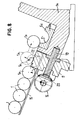
- FIG. 7 shows an end view of the tanker according to the invention.
- the channel 5 comprises the part 5b fixedly mounted in a frame 14 of the refueler and the mobile part 5a on which the pressure pistons 8 act and which, during the refueling is raised by the return pistons to allow the lateral introduction of 'a new bar in the fixed part 5b.
- the bars 1 to be supplied are arranged side by side on an apron 15 forming an inclined plane. The axis of these bars is parallel to that of the channel 5.
- the first bar, seen from the channel is stopped in the waiting position, against a bearing surface of the cams 9 each driven by a revolution by a motor 16 during refueling.
- a stop 22 adjustable according to the diameter of the bars to be machined is provided on the bulkhead 15 in the vicinity of the cam 9.
- FIG. 7 also shows that centering pins 17 are provided between the stirrups 13 and the centering pads of the channel 18. These centering pins are intended to ensure perfect alignment of the two parts of the channel when the latter is closed.
- Figure 8 shows that the cam 9 is mounted on a shaft 19 and rotated by a bevel gear 20 from the motor 16 and Figure 9 shows the configuration of this cam 9.
- the first bar 1p is in the standby position against a bearing surface A perpendicular the axis of the cam.
- the cam starts to rotate and its helical surface H allows a progressive and smooth descent of the bundle of bars 1, 1p in the direction of the channel 5.
- the first bar 1p is gradually introduced against the adjustable stop 22.
- the cam 9 continuing to rotate, the second bar remains in contact with the bearing surface A and the rise B of the cam gradually raises the bar 1p to a level allowing it to pass by rolling over the stop 22, the part of the frame 14 between the stop 22 and the fixed part of the channel 5b and to fall laterally in this part of the channel.
- the feeder described above makes it possible to perform the functions indicated in connection with the refueling process, so that it leads to a reduction in times dead and an increased production rate.
- the invention is not limited to the embodiment of the supply vessel described above.
- the storage of the bars on an inclined plane and the loading of the bars by a cam can be carried out differently.
- the same is true of the means for exerting the closing pressure of the channel and the withdrawal of the upper part of the latter.
Priority Applications (4)
| Application Number | Priority Date | Filing Date | Title |
|---|---|---|---|
| EP83810243A EP0128257B1 (de) | 1983-06-06 | 1983-06-06 | Verfahren zum Zuführen von Stangen bei einer Drehbank |
| DE8383810243T DE3371047D1 (en) | 1983-06-06 | 1983-06-06 | Bar feeding process for a lathe |
| US06/616,169 US4640157A (en) | 1983-06-06 | 1984-06-01 | Process for loading a lathe with bars to be machined and loading device for carrying out of the process |
| ES533117A ES533117A0 (es) | 1983-06-06 | 1984-06-05 | Procedimiento con su dispositivo correspondiente, de abastecimiento de un torno de mecanizacion de barras |
Applications Claiming Priority (1)
| Application Number | Priority Date | Filing Date | Title |
|---|---|---|---|
| EP83810243A EP0128257B1 (de) | 1983-06-06 | 1983-06-06 | Verfahren zum Zuführen von Stangen bei einer Drehbank |
Publications (2)
| Publication Number | Publication Date |
|---|---|
| EP0128257A1 true EP0128257A1 (de) | 1984-12-19 |
| EP0128257B1 EP0128257B1 (de) | 1987-04-22 |
Family
ID=8191554
Family Applications (1)
| Application Number | Title | Priority Date | Filing Date |
|---|---|---|---|
| EP83810243A Expired EP0128257B1 (de) | 1983-06-06 | 1983-06-06 | Verfahren zum Zuführen von Stangen bei einer Drehbank |
Country Status (4)
| Country | Link |
|---|---|
| US (1) | US4640157A (de) |
| EP (1) | EP0128257B1 (de) |
| DE (1) | DE3371047D1 (de) |
| ES (1) | ES533117A0 (de) |
Cited By (2)
| Publication number | Priority date | Publication date | Assignee | Title |
|---|---|---|---|---|
| US4640157A (en) * | 1983-06-06 | 1987-02-03 | Sameca S.A. | Process for loading a lathe with bars to be machined and loading device for carrying out of the process |
| EP0340286B1 (de) * | 1987-11-09 | 1993-06-16 | Kurt Jauch | Drehautomat zum verarbeiten von werkstoffstangen |
Families Citing this family (4)
| Publication number | Priority date | Publication date | Assignee | Title |
|---|---|---|---|---|
| DE3528743A1 (de) * | 1985-08-10 | 1987-02-12 | Kurt Breuning | Materialstangenzufuehrvorrichtung |
| US4753563A (en) * | 1987-07-06 | 1988-06-28 | Mcinerney Incorporated | Welded tube seam positioner and method |
| DE4431814A1 (de) * | 1994-09-07 | 1996-03-14 | Index Werke Kg Hahn & Tessky | Automatische Werkstoffstangen-Zuführeinrichtung für Werkzeugmaschinen, insbesondere Drehautomaten |
| US5617769A (en) * | 1994-10-14 | 1997-04-08 | Hardinge Brothers, Inc. | Thermally compliant bar feeding machine |
Citations (9)
| Publication number | Priority date | Publication date | Assignee | Title |
|---|---|---|---|---|
| US2577203A (en) * | 1946-04-26 | 1951-12-04 | Lipe Rollway Corp | Bar feed loader for metalworking machines |
| GB691087A (en) * | 1951-03-12 | 1953-05-06 | H W Ward & Co Ltd | Stock-bar feed mechanism for lathes |
| GB895273A (en) * | 1960-07-05 | 1962-05-02 | Birfield Eng Ltd | Improvements in or relating to bar feeds for automatic lathes and other machine tools |
| US3095771A (en) * | 1957-05-15 | 1963-07-02 | Ratby Engineering Company Ltd | Stop devices for facilitating automatic feeding of bar stock into machine tools |
| DE1402204A1 (de) * | 1958-01-10 | 1969-11-06 | Index Werke Kg Hahn & Tessky | Selbsttaetige Nachschubeinrichtung zum Nachschieben von Materialstangen an selbsttaetigen Drehbaenken |
| GB1213973A (en) * | 1966-09-07 | 1970-11-25 | Gearaide Ltd | A bar feeding mechanism for machine tools |
| DE1918843A1 (de) * | 1969-04-14 | 1970-12-10 | Monforts Fa A | Stangenautomat mit numerisch gesteuerter Stangenfuehrung |
| NL7713034A (en) * | 1977-11-25 | 1979-05-29 | Sijtze Marcelis Jouta | Automatic lathe bar feed mechanism - feeds via grip tongs driven by machine main motor, with movable stop providing for excess material removal |
| EP0071518A1 (de) * | 1981-07-23 | 1983-02-09 | Mitac | Stangennachschubeinrichtung |
Family Cites Families (5)
| Publication number | Priority date | Publication date | Assignee | Title |
|---|---|---|---|---|
| AU425908B2 (en) * | 1968-04-10 | 1972-07-10 | Rast Products Pty. Ltd | Improvements in and relating tothe bar feed tubes of lathes |
| US4445697A (en) * | 1980-05-09 | 1984-05-01 | Kenmar Export Ltd. | Collet |
| US4406190A (en) * | 1980-05-16 | 1983-09-27 | White-Bsa Tools Limited | Bar stock feed apparatus for a machine tool |
| JPS57194802A (en) * | 1981-05-22 | 1982-11-30 | Azuma Shimamoto Kk | Material feeder of machine tool |
| EP0128257B1 (de) * | 1983-06-06 | 1987-04-22 | Sameca S.A. | Verfahren zum Zuführen von Stangen bei einer Drehbank |
-
1983
- 1983-06-06 EP EP83810243A patent/EP0128257B1/de not_active Expired
- 1983-06-06 DE DE8383810243T patent/DE3371047D1/de not_active Expired
-
1984
- 1984-06-01 US US06/616,169 patent/US4640157A/en not_active Expired - Fee Related
- 1984-06-05 ES ES533117A patent/ES533117A0/es active Granted
Patent Citations (9)
| Publication number | Priority date | Publication date | Assignee | Title |
|---|---|---|---|---|
| US2577203A (en) * | 1946-04-26 | 1951-12-04 | Lipe Rollway Corp | Bar feed loader for metalworking machines |
| GB691087A (en) * | 1951-03-12 | 1953-05-06 | H W Ward & Co Ltd | Stock-bar feed mechanism for lathes |
| US3095771A (en) * | 1957-05-15 | 1963-07-02 | Ratby Engineering Company Ltd | Stop devices for facilitating automatic feeding of bar stock into machine tools |
| DE1402204A1 (de) * | 1958-01-10 | 1969-11-06 | Index Werke Kg Hahn & Tessky | Selbsttaetige Nachschubeinrichtung zum Nachschieben von Materialstangen an selbsttaetigen Drehbaenken |
| GB895273A (en) * | 1960-07-05 | 1962-05-02 | Birfield Eng Ltd | Improvements in or relating to bar feeds for automatic lathes and other machine tools |
| GB1213973A (en) * | 1966-09-07 | 1970-11-25 | Gearaide Ltd | A bar feeding mechanism for machine tools |
| DE1918843A1 (de) * | 1969-04-14 | 1970-12-10 | Monforts Fa A | Stangenautomat mit numerisch gesteuerter Stangenfuehrung |
| NL7713034A (en) * | 1977-11-25 | 1979-05-29 | Sijtze Marcelis Jouta | Automatic lathe bar feed mechanism - feeds via grip tongs driven by machine main motor, with movable stop providing for excess material removal |
| EP0071518A1 (de) * | 1981-07-23 | 1983-02-09 | Mitac | Stangennachschubeinrichtung |
Cited By (2)
| Publication number | Priority date | Publication date | Assignee | Title |
|---|---|---|---|---|
| US4640157A (en) * | 1983-06-06 | 1987-02-03 | Sameca S.A. | Process for loading a lathe with bars to be machined and loading device for carrying out of the process |
| EP0340286B1 (de) * | 1987-11-09 | 1993-06-16 | Kurt Jauch | Drehautomat zum verarbeiten von werkstoffstangen |
Also Published As
| Publication number | Publication date |
|---|---|
| ES8503540A1 (es) | 1985-04-01 |
| US4640157A (en) | 1987-02-03 |
| DE3371047D1 (en) | 1987-05-27 |
| ES533117A0 (es) | 1985-04-01 |
| EP0128257B1 (de) | 1987-04-22 |
Similar Documents
| Publication | Publication Date | Title |
|---|---|---|
| EP2033725B1 (de) | Vorrichtung zum universellen automatischen Zuführen und Entladen von Werkstücken für Werkzeugmaschine | |
| EP0891830B1 (de) | Stangenzuführvorrichtung für eine Werkzeugmaschine, insbesondere einen Drehautomaten | |
| FR2488169A1 (fr) | Ensemble d'un coulisseau et d'un porte-outil pour tour vertical ou machine analogue | |
| EP0128257B1 (de) | Verfahren zum Zuführen von Stangen bei einer Drehbank | |
| EP0356389B1 (de) | Antriebsvorrichtung für eine Mehrspindelbearbeitungsmaschine | |
| FR2485423A1 (fr) | Machine de meulage de pointes de forets | |
| EP0121638B1 (de) | Stangenführungsvorrichtung für Mehrspindeldrehmaschinen | |
| FR2459700A1 (fr) | Machine-outil a broche principale creuse et a mecanisme d'avance de barre a usiner associe | |
| EP0180686B1 (de) | Stangenführungsvorrichtung für Mehrspindeldrehmaschine | |
| FR2474917A1 (fr) | Dispositif de transfert automatique d'objets | |
| EP0108182B1 (de) | Stangenführungsvorrichtung für Mehrspindel-Drehmaschinen | |
| FR2526699A1 (fr) | Appareil et procede pour realiser la commande programmee de fonctions de travail, notamment pour le soudage d'elements de batterie | |
| EP0179024B1 (de) | Montagevorrichtung für eine Spannzange zum Spannen eines Werkstückes in einer Werkzeugmaschine | |
| EP0320357B1 (de) | Maschine zum Entfernen des Abstandsdrahtes von Kernbrennstäben | |
| BE893239A (fr) | Machine pour le traitement de bouteilles ou autres contenants | |
| EP0638007A1 (de) | Mehrspindeldrehautomat | |
| CH676939A5 (en) | Bar feed magazine with split bearings - feeds of bar stock into head stock of machine tool | |
| FR2497701A1 (fr) | Dispositif d'alimentation continue d'une machine pour la fabrication de pieces a partir d'un fil ou d'une barre | |
| FR2546090A1 (fr) | Dispositif pour charger un tour frontal | |
| FR2478513A1 (fr) | Dispositif d'alimentation automatique de barres dans une machine-outil | |
| FR2622129A1 (fr) | Machine de conformation d'un troncon de fil ou de tube par pliages successifs | |
| EP0268327A1 (de) | Schneidvorrichtung für ein Metallrohr durch Aufspreizen von Sektoren eines Werkzeuges für eine automatische Mehrzweckmaschine | |
| CH552442A (fr) | Machine-outil a changement automatique d'outil. | |
| FR2515083A1 (fr) | Dispositif automatique d'amenee et d'evacuation des pieces a usiner sur une fraiseuse rotative | |
| EP3110585A1 (de) | Drehautomaten, steuereinheit für drehautomaten und nachrüstungsverfahren für eine derartige einheit |
Legal Events
| Date | Code | Title | Description |
|---|---|---|---|
| PUAI | Public reference made under article 153(3) epc to a published international application that has entered the european phase |
Free format text: ORIGINAL CODE: 0009012 |
|
| 17P | Request for examination filed |
Effective date: 19840525 |
|
| AK | Designated contracting states |
Designated state(s): AT BE CH DE FR GB IT LI LU NL SE |
|
| RBV | Designated contracting states (corrected) |
Designated state(s): CH DE FR GB IT LI SE |
|
| 17Q | First examination report despatched |
Effective date: 19860418 |
|
| GRAA | (expected) grant |
Free format text: ORIGINAL CODE: 0009210 |
|
| AK | Designated contracting states |
Kind code of ref document: B1 Designated state(s): CH DE FR GB IT LI SE |
|
| ITF | It: translation for a ep patent filed |
Owner name: BARZANO' E ZANARDO MILANO S.P.A. |
|
| REF | Corresponds to: |
Ref document number: 3371047 Country of ref document: DE Date of ref document: 19870527 |
|
| PLBI | Opposition filed |
Free format text: ORIGINAL CODE: 0009260 |
|
| 26 | Opposition filed |
Opponent name: TRAUB AG Effective date: 19880122 |
|
| PGFP | Annual fee paid to national office [announced via postgrant information from national office to epo] |
Ref country code: SE Payment date: 19890509 Year of fee payment: 7 |
|
| PGFP | Annual fee paid to national office [announced via postgrant information from national office to epo] |
Ref country code: FR Payment date: 19890518 Year of fee payment: 7 |
|
| PGFP | Annual fee paid to national office [announced via postgrant information from national office to epo] |
Ref country code: GB Payment date: 19890531 Year of fee payment: 7 |
|
| PGFP | Annual fee paid to national office [announced via postgrant information from national office to epo] |
Ref country code: CH Payment date: 19890616 Year of fee payment: 7 |
|
| ITTA | It: last paid annual fee | ||
| PGFP | Annual fee paid to national office [announced via postgrant information from national office to epo] |
Ref country code: DE Payment date: 19890710 Year of fee payment: 7 |
|
| RDAG | Patent revoked |
Free format text: ORIGINAL CODE: 0009271 |
|
| STAA | Information on the status of an ep patent application or granted ep patent |
Free format text: STATUS: PATENT REVOKED |
|
| REG | Reference to a national code |
Ref country code: CH Ref legal event code: PL |
|
| 27W | Patent revoked |
Effective date: 19900308 |
|
| GBPR | Gb: patent revoked under art. 102 of the ep convention designating the uk as contracting state | ||
| EUG | Se: european patent has lapsed |
Ref document number: 83810243.2 Effective date: 19900905 |