EP0128154B1 - Mit wärmeleitfähiger paste oder flüssigkeit gefüllter flachbeutel - Google Patents
Mit wärmeleitfähiger paste oder flüssigkeit gefüllter flachbeutel Download PDFInfo
- Publication number
- EP0128154B1 EP0128154B1 EP83903492A EP83903492A EP0128154B1 EP 0128154 B1 EP0128154 B1 EP 0128154B1 EP 83903492 A EP83903492 A EP 83903492A EP 83903492 A EP83903492 A EP 83903492A EP 0128154 B1 EP0128154 B1 EP 0128154B1
- Authority
- EP
- European Patent Office
- Prior art keywords
- bag
- paste
- flat bag
- foil sheets
- pockets
- Prior art date
- Legal status (The legal status is an assumption and is not a legal conclusion. Google has not performed a legal analysis and makes no representation as to the accuracy of the status listed.)
- Expired
Links
- 239000007788 liquid Substances 0.000 title claims description 13
- 239000011888 foil Substances 0.000 claims description 12
- 239000000463 material Substances 0.000 claims description 4
- 229910052751 metal Inorganic materials 0.000 claims description 3
- 239000002184 metal Substances 0.000 claims description 3
- 239000005030 aluminium foil Substances 0.000 claims 1
- 229910052782 aluminium Inorganic materials 0.000 abstract description 2
- XAGFODPZIPBFFR-UHFFFAOYSA-N aluminium Chemical compound [Al] XAGFODPZIPBFFR-UHFFFAOYSA-N 0.000 abstract description 2
- 239000004411 aluminium Substances 0.000 abstract 1
- 238000003466 welding Methods 0.000 description 3
- 230000006978 adaptation Effects 0.000 description 1
- 238000004026 adhesive bonding Methods 0.000 description 1
- 239000004020 conductor Substances 0.000 description 1
- 238000001816 cooling Methods 0.000 description 1
- 230000000694 effects Effects 0.000 description 1
- 230000002349 favourable effect Effects 0.000 description 1
- 239000000945 filler Substances 0.000 description 1
- 230000017525 heat dissipation Effects 0.000 description 1
- 229910001338 liquidmetal Inorganic materials 0.000 description 1
- 230000007774 longterm Effects 0.000 description 1
- 238000000034 method Methods 0.000 description 1
- 239000007787 solid Substances 0.000 description 1
- 239000000126 substance Substances 0.000 description 1
Images
Classifications
-
- H—ELECTRICITY
- H05—ELECTRIC TECHNIQUES NOT OTHERWISE PROVIDED FOR
- H05K—PRINTED CIRCUITS; CASINGS OR CONSTRUCTIONAL DETAILS OF ELECTRIC APPARATUS; MANUFACTURE OF ASSEMBLAGES OF ELECTRICAL COMPONENTS
- H05K7/00—Constructional details common to different types of electric apparatus
- H05K7/20—Modifications to facilitate cooling, ventilating, or heating
- H05K7/2039—Modifications to facilitate cooling, ventilating, or heating characterised by the heat transfer by conduction from the heat generating element to a dissipating body
- H05K7/20436—Inner thermal coupling elements in heat dissipating housings, e.g. protrusions or depressions integrally formed in the housing
- H05K7/20445—Inner thermal coupling elements in heat dissipating housings, e.g. protrusions or depressions integrally formed in the housing the coupling element being an additional piece, e.g. thermal standoff
- H05K7/20454—Inner thermal coupling elements in heat dissipating housings, e.g. protrusions or depressions integrally formed in the housing the coupling element being an additional piece, e.g. thermal standoff with a conformable or flexible structure compensating for irregularities, e.g. cushion bags, thermal paste
-
- F—MECHANICAL ENGINEERING; LIGHTING; HEATING; WEAPONS; BLASTING
- F28—HEAT EXCHANGE IN GENERAL
- F28F—DETAILS OF HEAT-EXCHANGE AND HEAT-TRANSFER APPARATUS, OF GENERAL APPLICATION
- F28F3/00—Plate-like or laminated elements; Assemblies of plate-like or laminated elements
- F28F3/12—Elements constructed in the shape of a hollow panel, e.g. with channels
-
- Y—GENERAL TAGGING OF NEW TECHNOLOGICAL DEVELOPMENTS; GENERAL TAGGING OF CROSS-SECTIONAL TECHNOLOGIES SPANNING OVER SEVERAL SECTIONS OF THE IPC; TECHNICAL SUBJECTS COVERED BY FORMER USPC CROSS-REFERENCE ART COLLECTIONS [XRACs] AND DIGESTS
- Y10—TECHNICAL SUBJECTS COVERED BY FORMER USPC
- Y10T—TECHNICAL SUBJECTS COVERED BY FORMER US CLASSIFICATION
- Y10T428/00—Stock material or miscellaneous articles
- Y10T428/13—Hollow or container type article [e.g., tube, vase, etc.]
- Y10T428/1334—Nonself-supporting tubular film or bag [e.g., pouch, envelope, packet, etc.]
- Y10T428/1338—Elemental metal containing
-
- Y—GENERAL TAGGING OF NEW TECHNOLOGICAL DEVELOPMENTS; GENERAL TAGGING OF CROSS-SECTIONAL TECHNOLOGIES SPANNING OVER SEVERAL SECTIONS OF THE IPC; TECHNICAL SUBJECTS COVERED BY FORMER USPC CROSS-REFERENCE ART COLLECTIONS [XRACs] AND DIGESTS
- Y10—TECHNICAL SUBJECTS COVERED BY FORMER USPC
- Y10T—TECHNICAL SUBJECTS COVERED BY FORMER US CLASSIFICATION
- Y10T428/00—Stock material or miscellaneous articles
- Y10T428/23—Sheet including cover or casing
- Y10T428/239—Complete cover or casing
Definitions
- the invention relates to a flat bag (11) which is filled with thermally conductive paste (18) or liquid and is composed of foils (14, 15) and is closed on all sides.
- the heat transfer resistance between two solid bodies is lower, the thinner the air-filled space or gap between the contact surfaces of the bodies.
- To reduce the heat transfer resistance between bodies that are only in temporary contact with one another it is therefore known to grind or polish the contact surfaces. If this is too complex, it is also known to fill the gap between the contact surfaces with a thermal contact paste. Due to its considerably higher thermal conductivity than air, this reduces the heat transfer resistance of the respective column.
- Thermal contact pastes are relatively cumbersome to use because the pastes are highly viscous and sticky. An attempt was therefore made to improve the properties by enclosing the paste in a bag.
- US Pat. No. 3,586,102 discloses such a plastic bag which is used to produce thermal bridges between the components of a printed circuit board and a heat dissipation plate.
- a plastic bag is known from IBM Disclosure Bulletin, Volume 19, No. 8, January 1977, page 3127, which is filled with a liquid metal. This pouch also serves to dissipate the heat from electrical components to a heat sink.
- the invention is described in more detail below, for example, using a single double figure.
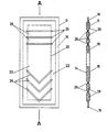
- the figure shows a top view on the left and a section along the line A-A through a flat bag 11 on the right.
- This bag 11 is formed, for example, from two foils 14 and 15 by gluing or welding. 16 denotes the welding edge which hermetically seals the bag on all sides.
- the foils 14 and 15 are made of a highly thermally conductive material, in particular of metal, e.g. B. aluminum. They are relatively thin (e.g. 1/10 mm) and cuddly. Inside the bag 11 is a good heat-conductive paste 18.
- a range limit 20 is shown in dashed lines.
- the inner region 23 with respect to this limit serves to fill the gap between two rigid bodies for the purpose of improved heat exchange between these bodies.
- the area 22 between the boundary 20 and the welding edge 16, however, must not lie in the gap, but must have space for expansion. Its inflatable volume is dimensioned such that it can hold all of the thermal paste 18 contained in the bag 11.
- the bags 11 are preferably used in electronic racks with liquid cooling, as are known, for example, from Swiss Patent Application No. 3,683 / 82-0. With these racks, the task is to establish a flawless and long-term constant thermal contact between tubes inside the frame for dissipating the heat loss generated in the frame and the exchangeable inserts containing the electronic circuits and generating the heat loss.
- a bag 11 is arranged between the vertically arranged tubes and the rear wall of each insert to be inserted.
- the respective bag 11 is squeezed between the rear wall of the insert and the tubes.
- the paste 18, which is initially located in the inner region 23 of the bag partially flows into the outer region 22 of the bag 11.
- the foils 14 and 15 nestle against the tubes and the rear wall and the paste 18 fills the unevenness of the gap .
- the squeezed-away paste 18 remains stored in the outer region 22 of the bag 11. The final state is reached when only the bare foils 14 and 15 are at least at one point between the tubes and the rear wall and the paste 18 is completely squeezed away.
- the bag 11 preferably has transverse welds or bonds 25, 26 in its inner region 23. These transverse welds 25, 26 connect the two foils 14 and 15 in strips and form pockets 28 which are connected to one another only through relatively narrow passages or not at all.
- the transverse welds can be straight (25) or preferably bent in a V or U shape (26).
- a thermally conductive paste 18 in the bag 11 a thermally conductive substance of lower viscosity, e.g. B.
- a liquid can be used instead of a thermally conductive paste 18 in the bag 11.
- a liquid has the advantage of easier handling and faster adaptation to the gap to be filled.
- a liquid runs independently and quickly into its starting position, ie back into the central region 23, for example when an electronics module is replaced in the electronics rack described. In this case, a paste has to be pressed back into the middle area by a separate process.
- each of these pockets must have a sub-area which belongs to the inner area 23 of the bag and at least one second sub-area which belongs to the outer area 22 of the bag 11.
- the second sub-area must be able to hold all of the paste or liquid 18 contained in the respective pocket 28.
- Closed pockets 28 have the advantage, among other things, that in the event of a leak, only one pocket and not the entire bag 11 is affected.
- the bag 11 contains only paste or liquid 18. It should therefore not be a gas, e.g. B. include air, which could produce disturbing bubbles.
- the bag 11 must therefore be evacuated before closing and the volume of the paste or liquid 18 must be small compared to the maximum possible volume of the bag 11.
- the outer area 22 is not a sharply defined size. It can be shaped as desired and placed where it best fulfills its function, namely to absorb the excess paste or liquid 18. In particular, it can lie on one side on one of the long sides of the bag.
Landscapes
- Engineering & Computer Science (AREA)
- Physics & Mathematics (AREA)
- Thermal Sciences (AREA)
- Mechanical Engineering (AREA)
- General Engineering & Computer Science (AREA)
- Microelectronics & Electronic Packaging (AREA)
- Cooling Or The Like Of Semiconductors Or Solid State Devices (AREA)
- Cooling Or The Like Of Electrical Apparatus (AREA)
- Packages (AREA)
Description
- Die Erfindung betrifft einem mit wärmeleitfähiger Paste (18) oder Flüssigkeit gefüllten, aus Folien (14, 15) zusammengesetzten, allseitig geschlossenen Flachbeutel (11).
- Der Wärmeübergangs-Widerstand zwischen zwei festen Körpern ist umso geringer, je dünner der lufterfüllte Zwischenraum bzw. Spalt zwischen den Kontaktflächen der Körper ist. Zur Verringerung des Wärmeübergangs-Widerstandes zwischen Körpern, die nur zeitweilig miteinander in Kontakt stehen, ist es daher bekannt, die Kontaktflächen planzuschleifen oder zu polieren. Ist dies zu aufwendig, so ist es weiter bekannt, den Spalt zwischen den Kontaktflächen durch eine Wärmekontaktpaste auszufüllen. Diese vermindert aufgrund ihrer gegnüber Luft beträchtlich höheren Wärmeleitfähigkeit den Wärmeübergangs-Widerstand der jeweiligen Spalte.
- Wärmekontaktpasten sind in der Handhabung relativ umständlich, da die Pasten hochviskos und klebrig sind. Daher wurde versucht, durch Einschliessen der Paste in einen Beutel hier eine Verbesserung der Eigenschaften zu gewinnen. So ist beispielsweise aus der Schrift US 3 586 102 ein derartiger Kunststoffbeutel bekannt, der zum Herstellen von Wärmebrücken zwischen den Bauelementen einer Leiterplatte und einer Wärmeableitplatte dient.
- Weiter ist aus IBM Disclosure Bulletin, Band 19, Nr. 8, Januar 1977, Seite 3127 ein Kunststoffbeutel bekannt, der mit einem flüssigen Metall gefüllt ist. Auch dieser Beutel dient zum Ableiten der Wärme von elektrischen Bauelementen zu einer Wärmesenke.
- Für die Verringerung des Wärmeleitwiderstandes in senkrechten Spalten bei geringem Temperaturgradient sind weder offene Wärmeleitpasten noch Beutel der gezeigten Art geeignet. Offene Pasten laufen mit der Zeit aus dem Spalt aus und beeinflussen damit den Widerstand unkontrollierbar. Die Beutel dagegen sind zu voluminös und der Kunststoff der Beutelfolien bedingt eine nicht zu vernachlässigende Erhöhung des Gesamtwärmeleitwiderstandes. Es ist daher die Aufgabe der Erfindung, ein in der Handhabung und Gebrauchstüchtigkeit günstiges Füllmaterial anzugeben, das besonders bei senkrechten, dünnen Spalten zwischen relativ grossen, ebenen Flächen einsetzbar ist und seine Wirkung über lange Zeit aufrechterhält.
- Die Lösung dieser Aufgabe ist gekennzeichnet durch den kennzeichnenden Teil von Anspruch 1. Anspruch 6 kennzeichnet die bevorzugte Verwendung des Füllmaterials. Die anderen Ansprüche geben Ausgestaltungen der Erfindung wieder.
- Im folgenden wird die Erfindung anhand einer einzigen Doppelfigur beispielsweise näher beschrieben. Die Figur zeigt links eine Aufsicht auf und rechts einen Schnitt längs der Linie A-A durch einen flachen Beutel 11. Dieser Beutel 11 ist beispielsweise aus zwei Folien 14 und 15 durch Verkleben oder Verschweissen gebildet. 16 bezeichnet den Verschweissungsrand, der den Beutel allseitig hermetisch verschliesst.
- Die Folien 14 und 15 bestehen aus gut wärmeleitfähigem Material, insbesondere aus Metall, z. B. Aluminium. Sie sind relativ dünn (z. B. 1/10 mm) und anschmiegsam. Im Inneren des Beutels 11 ist eine gut wärmeleitfähige Paste 18 enthalten.
- Gestrichelt ist eine Bereichsgrenze 20 dargestellt. Der bezüglich dieser Grenze innere Bereich 23 dient zum Ausfüllen des Spaltes zwischen zwei starren Körpern zum Zwecke des vebesserten Wärmeaustausches zwischen diesen Körpern. Der Bereich 22 zwischen der Grenze 20 und dem Verschweissungsrand 16 dagegen darf nicht im Spalt liegen, sondern muss Platz zur Ausdehnung haben. Sein aufblähbares Volumen ist so bemessen, dass er die gesamte im Beutel 11 enthaltene Wärmeleitpaste 18 aufnehmen kann.
- Die bevorzugte Verwendung der Beutel 11 erfolgt in Elektronikgestellen mit Flüssigkeitskühlung, wie sie beispielsweise aus dem Schweizerischen Patentgesuch Nr. 3 683/82-0 bekannt sind. Bei diesen Gestellen besteht die Aufgabe, zwischen gestellinternen Rohren zum Abführen der im Gestell entstehenden Verlustwärme und den die Elektronikschaltungen enthaltenden und die Verlustwärme erzeugenden, auswechselbaren Einschüben jeweils einen einwandfreien und langfristig konstanten Wärmekontakt herzustellen. Hierzu wird je ein Beutel 11 zwischen den senkrecht angeordneten Rohren und der Rückwand jedes einzuschiebenden Einschubs angeordnet. Beim Einschieben eines Einschubs in das Elektronikgestell wird der jeweilige Beutel 11 zwischen der Rückwand des Einschubs und den Rohren eingequetscht. Hierbei fliesst die Paste 18, die sich anfangs im inneren Bereich 23 des Beutels befindet, teilweise in den Aussenbereich 22 des Beutels 11. Die Folien 14 und 15 schmiegen sich an die Rohre und die Rückwand an und die Paste 18 füllt die Unebenheiten des Spaltes aus. Die weggequetschte Paste 18 bleibt im Aussenbereich 22 des Beutels 11 gelagert. Der Endzustand ist erreicht, wenn an wenigstens einer Stelle zwischen den Rohren und der Rückwand nur noch die nackten Folien 14 und 15 liegen und die Paste 18 vollständig weggequetscht ist.
- Bevorzugt weist der Beutel 11 in seinem inneren Bereich 23 Querverschweissungen oder -verklebungen 25, 26 auf. Diese Querverschweissungen 25, 26 verbinden die beiden Folien 14 und 15 streifenweise und bilden Taschen 28, die untereinander nur durch relativ enge Durchgänge oder überhaupt nicht verbunden sind.
- Die Querverschweissungen können geradlinig (25) sein oder bevorzugt V- oder U-förmig gebogen (26). Bei Verwendung der Beutel 11 in senkrechter Lage verhindert die V- bzw. U-Form, sofern die Spitze nach unten weist, wirkungsvoll das Auslaufen der Paste 18 nach unten. Aus diesem Grund kann statt einer wärmeleitfähigen Paste 18 im Beutel 11 auch ein wärmeleitfähiger Stoff geringerer Viskosität, z. B. eine Flüssigkeit, eingesetzt werden. Eine Flüssigkeit hat gegenüber einer Paste den Vorteil besserer Handhabbarkeit und rascherer Anpassung an den auszufüllenden Spalt. Ausserdem läuft eine Flüssigkeit selbständig und rasch in ihre Ausgangsposition, d. h. in den mittleren Bereich 23 zurück, wenn beispielsweise eine Elektronikeinschub im beschriebenen Elektronikgestell ausgewechselt wird. Eine Paste muss in diesem Fall durch einen eigenen Arbeitsvorgang in den mittleren Bereich zurückgedrückt werden.
- Weist der Beutel 11 geschlossene Taschen 28 auf, so muss jede dieser Taschen einen Unterbereich aufweisen, der dem inneren Bereich 23 des Beutels zugehört und wenigstens einen zweiten Unterbereich, der dem Aussenbereich 22 des Beutels 11 zugehört. Hierbei muss der zweite Unterbereich jeweils die gesamte in der jeweiligen Tasche 28 enthaltene Paste oder Flüssigkeit 18 aufnehmen können. Geschlossene Taschen 28 haben unter anderem den Vorteil, dass im Fall eines Lecks jeweils nur eine Tasche und nicht der ganze Beutel 11 betroffen ist.
- Für die Gebrauchstüchtigkeit wichtig ist, dass der Beutel 11 ausschliesslich Paste oder Flüssigkeit 18 enthält. Er sollte daher kein Gas, z. B. Luft, mit einschliessen, das störende Blasen erzeugen könnte. Der Beutel 11 ist daher vor dem Verschliessen zu evakuieren und das Volumen der Paste oder Flüssigkeit 18 muss klein sein gegenüber dem maximal möglichen Fassungsvolumen des Beutels 11.
- Der Aussenbereich 22 ist keine scharf umrissene Grösse. Er kann beliebig geformt und dort plaziert sein, wo er seine Funktion, nämlich die überschüssige Paste oder Flüssigkeit 18 aufzunehmen, am besten erfüllt. Insbesondere kann er einseitig an einer der Längsseiten des Beutels liegen.
Claims (7)
Applications Claiming Priority (2)
| Application Number | Priority Date | Filing Date | Title |
|---|---|---|---|
| CH7325/82 | 1982-12-16 | ||
| CH732582 | 1982-12-16 |
Publications (2)
| Publication Number | Publication Date |
|---|---|
| EP0128154A1 EP0128154A1 (de) | 1984-12-19 |
| EP0128154B1 true EP0128154B1 (de) | 1986-10-22 |
Family
ID=4323362
Family Applications (1)
| Application Number | Title | Priority Date | Filing Date |
|---|---|---|---|
| EP83903492A Expired EP0128154B1 (de) | 1982-12-16 | 1983-11-25 | Mit wärmeleitfähiger paste oder flüssigkeit gefüllter flachbeutel |
Country Status (5)
| Country | Link |
|---|---|
| US (1) | US4563375A (de) |
| EP (1) | EP0128154B1 (de) |
| JP (1) | JPS60500391A (de) |
| DE (1) | DE3367149D1 (de) |
| WO (1) | WO1984002444A1 (de) |
Cited By (2)
| Publication number | Priority date | Publication date | Assignee | Title |
|---|---|---|---|---|
| DE19704549A1 (de) * | 1996-02-13 | 1997-08-14 | Electrovac | Kühlkörper für elektrische und elektronische Bauelemente |
| DE10033848A1 (de) * | 2000-07-12 | 2002-01-24 | Plg Elektronik Ingenieur Und D | Elektrisches Gerät |
Families Citing this family (29)
| Publication number | Priority date | Publication date | Assignee | Title |
|---|---|---|---|---|
| CA1306795C (en) * | 1987-09-25 | 1992-08-25 | Minnesota Mining And Manufacturing Company | Thermal transfer bag |
| US5161884A (en) * | 1990-04-30 | 1992-11-10 | The Regents Of The University Of California | Thermal element for maintaining minimum lamp wall temperature in fluorescent fixtures |
| EP0476164A1 (de) * | 1990-09-17 | 1992-03-25 | Siemens Aktiengesellschaft | Isolierscheibe mit guter Wärmekopplung für zwangsgekühlte Kondensatoren |
| US5205348A (en) * | 1991-05-31 | 1993-04-27 | Minnesota Mining And Manufacturing Company | Semi-rigid heat transfer devices |
| US5411077A (en) * | 1994-04-11 | 1995-05-02 | Minnesota Mining And Manufacturing Company | Flexible thermal transfer apparatus for cooling electronic components |
| US5560423A (en) * | 1994-07-28 | 1996-10-01 | Aavid Laboratories, Inc. | Flexible heat pipe for integrated circuit cooling apparatus |
| US6241005B1 (en) * | 1999-03-30 | 2001-06-05 | Veeco Instruments, Inc. | Thermal interface member |
| US20030128519A1 (en) * | 2002-01-08 | 2003-07-10 | International Business Machine Corporartion | Flexible, thermally conductive, electrically insulating gap filler, method to prepare same, and method using same |
| TWI257543B (en) * | 2003-07-02 | 2006-07-01 | Delta Electronics Inc | Equalizing temperature device |
| US7063127B2 (en) * | 2003-09-18 | 2006-06-20 | International Business Machines Corporation | Method and apparatus for chip-cooling |
| US7581585B2 (en) * | 2004-10-29 | 2009-09-01 | 3M Innovative Properties Company | Variable position cooling apparatus |
| US20070056998A1 (en) * | 2005-09-12 | 2007-03-15 | Olson Lee T | Systems and methods for beverage storage and concealment |
| US20070178255A1 (en) | 2006-01-31 | 2007-08-02 | Farrow Timothy S | Apparatus, system, and method for thermal conduction interfacing |
| JP2007266150A (ja) * | 2006-03-28 | 2007-10-11 | Fujitsu Ltd | 熱伝導性接合材、半導体パッケージ、ヒートスプレッダ、半導体チップ、及び半導体チップとヒートスプレッダとを接合する接合方法 |
| US8448693B2 (en) * | 2007-02-08 | 2013-05-28 | Lundell Manufacturing Corporation | Sealed thermal interface component |
| JP2012503890A (ja) | 2008-09-26 | 2012-02-09 | パーカー.ハニフィン.コーポレイション | 熱伝導性ゲルパック |
| US8026622B2 (en) | 2009-05-07 | 2011-09-27 | Thackston James D | Generator with falling stator |
| US9606587B2 (en) * | 2012-10-26 | 2017-03-28 | Google Inc. | Insulator module having structure enclosing atomspheric pressure gas |
| US8861191B1 (en) | 2013-09-30 | 2014-10-14 | Google Inc. | Apparatus related to a structure of a base portion of a computing device |
| DE102013219688B3 (de) | 2013-09-30 | 2015-02-05 | Robert Bosch Gmbh | Wärmeleitfähiges Verbindungsmittel, Verbindungsanordnung und Verfahren zum Herstellen einer wärmeleitenden Verbindung |
| US9430006B1 (en) | 2013-09-30 | 2016-08-30 | Google Inc. | Computing device with heat spreader |
| US9615486B2 (en) * | 2014-03-26 | 2017-04-04 | General Electric Company | Thermal interface devices |
| US9442514B1 (en) | 2014-07-23 | 2016-09-13 | Google Inc. | Graphite layer between carbon layers |
| JP2016219599A (ja) * | 2015-05-20 | 2016-12-22 | 株式会社リコー | 電子機器および熱拡散体 |
| AT521329B1 (de) * | 2018-06-12 | 2020-03-15 | Miba Ag | Akkumulator |
| US11076510B2 (en) * | 2018-08-13 | 2021-07-27 | Facebook Technologies, Llc | Heat management device and method of manufacture |
| US11483948B2 (en) | 2019-08-28 | 2022-10-25 | Laird Technologies, Inc. | Thermal interface materials including memory foam cores |
| US12209664B2 (en) | 2020-12-10 | 2025-01-28 | Laird Technologies (Shenzhen) Ltd. | Electrically and thermally conductive gaskets |
| EP4013203B1 (de) | 2020-12-10 | 2024-07-31 | Laird Technologies (Shenzhen) Ltd. | Elektrisch und thermisch leitende dichtungen |
Family Cites Families (5)
| Publication number | Priority date | Publication date | Assignee | Title |
|---|---|---|---|---|
| US640534A (en) * | 1898-10-01 | 1900-01-02 | Lyman Cheney | Warming-pad. |
| US3075529A (en) * | 1961-05-24 | 1963-01-29 | Jr Joseph V Young | Therapeutic heat-transfer device |
| US3545230A (en) * | 1968-08-20 | 1970-12-08 | Union Carbide Corp | Flexible cooling device and use thereof |
| US3586102A (en) * | 1969-02-17 | 1971-06-22 | Teledyne Inc | Heat sink pillow |
| US4155402A (en) * | 1977-01-03 | 1979-05-22 | Sperry Rand Corporation | Compliant mat cooling |
-
1983
- 1983-11-25 DE DE8383903492T patent/DE3367149D1/de not_active Expired
- 1983-11-25 JP JP58503614A patent/JPS60500391A/ja active Pending
- 1983-11-25 EP EP83903492A patent/EP0128154B1/de not_active Expired
- 1983-11-25 WO PCT/CH1983/000131 patent/WO1984002444A1/de not_active Ceased
-
1984
- 1984-08-15 US US06/640,966 patent/US4563375A/en not_active Expired - Fee Related
Cited By (2)
| Publication number | Priority date | Publication date | Assignee | Title |
|---|---|---|---|---|
| DE19704549A1 (de) * | 1996-02-13 | 1997-08-14 | Electrovac | Kühlkörper für elektrische und elektronische Bauelemente |
| DE10033848A1 (de) * | 2000-07-12 | 2002-01-24 | Plg Elektronik Ingenieur Und D | Elektrisches Gerät |
Also Published As
| Publication number | Publication date |
|---|---|
| WO1984002444A1 (fr) | 1984-06-21 |
| DE3367149D1 (en) | 1986-11-27 |
| EP0128154A1 (de) | 1984-12-19 |
| US4563375A (en) | 1986-01-07 |
| JPS60500391A (ja) | 1985-03-22 |
Similar Documents
| Publication | Publication Date | Title |
|---|---|---|
| WO1984002444A1 (fr) | Sachet plat rempli de liquide ou d'une pate conductrice de chaleur | |
| DE2354260C3 (de) | Anordnung zum dichten Packen von hochintegrierten Schaltungen | |
| DE2647758C3 (de) | Kühlungsmodul für elektrische Bauteile | |
| DE2800080C2 (de) | ||
| DE60004269T2 (de) | Elektronische baugruppe mit hohem kühlungsvermögen | |
| DE1966721C3 (de) | Platte mit veränderlichem Wärmedurchgang | |
| EP0103067B1 (de) | Einrichtung zum Kühlen einer Mehrzahl von zu Flachbaugruppen zusammengefassten integrierten Bausteinen | |
| DE2640000A1 (de) | Kuehldose fuer fluessigkeitsgekuehlte leistungshalbleiterbauelemente und verfahren zur herstellung derselben | |
| DE2749848A1 (de) | Kuehlkoerper fuer integrierte schaltungen | |
| DE2231597A1 (de) | Kuehleinrichtung fuer elektrische bauelemente | |
| DE3611811A1 (de) | Vorrichtung zur dampfkuehlung eines halbleiters | |
| DE2417106A1 (de) | Thyristorsaeule | |
| DE1144799B (de) | Akkumulatoren oder Akkumulatoren-batterien, bei denen wenigstens Gruppen von Elektroden und Scheidern voneinander getrennt gehalten werden | |
| DE2344790A1 (de) | Spannungsvervielfacherbaugruppe mit dielektrischen trennschichten aus luft und materie | |
| DE3783571T2 (de) | Waermeaustauscher und verfahren zum herstellen desselben. | |
| DE2231282A1 (de) | Einrichtung zur absorption thermischer impulse | |
| DE883479C (de) | Trockengleichrichter | |
| DE1907364A1 (de) | Fluessigkeitswiderstand zur Steuerung elektrischer Stroeme | |
| DE1068279B (de) | ||
| EP1256264B1 (de) | Kühlvorrichtung | |
| EP0072478B1 (de) | Hochspannungsgleichrichter | |
| AT237108B (de) | Halbleiter-Gleichrichteranordnung mit tablettenförmigen Gleichrichterelementen | |
| DE1514406B1 (de) | Halbleiteranordnung | |
| DE501111C (de) | Im Gegenstrom betriebener Rekuperator, dessen die Waerme austauschende Waende aus Waerme gut leitenden Stoffen bestehen | |
| DE3332823A1 (de) | Kuehlelement |
Legal Events
| Date | Code | Title | Description |
|---|---|---|---|
| PUAI | Public reference made under article 153(3) epc to a published international application that has entered the european phase |
Free format text: ORIGINAL CODE: 0009012 |
|
| 17P | Request for examination filed |
Effective date: 19840816 |
|
| AK | Designated contracting states |
Designated state(s): CH DE FR GB LI NL SE |
|
| GRAA | (expected) grant |
Free format text: ORIGINAL CODE: 0009210 |
|
| AK | Designated contracting states |
Kind code of ref document: B1 Designated state(s): CH DE FR GB LI NL SE |
|
| REF | Corresponds to: |
Ref document number: 3367149 Country of ref document: DE Date of ref document: 19861127 |
|
| ET | Fr: translation filed | ||
| PLBE | No opposition filed within time limit |
Free format text: ORIGINAL CODE: 0009261 |
|
| STAA | Information on the status of an ep patent application or granted ep patent |
Free format text: STATUS: NO OPPOSITION FILED WITHIN TIME LIMIT |
|
| 26N | No opposition filed | ||
| PG25 | Lapsed in a contracting state [announced via postgrant information from national office to epo] |
Ref country code: LI Effective date: 19871130 Ref country code: CH Effective date: 19871130 |
|
| PGFP | Annual fee paid to national office [announced via postgrant information from national office to epo] |
Ref country code: NL Payment date: 19871130 Year of fee payment: 5 |
|
| REG | Reference to a national code |
Ref country code: CH Ref legal event code: PL |
|
| PG25 | Lapsed in a contracting state [announced via postgrant information from national office to epo] |
Ref country code: NL Effective date: 19900601 |
|
| NLV4 | Nl: lapsed or anulled due to non-payment of the annual fee | ||
| PGFP | Annual fee paid to national office [announced via postgrant information from national office to epo] |
Ref country code: FR Payment date: 19901012 Year of fee payment: 8 |
|
| PGFP | Annual fee paid to national office [announced via postgrant information from national office to epo] |
Ref country code: GB Payment date: 19901016 Year of fee payment: 8 |
|
| PGFP | Annual fee paid to national office [announced via postgrant information from national office to epo] |
Ref country code: SE Payment date: 19901019 Year of fee payment: 8 |
|
| PGFP | Annual fee paid to national office [announced via postgrant information from national office to epo] |
Ref country code: DE Payment date: 19901030 Year of fee payment: 8 |
|
| PG25 | Lapsed in a contracting state [announced via postgrant information from national office to epo] |
Ref country code: GB Effective date: 19911125 |
|
| PG25 | Lapsed in a contracting state [announced via postgrant information from national office to epo] |
Ref country code: SE Effective date: 19911126 |
|
| GBPC | Gb: european patent ceased through non-payment of renewal fee | ||
| PG25 | Lapsed in a contracting state [announced via postgrant information from national office to epo] |
Ref country code: FR Effective date: 19920731 |
|
| PG25 | Lapsed in a contracting state [announced via postgrant information from national office to epo] |
Ref country code: DE Effective date: 19920801 |
|
| REG | Reference to a national code |
Ref country code: FR Ref legal event code: ST |
|
| EUG | Se: european patent has lapsed |
Ref document number: 83903492.3 Effective date: 19920604 |