EP0127875A2 - Servoventil - Google Patents
Servoventil Download PDFInfo
- Publication number
- EP0127875A2 EP0127875A2 EP84106139A EP84106139A EP0127875A2 EP 0127875 A2 EP0127875 A2 EP 0127875A2 EP 84106139 A EP84106139 A EP 84106139A EP 84106139 A EP84106139 A EP 84106139A EP 0127875 A2 EP0127875 A2 EP 0127875A2
- Authority
- EP
- European Patent Office
- Prior art keywords
- valve
- pressure
- output
- operational amplifier
- source pressure
- Prior art date
- Legal status (The legal status is an assumption and is not a legal conclusion. Google has not performed a legal analysis and makes no representation as to the accuracy of the status listed.)
- Withdrawn
Links
Images


Classifications
-
- F—MECHANICAL ENGINEERING; LIGHTING; HEATING; WEAPONS; BLASTING
- F16—ENGINEERING ELEMENTS AND UNITS; GENERAL MEASURES FOR PRODUCING AND MAINTAINING EFFECTIVE FUNCTIONING OF MACHINES OR INSTALLATIONS; THERMAL INSULATION IN GENERAL
- F16K—VALVES; TAPS; COCKS; ACTUATING-FLOATS; DEVICES FOR VENTING OR AERATING
- F16K31/00—Actuating devices; Operating means; Releasing devices
- F16K31/02—Actuating devices; Operating means; Releasing devices electric; magnetic
- F16K31/06—Actuating devices; Operating means; Releasing devices electric; magnetic using a magnet, e.g. diaphragm valves, cutting off by means of a liquid
- F16K31/0675—Electromagnet aspects, e.g. electric supply therefor
- F16K31/0679—Electromagnet aspects, e.g. electric supply therefor with more than one energising coil
-
- F—MECHANICAL ENGINEERING; LIGHTING; HEATING; WEAPONS; BLASTING
- F16—ENGINEERING ELEMENTS AND UNITS; GENERAL MEASURES FOR PRODUCING AND MAINTAINING EFFECTIVE FUNCTIONING OF MACHINES OR INSTALLATIONS; THERMAL INSULATION IN GENERAL
- F16K—VALVES; TAPS; COCKS; ACTUATING-FLOATS; DEVICES FOR VENTING OR AERATING
- F16K31/00—Actuating devices; Operating means; Releasing devices
- F16K31/02—Actuating devices; Operating means; Releasing devices electric; magnetic
- F16K31/06—Actuating devices; Operating means; Releasing devices electric; magnetic using a magnet, e.g. diaphragm valves, cutting off by means of a liquid
- F16K31/0603—Multiple-way valves
- F16K31/0606—Multiple-way valves fluid passing through the solenoid coil
-
- F—MECHANICAL ENGINEERING; LIGHTING; HEATING; WEAPONS; BLASTING
- F16—ENGINEERING ELEMENTS AND UNITS; GENERAL MEASURES FOR PRODUCING AND MAINTAINING EFFECTIVE FUNCTIONING OF MACHINES OR INSTALLATIONS; THERMAL INSULATION IN GENERAL
- F16K—VALVES; TAPS; COCKS; ACTUATING-FLOATS; DEVICES FOR VENTING OR AERATING
- F16K31/00—Actuating devices; Operating means; Releasing devices
- F16K31/02—Actuating devices; Operating means; Releasing devices electric; magnetic
- F16K31/06—Actuating devices; Operating means; Releasing devices electric; magnetic using a magnet, e.g. diaphragm valves, cutting off by means of a liquid
- F16K31/0603—Multiple-way valves
- F16K31/0624—Lift valves
- F16K31/0634—Lift valves with fixed seats positioned between movable valve members
- F16K31/0637—Lift valves with fixed seats positioned between movable valve members with ball shaped valve members
-
- G—PHYSICS
- G05—CONTROLLING; REGULATING
- G05D—SYSTEMS FOR CONTROLLING OR REGULATING NON-ELECTRIC VARIABLES
- G05D16/00—Control of fluid pressure
- G05D16/20—Control of fluid pressure characterised by the use of electric means
- G05D16/2006—Control of fluid pressure characterised by the use of electric means with direct action of electric energy on controlling means
- G05D16/2013—Control of fluid pressure characterised by the use of electric means with direct action of electric energy on controlling means using throttling means as controlling means
- G05D16/2026—Control of fluid pressure characterised by the use of electric means with direct action of electric energy on controlling means using throttling means as controlling means with a plurality of throttling means
- G05D16/2046—Control of fluid pressure characterised by the use of electric means with direct action of electric energy on controlling means using throttling means as controlling means with a plurality of throttling means the plurality of throttling means being arranged for the control of a single pressure from a plurality of converging pressures
- G05D16/2053—Control of fluid pressure characterised by the use of electric means with direct action of electric energy on controlling means using throttling means as controlling means with a plurality of throttling means the plurality of throttling means being arranged for the control of a single pressure from a plurality of converging pressures the plurality of throttling means comprising only a first throttling means acting on a higher pressure and a second throttling means acting on a lower pressure, e.g. the atmosphere
-
- Y—GENERAL TAGGING OF NEW TECHNOLOGICAL DEVELOPMENTS; GENERAL TAGGING OF CROSS-SECTIONAL TECHNOLOGIES SPANNING OVER SEVERAL SECTIONS OF THE IPC; TECHNICAL SUBJECTS COVERED BY FORMER USPC CROSS-REFERENCE ART COLLECTIONS [XRACs] AND DIGESTS
- Y10—TECHNICAL SUBJECTS COVERED BY FORMER USPC
- Y10T—TECHNICAL SUBJECTS COVERED BY FORMER US CLASSIFICATION
- Y10T137/00—Fluid handling
- Y10T137/8593—Systems
- Y10T137/87169—Supply and exhaust
- Y10T137/87217—Motor
Definitions
- This invention relates to a valve for controlling flow rate or pressure as a function of electric and other input signals, or in other words to a servo valve.
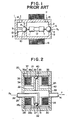
- the nozzle - flapper type valve has been common as a conventional electric - pneumatic servo valve.
- a nozzle - flapper type pneumatic servo valve has the following shortcomings.
- the reference numeral 1 denotes a main body
- 2 denotes a first chamber formed within the main body 1
- 3 denotes a second chamber which is also formed within the main body 1.
- 4 is a source pressure valve outlet which opens into the first chamber 2 and receives a source pressure P0 from outside
- 5 is a valve element which cooperates with the source pressure valve outlet 4
- the source pressure valve outlet 4 and the valve element 5 make up a source pressure valve 6.
- 7 is an armature of the source pressure valve 6, mounted on the valve element 5.
- valve 8 is a pressure relief valve outlet which communicates the first chamber 2 with the second chamber 3, while 9 is a valve element which cooperates with the pressure relief valve outlet 8, and the pressure relief valve outlet 8 -and the valve element 9 make up a pressure relief valve 10.
- 11 is an armature of the pressure relief valve 10, mounted on the valve element 9, while 12 is a gain adjustment spring which, interposed between the two armatures 7, 11, biases the valve element 5 so as to close the source pressure valve outlet 4 and at the same time biases the valve element 9 so as to open the pressure relief valve outlet 8.
- 13 is a zero adjustment spring which biases the valve element 9 so as to close the pressure relief valve outlet 8
- 14 is an opening which communicates the second chamber 3 with the atmosphere
- 15 is an output port which opens out from the first chamber 2
- 16 is an electromagnetic coil.
- the output pressure P may be controlled.
- This pneumatic servo valve can alleviate the shortcomings of the previously mentioned nozzle - flapper type pneumatic servo valve to a certain extent. However, even according to this pneumatic servo valve, there are such shortcomings as:
- a servo valve comprising a source pressure valve whose inlet end receives a source pressure, a pressure relief valve which operates independently from said source pressure valve in mechanical sense and whose outlet end is kept at a pressure which is lower than said source pressure, an output port which is connected both to an outlet end of said source pressure valve and to an inlet end of said pressure relief valve, and an electric circuit which, when an input signal has changed to the effect that an output pressure on said output port should be raised, activates said source pressure valve so as to reduce a pressure difference between said inlet and said outlet ends of said source pressure valve, and activates said pressure relief valve so as to increase a pressure difference between said inlet and said outlet ends of said pressure relief valve, and, when said input signal has changed to the effect that said output pressure on said output port should be lowered, activates said source pressure valve so as to increase said pressure difference between said inlet and said outlet ends of said source pressure valve, and activates said pressure relief valve so as to reduce said pressure difference between said inlet and said outlet ends of said source pressure valve, and activates
- the servo valve of this invention particularly since the valve elements of the source pressure valve and the pressure relief valve, or the first and the second valve elements, may be activated independently and there is no mechanical part interconnected between the two valve elements, the response of the servo valve may be made extremely fast, and, since the mechanical structure is extremely simplified and the number of component parts becomes extremely small, no subtle mechanical adjustment is required, as opposed to the conventional devices, and, further, even when the source pressure has changed there is no need to repeat the mechanical adjustment all over again.
- each of the valve seats as a bevelled opening and each of the valve elements as a globular member
- each of the electromagnetic means or the drive means as consisting of a stator core surrounding the valve seat, a coil disposed substantially inside the stator core, and a discular armatrue opposing to the corresponding stator core with a magnetic gap therebetween for driving the corresponding valve element.
- an extremely fast response may be achieved because the movable parts, i.e. the armature and the valve element, may have small masses whereas the coil may be able to exert a strong electromagnetic force to the armature through the advantageous configuration of the stator core and the armature.
- Fig. 2 is a sectional view showing a mechanical structural portion of a servo valve 20 according to a preferred embodiment of this invention.
- a casing 21 Within a casing 21 are defined a first chamber 23 and a second chamber 24 which are mutually separated from each other by a partition wall 22.
- 25 is a tubular source pressure passage member and an end of this source pressure passage member 25 projects outside of the casing 21, while the other end projects into the first chamber 23.
- the interior of the source pressure passage member 25 defines a source pressure passage 26, which is connected to a source pressure supply source (not shown in the drawing) which supplies a source pressure P0.
- a valve seat 27 consisting of a bevelled opening is formed at the first chamber 23 end of the source pressure passage 26.
- the source pressure valve 32 thus comprises the source pressure passage 26, the valve seat 27, the stator core 28, the coil 29, the armature 30, and the valve element 31.
- the first chamber 23 and the second chamber 24 are mutually communicated by way of a pressure relief passage 34 provided in a tubular portion integrally formed with the partition wall 24, and a valve seat 35 consisting of a bevelled opening is formed at the tip of this pressure relief passage 34.
- a substantially double tubular stator core 36 consisting of magnetic material
- a coil 37 is accommodated between an outer tubular portion 36a and an inner tubular portion 36b of this stator core 36.
- a disk shaped armature 38 is loosely interposed between the stator core 36 and the casing 21 so as to complete a magnetic circuit in cooperation with the stator core 36, and a globular valve element 39 is accommodated between this magnetic pole body and the valve seat 35.
- the pressure relief valve 40 comprises the gressure relief passage 34, the valve seat 35, the stator core 36, the coil 37, the armature 38, and the valve element 39.
- the casing 21 is provided with an output port 41 which communicates with the first chamber 23, and with an opening 42 which communicates the second chamber 24 with the atmosphere.
- Fig. 3 is a block diagram showing the servo valve 20 inclusive of its control euireuit.
- 43 is an electric circuit which has an amplifier 44 for amplifying an input electric signal Si and a DC power source 45 for outputting a fixed bias voltage Vb.
- an output voltage v of the amplifier 44 is directly supplied to the coil 37 of the pressure relief valve 40 for driving it, while a voltage (Vb - v) obtained by subtracting the output voltage v of the amplifier 44 from the bias voltage Vb is supplied to the coil 29 of the source pressure valve 32 for driving it.
- this servo valve 20 since in this servo valve 20 the value of the output pressure P is determined substantially only by the source pressure valve 32 when the output pressure P rises and the value. of the output pressure P is likewise determined substantially only by the pressure relief valve 40 when the output pressure P decreases, this servo valve 20 may be expressed by the block diagram given in Fig. 4 in equivalent sense.
- S is a switch which automatically switches to the side of the source pressure valve 32 when the output pressure P rises and to the side of the pressure relief valve 40 when the output pressure P drops down.
- the input signal Si and the output pressure P have a certain relationship determined by Eqs. (5) and (6).
- the output pressure P on the output port 41 may be controlled with the input signal Si.
- this servo valve 20 In the naked properties of this servo valve 20, there is some hysteresis between the time when the output pressure P is rising and the time when the output pressure P is dropping. This is caused by the hysteresis properties of the stator cores 28 and 36, and the armatures 30 and 38, but such a hysteresis may be removed of its effect by performing a feedback control as will be described later.
- Eq. (16) may be expressed in a block diagram as shown in Fig. 6, where K' is expressed by separating it into KI and K2.
- the outlet end of the pressure relief valve 40 was connected to the atmosphere, but by connecting this outlet end of the pressure relief valve 40 to a vacuum pump it becomes possible to control the output pressure P from positive pressure to negative pressure.
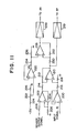
- Fig. 8 an example of a concrete arrangement of the electric circuit 43 shown in Fig. 3 is shown for the aid of the following description.
- 100 is an operational amplifier for amplifying an input signal Si, and its inverting input is directly connected to its output for negative feedback, while its non-inverting input receives the input signal Si.
- the output signal v of the operational amplifier 100 is power-amplified by a differential power amplifier 101, and then supplied to the coil 37 of the pressure relief valve 40 for driving it.
- 102 is an operational amplifier for obtaining a bias voltage Vb and its inverting input is directly connected to its output for negative feedback, while its non-inverting input is connected to a slider tap of a potentiometer 104.
- One of the terminals of the potentiometer 104 is connected to a + 15V line by way of a resistor 106, while the other of the terminals is grounded via a resistor 108.
- the value of the bias voltage Vb obtained on the output of the operational amplifier 102 may be adjusted by moving the slider tap of the potentiometer 104.
- the 110 is an operational amplifier which makes up a subtraction circuit along with resistors 112, 114, 116, and 118.
- the inverting input of the operational amplifier 110 is connected to its output by way of the resistor 114 for negative feedback, and is also connected to the output of the operational amplifier 100 by way of the resistor 112.
- the non-inverting input of the operational amplifier 110 is connected to the output of the operational amplifier 102 by way of the resistor 116 and is grounded via the resistor 118.
- This difference signal vl is power-amplified by a differential power amplifier 120 and then supplied to the coil 29 of the pressure source valve 32 for driving it.
- Fig. 9 is a block diagram illustrating an embodiment of the automatic control system which includes an embodiment of the servo valve of this invention.
- the servo valve comprises an electric circuit 50 which will be described in detail later, and a source pressure valve 32 and a pressure relief valve 40 both of which are identical in structure to those shown in Fig. 2.
- 51 is a converting unit which detects the output pressure P and converts it into a main feedback signal b which is an electric signal.
- 53 is a comparing unit which compares an input signal Si which represents a reference value and the main feedback signal b and produces a control deviation signal c which represents their difference or control deviation.
- the electric circuit 50 has compensation circuits 54 and 55 and a DC power source 56.
- the compensation circuits 54 and 55 perform a compensation action which will be described in the following, and both receive the control deviation signal c.
- a voltage obtained by subtracting the output voltage of the compensation circuit 54 from the bias voltage Vb supplied from the DC power source 56 is supplied to the source pressure valve 32 for driving it, while the output voltage of the compensation circuit 55 is directly supplied to the pressure relief valve 40 for driving it.
- Fig. 10 is a block diagram of the servo valve system of Fig. 9 in mathematical expression.
- the compensation circuits 54 and 55 are integration compensation elements or in other words in Fig. 10: and an integration compensation is to be performed, it becomes possible to reduce the steady state deviation to zero and to improve the control accuracy or precision. And even when there is some change in the source pressure P0, it becomes possible to eliminate its effect, but oscillation tends to develop.
- the control precision may be somewhat improved, and even when there is some change in the source pressure P0, its effect may be eliminated, and the system may be stabilized.
- the control precision may be raised to an extremely high level, and even when there is some change in the source pressure P0, its effect may be removed and the system may be stabilized, and furthermore the responsiveness may be improved even further.
- Fig. 11 shows an example of a concrete arrangement of the electric circuit 50, the amplifier 52, the comparison unit 53, and the converting unit 51 of Fig. 9. This example applies to the above described simple gain compensation.
- 200 is an operational amplifier which makes up an amplifier 52 (Fig. 9), and its non-inverting input receives an input signal Si which determines the reference value while its inverting input is directly connected to its output for negative feedback.
- 202 is an operational amplifier which makes up the converting unit 51 (Fig. 9) along with a pressure sensor (not shown) which detects the output pressure P.
- the inverting input of the operational amplifier 202 is connected to its output by way of a resistor 204 for negative feedback and is additionally grounded by way of a resistor 206.
- the output signal of the pressure sensor is applied to the non-inverting input of the operational amplifier 202 by way of a resistor 208.
- 210 is an operational amplifier which makes up a subtraction circuit which functions as the comparison unit 53.
- the inverting input of this operational amplifier 210 is connected to its output by way of a resistor 212 and also to the output of the operational amplifier 202 by way of a resistor 214.
- the non-inverting input of the operational amplifier 210 is connected to the output of the operational amplifier 200 by way of a resistor 216, and is additionally grounded by way of a resistor 218. From the operational amplifier 210 is outputted a difference signal between the output signals of the operational amplifiers 200 and 202, respectively, or in other words a control deviation signal.
- This control deviation signal after being power-amplified by the differential power amplifier 219, is supplied to the coil 37 of the pressure relief valve 40 for driving it.
- the 220 is an operational amplifier for obtaining the bias voltage Vb, and its inverting input is directly connected to its output for negative feedback, while its non-inverting input is connected to a slider tap of a potentiometer 222.
- One of the terminals of the potentiometer 222 is connected to a + 15V line by way of a resistor 224, and the other of the terminals is grounded by way of a resistor 226.
- the value of the bias voltage Vb obtained on the output of the operational amplifier 220 may be adjusted by moving the slider tap of the potentiometer 222.
- the 228 is an operational amplifier which makes up a subtraction circuit along with resistors 230, 232, 234, and 236.
- the inverting input of the operational amplifier 228 is connected to its output by way of the resistor 232 for negative feedback, and is also connected to the output of the operational amplifier 210 by way of the resistor 230.
- the non-inverting input of the operational amplifier 228 is connected to the output of the operational amplifier 220 by way of the resistor 234 and is also grounded by way of the resistor 236.
- On the output of the operational amplifier 228 is obtained a difference signal between the bias voltage Vb and the output signal of the operational amplifier 210. This difference signal is power-amplified by a differential power amplifier 238 and is supplied to the coil 29 of the pressure source valve 32.
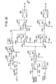
- Fig. 12 shows another example of a concrete arrangement of the electric circuit 50, the amplifier 52, the comparison unit 53, and the converting unit 51 of Fig. 9. This example applies to the case when the above mentioned phase delay compensation is to be performed.
- 300 is an operational amplifier which makes up the amplifier 52 (Fig. 9), and its non-inverting input receives the input signal Si which determines a reference value, while its inverting input is connected directly to its output for negative feedback.
- 302 is an operational amplifier which makes up the converting unit 51 (Fig. 9) along with a pressure sensor (not shown) which detects the output pressure P.
- the inverting input of the operational amplifier 302 is connected to its output by way of a resistor 304 for negative feedback, and is also grounded by way of a resistor 306.
- the output signal of the pressure sensor is applied to the non-inverting input of the operational amplifier 302 by way of a resistor 308.
- the 310 is an operational amplifier which makes up a subtraction circuit which functions as the comparison unit 53.
- the inverting input of this operational amplifier 310 is connected to its output by way of a resistor 312 and is also connected to the output of the operational amplifier 302 by way of a resistor 314.
- the non-inverting input of the operational amplifier 310 is connected to the output of the operational amplifier 300 by way of a resistor 316, and is also grounded by way of a resistor 318. From the operational amplifier 310 is produced a difference signal between the output signals of the operational amplifiers 300 and 302, respectively, or in other words a control deviation signal.
- 320 is an operational amplifier which, along with a capacitor 321 for integration and others, makes up a first-order lag element serving as the compensation circuit 55 on the side of the pressure relief valve 40.
- the non-inverting input of this operational amplifier 320 is grounded by way of a resistor 324 and its inverting input and output are mutually connected by way of a capacitor 321 and a series connection of a resistor 326 and a variable resistor 328.
- the control deviation signal produced from the operational amplifier 310 is supplied to the inverting input of the operational amplifier 320 by way of a resistor 330.
- T2 of the transfer function H2 1/(1+T2s) of this compensation circuit may be adjusted by the variable resistor 328.
- the operational amplifier 332 makes up an inverting amplifier circuit along with the resistor 334, 336, and 338.
- the non-inverting input of the operational amplifier 332 is grounded by way of the resistor 338, while its inverting input is connected to its output by way of the resistor 334 and is also connected to the output of the operational amplifier 320 by way of the resistor 336.
- the output signal of the operational amplifier 320 is both polarity inverted and voltage amplified by this inverting amplifier circuit, and then power-amplified by a differential power amplifier 340 and is supplied to the coil 37 of the pressure relief valve 40 for driving it.
- T1 of the transfer function H1 1/(1+T1s) of this compensation circuit may be adjusted by the variable resistor 350.
- 354, 356, and 358 are operational amplifiers for obtaining the bias voltage Vb.
- the non-inverting input of the operational amplifier 354 is grounded by a resistor 360, and its inverting input is connected to its output by way of a resistor 362 for negative feedback.
- the inverting input of the operational amplifier 354 is connected to a slider tap of a potentiometer 366 by way of a resistor 364.
- One of the terminals of the potentiometer 366 is connected to a - 15V line by way of a resistor 368 and the other of the terminals of the potentiometer 366 is grounded by way of a resistor 370.
- the non-inverting input of the operational amplifier 356 is grounded by way of a resistor 372 and its inverting input is connected to its output and the output of the operational amplifier 354 by way of resistors 374 and 376, respectively.
- the inverting input of the operational amplifier 358 is connected to its output, and its non-inverting input is connected to the output of the operational amplifier 356.
- the bias voltage Vb is obtained on the output of the operational amplifier 358 and its value may be adjusted by moving the slider tap of the potentiometer 366.
- the operational amplifier 372 makes up a subtraction circuit along with resistors 374, 376, 378, and 380.
- the inverting input of the operational amplifier 372 is connected to its output by way of a resistor 376 for negative feedback and is also connected to the output of the operational amplifier 358 by way of the resistor 374.
- the non-inverting input of the operational amplifier 372 is connected to the output of the operational amplifier 342 by way of the resistor 378 and is grounded via the resistor 380.
- On the output of the operational amplifier 372 is produced a difference signal between the output signal of the operational amplifier 342 and the bias voltage Vb. This difference signal is power-amplified by the differential power amplifer 382 and then supplied to the coil 29 of the pressure source valve 32 for driving it.
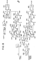
- Fig. 13 shows another example of a concrete arrangement of the electric circuit 50, the amplifier 52, the comparison unit 53, and the converting unit 51 of Fig. 9. This example applies to the case when the above mentioned differentiation - integration compensation is to be performed.
- 400 is an operational amplifier for the amplifier 52 (Fig. 9), and its non-inverting input receives an input signal Si which determines a reference value while its inverting input is directly connected to its output for negative feedback.
- 402 and 404 are operational amplifiers which make up the converting unit 51 (Fig. 9) along with a pressure sensor (not shown) which detects the output pressure P.
- the inverting input of the operational amplifier 402 is connected to its output by way of a variable resistor 406 for negative feedback, and is grounded via a resistor 408.
- the output signal of the pressure sensor is supplied to the non-inverting input of the operational amplifier 402 by way of a resistor 410.
- the inverting input of the operational amplifier 404 is directly connected to its output, while its non-inverting input is directly connected to the output of the operational amplifier 402.
- the 412 is an operational amplifier which makes up a subtraction circuit which functions as the comparison unit 53.
- the inverting input of this operational amplifier 412 is connected to its output by way of a resistor 414 and is also connected to the output of the operational amplifier 400 by way of a resistor 416.
- a non-inverting input of the operational amplifier 412 is connected to the output of the operational amplifier 404 by way of a resistor 418, and is grounded via a resistor 420. From the operational amplifier 412 is produced a difference signal between the output signals of the operational amplifiers 400 and 404 or in other words a control deviation signal.
- the operational amplifier 424, 426, 427, 428, and 450 are operational amplifiers which make up the compensation circuit 55 on the side of the pressure relief valve 40.
- the operational amplifier 424 makes up an integration circuit, and its inverting input is connected to its output by way of a capacitor 430 for integration and is also connected to the output of the operational amplifier 412 by way of a resistor 432 while its non-inverting input is directly grounded.
- the inverting input of the operational amplifier 426 is connected to its output and the output of the operational amplifier 424 by way of resistors 434 and 436, respectively, while the non-inverting input is grounded via a resistor 435.
- the inverting input of the operational amplifier 428 is connected to its output by way of a variable resistor 438, and is grounded via a resistor 440 while its non-inverting input is connected to the output of the operational amplifier 412 by way of a resistor 441.
- the operational amplifier 427 makes up an addition circuit for adding up the output signals of the operational amplifiers 426 and 428, and its inverting input is connected to its output by way of a resistor 442 while its non-inverting input is grounded via a resistor 444.
- the output signals of the operational amplifiers 426 and 428 are applied to the inverting input of the operational amplifier 427 by way of resistors 446 and 448, respectively.
- the first term of this equation is accomplished by the circuit of the operational amplifiers 424 and 426 and the second term is accomplished by the circuit of the operational amplifier 428, while the addition of the first and the second terms is accomplished by the circuit of the operational amplifier 427.
- the operational amplifier 450 makes up an inverting amplifier circuit, and its non-inverting input is grounded by a resistor 452 while its inverting input is connected to its output and the output of the operational amplifier 427 by way of resistors 454 and 456, respectively.
- the output signal of the operational amplifier 450 is power-amplified by a differential power amplifier 458 and then supplied to the coils 37 of the pressure relief valve 40 for driving it.
- the operational amplifier 460, 462, 464, 466, and 468 are operational amplifiers which make up the compensation circuit 54 on the side of the pressure source valve 32.
- the operational amplifier 460 makes up an integration circuit, and its inverting input is connected to its output by way of a capacitor 470 for integration, and is also connected to the output of the operational amplifier 412 by way of a resistor 472, while its non-inverting input is directly grounded.
- the inverting input of the operational amplifier 462 is connected to its output and the output of the operational amplifier 460, by way of resistors 474 and 476, respectively, while its non-inverting input is grounded via a resistor 478.
- the inverting input of the operational amplifier 466 is connected to its output by way of a variable resistor 480, and is grounded via a resistor 482, while its non-inverting input is connected to the output of the operational amplifier 412 by way of a resistor 484.
- the operational amplifier 464 makes up an addition circuit for adding up the output signals of the operational amplifiers 462 and 466, and its inverting input is connected to its output by way of a resistor 486, while its non-inverting input is grounded via a resistor 488.
- the output signals of the operational amplifiers 462 and 466 are applied to the inverting input of the operational amplifier 464 by way of resistors 490 and 492, respectively.
- the first term of this equation is accomplished by the circuit of the operational amplifiers 460 and 462, and the second term is accomplished by the circuit of the operational amplifier 466, while the addition of the first and the second terms is accomplished by the circuit of the operational amplifier 464.
- the operational amplifier 468 makes up an inverting amplifier circuit and its non-inverting input is grounded via a resistor 494, while its inverting input is connected to its output and the output of the operational amplifier 464 by way of resistors 496 and 498, respectively.
- the inverting input of the operational amplifier 504 is directly connected to its output, while its non-inverting input is connected to a connection between the resistors 500 and 502.
- the bias voltage Vb is obtained on the output of the operational amplifier 504.
- the operational amplifier 506 makes up a subtraction circuit along with resistors 508, 510, 512, and 514.
- the inverting input of the operational amplifier 506 is connected to its output by way of the resistor 514 for negative feedback, and is also connected to the output of the operational amplifier 468 by way of the resistor 512.
- the non-inverting input of the operational amplifier 506 is connected to the output of the operational amplifier 504 by way of the resistor 508, and is grounded via the resistor 510.
- On the output of the operational amplifier 506 is obtained a difference signal between the output signal of the operational amplifier 468 and the bias voltage Vb. This difference signal is power-amplified by the differential power amplifier 516 and is then supplied to the coil 29 of the pressure source valve 32 for driving it.
Applications Claiming Priority (2)
| Application Number | Priority Date | Filing Date | Title |
|---|---|---|---|
| JP96926/83 | 1983-06-02 | ||
| JP58096926A JPS6084404A (ja) | 1983-06-02 | 1983-06-02 | サーボ弁 |
Publications (2)
| Publication Number | Publication Date |
|---|---|
| EP0127875A2 true EP0127875A2 (de) | 1984-12-12 |
| EP0127875A3 EP0127875A3 (de) | 1985-08-28 |
Family
ID=14177950
Family Applications (1)
| Application Number | Title | Priority Date | Filing Date |
|---|---|---|---|
| EP84106139A Withdrawn EP0127875A3 (de) | 1983-06-02 | 1984-05-29 | Servoventil |
Country Status (3)
| Country | Link |
|---|---|
| US (1) | US4580598A (de) |
| EP (1) | EP0127875A3 (de) |
| JP (1) | JPS6084404A (de) |
Cited By (3)
| Publication number | Priority date | Publication date | Assignee | Title |
|---|---|---|---|---|
| EP0294072A2 (de) * | 1987-06-01 | 1988-12-07 | Parker Hannifin Corporation | Vorrichtung zum Steuern oder Regeln des Durchflusses eines Druckgases zwischen zwei Druckgasvorrichtungen |
| WO1991000562A1 (en) * | 1989-06-29 | 1991-01-10 | Allied-Signal Inc. | Doser system for regulating pressure in a control chamber of a test stand |
| BE1023112B1 (fr) * | 2015-05-19 | 2016-11-23 | Techspace Aero S.A. | Vanne electromagnetique cryogenique autoclave pour lanceur spatial |
Families Citing this family (20)
| Publication number | Priority date | Publication date | Assignee | Title |
|---|---|---|---|---|
| JPH0641795B2 (ja) * | 1984-06-15 | 1994-06-01 | 株式会社ブリヂストン | 電磁式流量制御弁 |
| JPS616474A (ja) * | 1984-06-21 | 1986-01-13 | Bridgestone Corp | 電磁式流量制御弁 |
| DE3501708A1 (de) * | 1985-01-19 | 1986-07-24 | Wabco Westinghouse Fahrzeugbremsen GmbH, 3000 Hannover | Elektromagnetisch betaetigbares mehrwegeventil |
| JPS62106107A (ja) * | 1985-11-01 | 1987-05-16 | Bridgestone Corp | 多チヤンネルサ−ボ弁 |
| JPS62270805A (ja) * | 1986-05-16 | 1987-11-25 | Bridgestone Corp | サ−ボ・バルブ |
| US5018431A (en) * | 1988-12-09 | 1991-05-28 | Quadrastat Corporation | Apparatus for positioning a work implement |
| US5197675A (en) * | 1991-02-11 | 1993-03-30 | Siemens Automotive L.P. | Fuel rail having rolling ball fuel injectors |
| GB9302096D0 (en) * | 1993-02-03 | 1993-03-24 | Century Associates Limited | Pipeline pig control apparatus |
| US5421521A (en) * | 1993-12-23 | 1995-06-06 | Caterpillar Inc. | Fuel injection nozzle having a force-balanced check |
| GB2289313B (en) * | 1994-05-13 | 1998-09-30 | Caterpillar Inc | Fluid injector system |
| US6575137B2 (en) | 1994-07-29 | 2003-06-10 | Caterpillar Inc | Piston and barrel assembly with stepped top and hydraulically-actuated fuel injector utilizing same |
| US5826562A (en) * | 1994-07-29 | 1998-10-27 | Caterpillar Inc. | Piston and barrell assembly with stepped top and hydraulically-actuated fuel injector utilizing same |
| US5463996A (en) * | 1994-07-29 | 1995-11-07 | Caterpillar Inc. | Hydraulically-actuated fluid injector having pre-injection pressurizable fluid storage chamber and direct-operated check |
| US5697342A (en) * | 1994-07-29 | 1997-12-16 | Caterpillar Inc. | Hydraulically-actuated fuel injector with direct control needle valve |
| US5687693A (en) * | 1994-07-29 | 1997-11-18 | Caterpillar Inc. | Hydraulically-actuated fuel injector with direct control needle valve |
| US6082332A (en) * | 1994-07-29 | 2000-07-04 | Caterpillar Inc. | Hydraulically-actuated fuel injector with direct control needle valve |
| DE4445686C2 (de) * | 1994-12-21 | 1999-06-24 | Fraunhofer Ges Forschung | Mikroventilanordnung, insbesondere für pneumatische Steuerungen |
| US5813226A (en) * | 1997-09-15 | 1998-09-29 | Caterpillar Inc. | Control scheme for pressure relief |
| WO2000034646A1 (en) | 1998-12-11 | 2000-06-15 | Caterpillar Inc. | Piston and barrel assembly with stepped top and hydraulically-actuated fuel injector utilizing same |
| KR101887360B1 (ko) * | 2013-10-31 | 2018-08-10 | 가부시키가이샤 후지킨 | 압력식 유량 제어 장치 |
Citations (5)
| Publication number | Priority date | Publication date | Assignee | Title |
|---|---|---|---|---|
| US2910079A (en) * | 1955-04-18 | 1959-10-27 | Phillips Petroleum Co | Process and apparatus for controlling liquid pressure surge in a line |
| GB877150A (en) * | 1959-02-23 | 1961-09-13 | British Transp Commission | Improvements in or relating to electro-magnetically operated valves for controlling the flow of compressed air |
| DE1218834B (de) * | 1958-12-08 | 1966-06-08 | Rech Etudes Prod | Elektromagnetisch betaetigtes Ventil mit einem verschiebbaren Ventilsitz |
| GB1450402A (en) * | 1972-09-22 | 1976-09-22 | Bosch Gmbh Robert | Fluid control valves |
| JPS58161821A (ja) * | 1982-03-20 | 1983-09-26 | Roudoushiyou Sangyo Anzen Kenkyusho | 電気−空気圧変換装置 |
Family Cites Families (4)
| Publication number | Priority date | Publication date | Assignee | Title |
|---|---|---|---|---|
| US3225782A (en) * | 1963-04-05 | 1965-12-28 | Warren W Begley | Fluid control system |
| US3565111A (en) * | 1969-02-20 | 1971-02-23 | Swan A Pearson | Solenoid-actuated pilot valve |
| US3861644A (en) * | 1973-10-09 | 1975-01-21 | Gen Motors Corp | Solenoid valve |
| DE2928005A1 (de) * | 1978-07-18 | 1980-02-14 | Diesel Kiki Co | Ferngesteuerte proportionalregelungs- richtungsumschalt-regelventilvorrichtung |
-
1983
- 1983-06-02 JP JP58096926A patent/JPS6084404A/ja active Granted
-
1984
- 1984-05-22 US US06/613,060 patent/US4580598A/en not_active Expired - Fee Related
- 1984-05-29 EP EP84106139A patent/EP0127875A3/de not_active Withdrawn
Patent Citations (5)
| Publication number | Priority date | Publication date | Assignee | Title |
|---|---|---|---|---|
| US2910079A (en) * | 1955-04-18 | 1959-10-27 | Phillips Petroleum Co | Process and apparatus for controlling liquid pressure surge in a line |
| DE1218834B (de) * | 1958-12-08 | 1966-06-08 | Rech Etudes Prod | Elektromagnetisch betaetigtes Ventil mit einem verschiebbaren Ventilsitz |
| GB877150A (en) * | 1959-02-23 | 1961-09-13 | British Transp Commission | Improvements in or relating to electro-magnetically operated valves for controlling the flow of compressed air |
| GB1450402A (en) * | 1972-09-22 | 1976-09-22 | Bosch Gmbh Robert | Fluid control valves |
| JPS58161821A (ja) * | 1982-03-20 | 1983-09-26 | Roudoushiyou Sangyo Anzen Kenkyusho | 電気−空気圧変換装置 |
Non-Patent Citations (1)
| Title |
|---|
| PATENT ABSTRACTS OF JAPAN, vol. 7, no. 286, 21st December 1983, page 167 P 244 (P-244) (1431); & JP-A-58 161 821 (ROUDOUSHIYOU SANGYO) 26-09-1983 * |
Cited By (6)
| Publication number | Priority date | Publication date | Assignee | Title |
|---|---|---|---|---|
| EP0294072A2 (de) * | 1987-06-01 | 1988-12-07 | Parker Hannifin Corporation | Vorrichtung zum Steuern oder Regeln des Durchflusses eines Druckgases zwischen zwei Druckgasvorrichtungen |
| EP0294072A3 (en) * | 1987-06-01 | 1990-03-07 | Parker Hannifin Corporation | Electrically controlled variable pressure pneumatic circuit |
| WO1991000562A1 (en) * | 1989-06-29 | 1991-01-10 | Allied-Signal Inc. | Doser system for regulating pressure in a control chamber of a test stand |
| BE1023112B1 (fr) * | 2015-05-19 | 2016-11-23 | Techspace Aero S.A. | Vanne electromagnetique cryogenique autoclave pour lanceur spatial |
| EP3096053A1 (de) * | 2015-05-19 | 2016-11-23 | Techspace Aero S.A. | Kryogenes elektromagnetisches autoklavenventil für trägerrakete |
| US9964228B2 (en) | 2015-05-19 | 2018-05-08 | Safran Aero Boosters Sa | Autoclave cryogenic electromagnetic valve for a space launch vehicle |
Also Published As
| Publication number | Publication date |
|---|---|
| EP0127875A3 (de) | 1985-08-28 |
| US4580598A (en) | 1986-04-08 |
| JPS6084404A (ja) | 1985-05-13 |
| JPS6333001B2 (de) | 1988-07-04 |
Similar Documents
| Publication | Publication Date | Title |
|---|---|---|
| EP0127875A2 (de) | Servoventil | |
| US5509439A (en) | Electromagnetically controlled operating device in particular for valves and electrohydraulic applications | |
| EP0919754A3 (de) | Elektromagnetisches Proportionalventil mit Ankerdämpfung | |
| JPH05126106A (ja) | 可変フオースモータを備えた電磁ソレノイド弁 | |
| US4362182A (en) | Nozzle force feedback for pilot stage flapper | |
| US4553732A (en) | Solenoid controlled flow valve | |
| JPS60157576A (ja) | 電気制御圧力変換弁 | |
| US3598138A (en) | Pressure controller | |
| US3811465A (en) | Electric-fluidic direct proportion converter | |
| US4598729A (en) | Negative pressure control valve | |
| CA2608686C (en) | Fluid regulation control | |
| US3065735A (en) | Servoactuator | |
| GB2186349A (en) | Proportional solenoid valve | |
| EP0503357B1 (de) | Durchflussregelventil | |
| JPH0219845Y2 (de) | ||
| US5174339A (en) | Fluid flow control valve | |
| JPH11510124A (ja) | 電磁作動装置 | |
| US3587617A (en) | Fluid control apparatus | |
| GB2158971A (en) | Digital servovalve structure and method | |
| US2985182A (en) | Electro-pneumatic converters | |
| EP0409664B1 (de) | Druckregler und Ventilbetätigungsvorrichtung | |
| JP2553345B2 (ja) | 圧力制御弁 | |
| JPH0357356B2 (de) | ||
| JPH0426897Y2 (de) | ||
| US4850384A (en) | Electric vacuum regulator |
Legal Events
| Date | Code | Title | Description |
|---|---|---|---|
| PUAI | Public reference made under article 153(3) epc to a published international application that has entered the european phase |
Free format text: ORIGINAL CODE: 0009012 |
|
| AK | Designated contracting states |
Designated state(s): CH DE FR GB IT LI NL |
|
| PUAL | Search report despatched |
Free format text: ORIGINAL CODE: 0009013 |
|
| AK | Designated contracting states |
Designated state(s): CH DE FR GB IT LI NL |
|
| 17P | Request for examination filed |
Effective date: 19851121 |
|
| 17Q | First examination report despatched |
Effective date: 19870109 |
|
| STAA | Information on the status of an ep patent application or granted ep patent |
Free format text: STATUS: THE APPLICATION IS DEEMED TO BE WITHDRAWN |
|
| 18D | Application deemed to be withdrawn |
Effective date: 19870120 |