EP0127360A2 - Waschmaschinen - Google Patents
Waschmaschinen Download PDFInfo
- Publication number
- EP0127360A2 EP0127360A2 EP84303190A EP84303190A EP0127360A2 EP 0127360 A2 EP0127360 A2 EP 0127360A2 EP 84303190 A EP84303190 A EP 84303190A EP 84303190 A EP84303190 A EP 84303190A EP 0127360 A2 EP0127360 A2 EP 0127360A2
- Authority
- EP
- European Patent Office
- Prior art keywords
- drum
- tub
- washing machine
- portions
- water
- Prior art date
- Legal status (The legal status is an assumption and is not a legal conclusion. Google has not performed a legal analysis and makes no representation as to the accuracy of the status listed.)
- Withdrawn
Links
- 238000005406 washing Methods 0.000 title claims abstract description 31
- XLYOFNOQVPJJNP-UHFFFAOYSA-N water Substances O XLYOFNOQVPJJNP-UHFFFAOYSA-N 0.000 claims abstract description 28
- 229920003023 plastic Polymers 0.000 claims abstract description 7
- 239000004033 plastic Substances 0.000 claims abstract description 7
- 239000011521 glass Substances 0.000 claims abstract description 5
- 239000000463 material Substances 0.000 claims abstract description 5
- 238000004519 manufacturing process Methods 0.000 claims description 6
- 230000003068 static effect Effects 0.000 claims description 5
- 238000003780 insertion Methods 0.000 claims description 2
- 230000037431 insertion Effects 0.000 claims description 2
- 239000003599 detergent Substances 0.000 description 3
- 238000009826 distribution Methods 0.000 description 2
- 239000013049 sediment Substances 0.000 description 2
- 230000003319 supportive effect Effects 0.000 description 2
- 208000010392 Bone Fractures Diseases 0.000 description 1
- 206010017076 Fracture Diseases 0.000 description 1
- 238000010276 construction Methods 0.000 description 1
- 238000005304 joining Methods 0.000 description 1
- 239000007788 liquid Substances 0.000 description 1
- QSHDDOUJBYECFT-UHFFFAOYSA-N mercury Chemical compound [Hg] QSHDDOUJBYECFT-UHFFFAOYSA-N 0.000 description 1
- 229910052753 mercury Inorganic materials 0.000 description 1
- 239000000843 powder Substances 0.000 description 1
- 238000010079 rubber tapping Methods 0.000 description 1
- 238000009987 spinning Methods 0.000 description 1
- 229910001220 stainless steel Inorganic materials 0.000 description 1
- 239000010935 stainless steel Substances 0.000 description 1
- 238000003466 welding Methods 0.000 description 1
Images
Classifications
-
- D—TEXTILES; PAPER
- D06—TREATMENT OF TEXTILES OR THE LIKE; LAUNDERING; FLEXIBLE MATERIALS NOT OTHERWISE PROVIDED FOR
- D06F—LAUNDERING, DRYING, IRONING, PRESSING OR FOLDING TEXTILE ARTICLES
- D06F37/00—Details specific to washing machines covered by groups D06F21/00 - D06F25/00
- D06F37/26—Casings; Tubs
- D06F37/261—Tubs made by a specially selected manufacturing process or characterised by their assembly from elements
- D06F37/262—Tubs made by a specially selected manufacturing process or characterised by their assembly from elements made of plastic material, e.g. by injection moulding
-
- D—TEXTILES; PAPER
- D06—TREATMENT OF TEXTILES OR THE LIKE; LAUNDERING; FLEXIBLE MATERIALS NOT OTHERWISE PROVIDED FOR
- D06F—LAUNDERING, DRYING, IRONING, PRESSING OR FOLDING TEXTILE ARTICLES
- D06F37/00—Details specific to washing machines covered by groups D06F21/00 - D06F25/00
- D06F37/02—Rotary receptacles, e.g. drums
- D06F37/04—Rotary receptacles, e.g. drums adapted for rotation or oscillation about a horizontal or inclined axis
-
- D—TEXTILES; PAPER
- D06—TREATMENT OF TEXTILES OR THE LIKE; LAUNDERING; FLEXIBLE MATERIALS NOT OTHERWISE PROVIDED FOR
- D06F—LAUNDERING, DRYING, IRONING, PRESSING OR FOLDING TEXTILE ARTICLES
- D06F37/00—Details specific to washing machines covered by groups D06F21/00 - D06F25/00
- D06F37/26—Casings; Tubs
- D06F37/261—Tubs made by a specially selected manufacturing process or characterised by their assembly from elements
- D06F37/263—Tubs made by a specially selected manufacturing process or characterised by their assembly from elements assembled from at least two elements connected to each other; Connecting or sealing means therefor
-
- D—TEXTILES; PAPER
- D06—TREATMENT OF TEXTILES OR THE LIKE; LAUNDERING; FLEXIBLE MATERIALS NOT OTHERWISE PROVIDED FOR
- D06F—LAUNDERING, DRYING, IRONING, PRESSING OR FOLDING TEXTILE ARTICLES
- D06F37/00—Details specific to washing machines covered by groups D06F21/00 - D06F25/00
- D06F37/26—Casings; Tubs
- D06F37/267—Tubs specially adapted for mounting thereto components or devices not provided for in preceding subgroups
- D06F37/269—Tubs specially adapted for mounting thereto components or devices not provided for in preceding subgroups for the bearing of the rotary receptacle
-
- D—TEXTILES; PAPER
- D06—TREATMENT OF TEXTILES OR THE LIKE; LAUNDERING; FLEXIBLE MATERIALS NOT OTHERWISE PROVIDED FOR
- D06F—LAUNDERING, DRYING, IRONING, PRESSING OR FOLDING TEXTILE ARTICLES
- D06F39/00—Details of washing machines not specific to a single type of machines covered by groups D06F9/00 - D06F27/00
- D06F39/08—Liquid supply or discharge arrangements
- D06F39/087—Water level measuring or regulating devices
Definitions
- This invention relates to washing machines.
- Washing machines are generally provided with an inner drum having an opening so that clothes to be washed may be placed thereinto.
- the drum generally has a number of holes provided in the surface thereof to allow water to enter the drum, or to drain therefrom, during certain stages of the wash programme.
- a washing machine including a drum for accommodating clothes to be washed, apertures being provided in the surface of the drum to permit water to flow into, and out of, the drum, characterised in that said drum is formed from a first and a second portion, adjoining circumferential edges of each of said portions being shaped to form co-operating flange members to be joined together during manufacture of the machine, thereby causing said portions to be joined, said flange members being shaped so as to define said apertures when said portions are so joined.
- the flange members are each shaped into an undulating configuration.
- a washing machine as set forth in one of the two preceding paragraphs, including a static tub within which said drum is housed for rotation, said tub being provided with leg portions so as to render the tub substantially free-standing and self-supportive.
- a rear portion of the tub is preferably blow-moulded from a plastics material, the leg portions being integrally moulded therewith and the rear wall of the tub is preferably shaped, such as with a number of radial ridge members, so as to strengthen the plastics portion thereof.
- the rear portion of the tub is also preferably provided with one or more weights mounted thereon, so as to aid in maintaining the tub in a static condition, whilst the inner drum is rotating, during operation of the washing machine.
- the washing machine preferably includes a sump tank assembly comprising a sump tank for collecting water from said drum, the tank acting as a water filter, and including pressure sensing and switching means for sensing the level of water within the tub and for causing the washing machine to implement a subsequent operation in a set wash program when the level reaches a predetermined height.
- the washing machine is also preferably provided with a one-piece glass door having a coloured screen on the inside surface thereof, a central portion of the surface being left transparent, the portion coinciding with an opening to the drum for insertion of clothes thereinto.
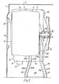
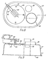
- a housing for a washing machine includes a front panel 1 and a top panel 2. There is provided, within the housing, a drum 3 formed of two half portions, 4 and 5, portion 4 having a circular opening 6, through which clothes to be washed can be inserted into the drum 3. Portions 4 and 5 are joined together by alternate portions of an undulating flange, one such portion being shown at 7, spaced around the circumference of the drum 3, forming apertures (not shown) therebetween. This feature is described in greater detail hereinafter.
- the drum 3 is contained within a tub 8, which also consists of two portions 9 and 10.
- Back portion 10 may be blow-moulded from a plastics material and front portion 9 may be made from a stainless steel for holding other components (not shown), such as a heater to heat water in the drum 3, thermostat, etc.
- Front tub portion 9 also has formed therein a water outlet 11, which is connected to a sump tank (not shown in Figure 1), and an opening 12, arranged to coincide with opening 6 of the drum 3.
- the two openings, 6 and 12, through which clothes may be inserted into the drum 3, are closed by a one-piece glass door 13 having a coloured screen (not shown) on the inside surface thereof, a circular central portion, which coincides with the two openings, 6 and 12, being left transparent, so that the inside of the drum 3 is visible.
- Hinges and a catch (not shown) for the door 13 are secured by a fixing through holes bored in the glass, the design of the hinges permitting the door 13 to open through 180°, thereby avoiding the risk of fracture of the door 13 which might arise if it were constrained to open at an angle of substantially 90 ° to the front panel 1.
- the main bearing for the drum 3 is shown generally at 14, the drum 3 being connected to a spindle 15, which is connected to a circular rotatable member 16.
- Member 16 has a belt (not shown) secured around its circumference, the belt being driven by a motor (also not shown) of conventional construction, thereby providing rotation of member 16 and consequently of the drum 3, during operation of the machine, the tub 8 remaining stationary.
- the drum 3 is also preferably provided with three plastics paddles (not shown) which are intended to be clipped into the inner surface of the drum, so as to agitate or move the clothes whilst they are being washed therewithin.
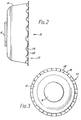
- Figure 2 shows a side view of front portion 4 of the drum 3, showing the opening 6 thereinto.
- the circumferential edge of the drum portion 4 is corrugated, during manufacture, so as to produce an undulating flange 17 having alternate portions either at a first level substantially perpendicular to the surface of the drum portion 4, such as 18, or at a substantially lower level to the edge, such as at 19.
- Figure 3 which is a view in the direction of arrow "A" in Figure 2, also shows the undulating flange 17, around the circumferential edge of the drum portion 4, having alternate portions, 18 and 19, at their respective levels.
- the circumferential edge of the drum portion 5 is correspondingly corrugated to form an undulating flange substantially identical to that shown in Figures 2 and 3, with respect to drum portion 4.
- the two drum portions 4 and 5 are joined together by spot-welding the corresponding flange portions 18 on each drum portion 4 and 5. This causes each of the two corresponding flange portions 19, which are consequently disposed side-by-side, to form apertures around the joining edge of the drum, alternately positioned between the spot-welded 18 of the undulating flange 17.
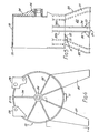
- the tub 8 is preferably supported at the rear portion 10 by leg portions, one being shown generally at 20, which consists of two legs 21 and 22, joined together by a common back plate 23.
- the legs, 21 and 22, comprise flanges, 21a and 21b, and, 22a and 22b, extending out orthogonally from the backplate 23.
- Flanges 21a, 21b, 22a and 22b extend upwardly around the circumference of the tub, into flanges 21c, 21d, 22c and 22d, respectively, so as to cradle the base portion of the tub on one side thereof.
- Figure 1 also shows a number of ridges, two being shown at 24 and 25, which radiate outwardly from the central hub 26.
- the rear portion 10 of the tub 8 is preferably injection-moulded from a plastics material, so that the radial ridges 24 and 25 strengthen the back of the tub and the leg portions, one being shown at 20, which are preferably integrally moulded with the portion 10, provide support therefor.
- Figures 4 to 7 show various views of the rear portion 10 of the tub 8, illustrating the major features thereof.
- the rear end, shown in Figure 4 is provided with a number, preferably seven, of radial ridges, two being shown at 24 and 25, which radiate from the central hub 26, so as to strengthen the back of the tub portion 10, four of these being integrally formed with the leg portion 20 and a second leg portion 27.
- Brackets 28 and 29 which are mounted at the top rear end of the portion 10 are for mounting a removeable detergent dispenser and one or more weights, respectively. The weights assist in maintaining the tub 8 in a static condition, whilst the drum 3 is rotating during operation of the washing machine.
- Figure 5 shows a flange 30 which is provided around the periphery of the open end of the portion 10 and also shows two housings 31 and 32, which are provided adjacent the sump tank outlet 11, for accommodating temperature sensors, to provide control of the temperature of the water within the machine.
- the leg portion 27 consists of a back plate 33 and two orthogonally-disposed flanges, 34 and 35, which extend upwardly, around the circumference of the tub, into flanges, 34a and 35a, so that these flanges cradle the opposite side of the tub to the flanges 21c, 21d, 22c and 22d.
- Figure 6 shows the open end of the portion 10 that joins with the front portion 9 to form the complete tub 8.
- Figure 7 which illustrates a top view of the portion 10, shows a removeable detergent dispenser 36, which may be arranged to dispense powder and/or liquid detergent into the drum 3.
- the portion 10 is provided with three legs 21, 22 and 27, which co-operate with each other so as to balance the tub 8, should it be positioned on an uneven surface.
- any number of legs may be employed, in accordance with the invention.
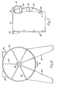
- a sump tank 37 is provided with a water inlet 38 and a water outlet 39.
- a diaphragm fixing plate 40 is held in place by four self-tapping screws or rivets, one shown at 41, and has a microswitch mounting 42 spot-welded thereon.
- a microswitch 43 is mounted on the mounting 42 so that, when the level of water within the tub 8 reaches a predetermined level, the microswitch 43 is actuated, thereby permitting a set wash program for the washing machine to continue.
- FIG. 9 A sectional view of the sump tank assembly is shown in Figure 9.
- a base plate 44 and the sump tank 37 are sealed together by means including a rolled edge, at 51, and the outlet tube 39 is formed with an aperture 50.
- diaphragm 46 which is bonded to a diaphragm plate 47, this plate being in contact with an operating screw 45, which contacts a lever 48.
- Adjusting nut 49 is included, to tighten or slacken the screw 45 which consequently compresses or releases a spring 52, so as to provide adjustment of the pressure at which the microswitch 43 is actuated.
- clothes to be washed are placed in the drum 3 and, during the wash programme, water is pumped into tub 8 and flows into the sump tank 37 and the drum 3, through the apertures disposed around the circumference of the drum, until a water level is reached at which the microswitch 43 is actuated.
- the water is subsequently heated in the drum to wash the clothes, the drum being rotated by the motor and the clothes being agitated by the paddles therewithin.
- the water passes from tub 8 into the sump tank 37, via outlet 11 and inlet 38, and flows out of outlet 39 until the water level is just below the-level of the aperture 50, thereby ensuring that any sediment present in the water remains in the sump tank 37, hence protecting the pump (not shown) which is connected to the outlet 39.
- a further feature which may be incorporated within the present invention, is an electronic switch, such as a mercury switch, for detecting undesirable movement of the machine, due to uneven distribution of the clothes contained therein, and consequently for causing the machine to stop and to revert to a distribution mode in the programme, so as to attempt to re-distribute the clothes. Furthermore the switch can cause the machine to stop if it were overturned, or substantially tilted.
- a mercury switch for detecting undesirable movement of the machine, due to uneven distribution of the clothes contained therein, and consequently for causing the machine to stop and to revert to a distribution mode in the programme, so as to attempt to re-distribute the clothes.
- the switch can cause the machine to stop if it were overturned, or substantially tilted.
- the washing machine in accordance with the invention, is intended to hold a load of approximately 2.7 kgs. and to have a full programme capability, either under mechanical or microprocessor control.
- the spin speed is preferably approximately 500 or 550 revolutions per minute and the drum is filled with cold water only, which is subsequently heated therewithin.
- a series of alternate protruding segments may be provided, so as to produce a "greek fret” design around the periphery of the rear end.
- a supportive "A” frame (not shown) may be provided, upstanding from the base at the rear of the machine, to aid in providing support for the main bearing 14.
- the present invention provides a compact washing machine, which can be manufactured relatively quickly and easily, and thus relatively inexpensively, the additional feature of a substantially free-standing and self-supportive tube obviating the need for a strong, supportive outer casing by which the tub is conventionally supported.
Landscapes
- Engineering & Computer Science (AREA)
- Textile Engineering (AREA)
- Detail Structures Of Washing Machines And Dryers (AREA)
Applications Claiming Priority (4)
| Application Number | Priority Date | Filing Date | Title |
|---|---|---|---|
| GB8314352 | 1983-05-24 | ||
| GB838314352A GB8314352D0 (en) | 1983-05-24 | 1983-05-24 | Washing machines |
| GB838327871A GB8327871D0 (en) | 1983-10-18 | 1983-10-18 | Washing machines |
| GB8327871 | 1983-10-18 |
Publications (1)
| Publication Number | Publication Date |
|---|---|
| EP0127360A2 true EP0127360A2 (de) | 1984-12-05 |
Family
ID=26286218
Family Applications (1)
| Application Number | Title | Priority Date | Filing Date |
|---|---|---|---|
| EP84303190A Withdrawn EP0127360A2 (de) | 1983-05-24 | 1984-05-11 | Waschmaschinen |
Country Status (1)
| Country | Link |
|---|---|
| EP (1) | EP0127360A2 (de) |
Cited By (7)
| Publication number | Priority date | Publication date | Assignee | Title |
|---|---|---|---|---|
| EP0219115A3 (en) * | 1985-10-11 | 1988-01-07 | Zanussi Elettrodomestici S.P.A. | Method for making a laundering tube for a laundry washing machine and laundering tub thus made |
| GB2261881A (en) * | 1991-11-27 | 1993-06-02 | Zanussi Elettrodomestici | Plastics washing tub |
| WO2002022934A3 (en) * | 2000-09-16 | 2002-07-18 | Dyson Ltd | Laundry appliance |
| CN100449050C (zh) * | 2003-12-30 | 2009-01-07 | Lg电子株式会社 | 滚筒式洗衣机的门及制造方法、门的细线板的制造方法 |
| KR100987433B1 (ko) | 2003-07-08 | 2010-10-13 | 엘지전자 주식회사 | 드럼세탁기의 터브 구조 |
| EP2465997A3 (de) * | 2010-12-13 | 2013-06-26 | BSH Bosch und Siemens Hausgeräte GmbH | Hausgerät zur Pflege von Wäschestücken mit einem Laugenbehälter, welcher bewegungsfest mit dem Gehäuse des Hausgeräts verbunden ist |
| EP2975170A1 (de) * | 2014-07-15 | 2016-01-20 | Dongbu Daewoo Electronics Corporation | Waschmaschine und verfahren zur herstellung davon |
-
1984
- 1984-05-11 EP EP84303190A patent/EP0127360A2/de not_active Withdrawn
Cited By (11)
| Publication number | Priority date | Publication date | Assignee | Title |
|---|---|---|---|---|
| EP0219115A3 (en) * | 1985-10-11 | 1988-01-07 | Zanussi Elettrodomestici S.P.A. | Method for making a laundering tube for a laundry washing machine and laundering tub thus made |
| GB2261881A (en) * | 1991-11-27 | 1993-06-02 | Zanussi Elettrodomestici | Plastics washing tub |
| GB2261881B (en) * | 1991-11-27 | 1995-02-15 | Zanussi Elettrodomestici | Plastics tub for washing machine |
| WO2002022934A3 (en) * | 2000-09-16 | 2002-07-18 | Dyson Ltd | Laundry appliance |
| KR100987433B1 (ko) | 2003-07-08 | 2010-10-13 | 엘지전자 주식회사 | 드럼세탁기의 터브 구조 |
| CN100449050C (zh) * | 2003-12-30 | 2009-01-07 | Lg电子株式会社 | 滚筒式洗衣机的门及制造方法、门的细线板的制造方法 |
| EP2465997A3 (de) * | 2010-12-13 | 2013-06-26 | BSH Bosch und Siemens Hausgeräte GmbH | Hausgerät zur Pflege von Wäschestücken mit einem Laugenbehälter, welcher bewegungsfest mit dem Gehäuse des Hausgeräts verbunden ist |
| EP2975170A1 (de) * | 2014-07-15 | 2016-01-20 | Dongbu Daewoo Electronics Corporation | Waschmaschine und verfahren zur herstellung davon |
| CN105274779A (zh) * | 2014-07-15 | 2016-01-27 | 东部大宇电子株式会社 | 洗衣机和制造洗衣机的方法 |
| US9517585B2 (en) | 2014-07-15 | 2016-12-13 | Dongbu Daewoo Electronics Corporation | Washing machine and method of manufacturing the same |
| CN105274779B (zh) * | 2014-07-15 | 2017-12-26 | 东部大宇电子株式会社 | 洗衣机和制造洗衣机的方法 |
Similar Documents
| Publication | Publication Date | Title |
|---|---|---|
| EP1111119B1 (de) | Trommelwaschmaschine mit Trübungssensor | |
| AU2004237865B9 (en) | Drum type washer | |
| CN107488994B (zh) | 衣物处理装置的排水泵 | |
| US5685623A (en) | Appliance top assembly | |
| EP0127360A2 (de) | Waschmaschinen | |
| EP3124684B1 (de) | Wäschetrockner | |
| EP3279388B1 (de) | Kleidungsbehandlungsvorrichtung | |
| CN112962264B (zh) | 洗衣设备 | |
| US4125003A (en) | Sump strainer for tumbler washing machine | |
| US20060081014A1 (en) | Washing apparatus | |
| JPH10263284A (ja) | ドラム式洗濯機 | |
| US4483161A (en) | Washing apparatus | |
| KR101756407B1 (ko) | 세탁기 | |
| US9189970B2 (en) | Miniature of washing machine for exhibition | |
| EP3526388B1 (de) | Waschmaschine | |
| US3585822A (en) | Propulsion system for automatic washer | |
| JP7690616B2 (ja) | インターフェース及びインターフェースが備えられた衣類処理装置 | |
| EP1152082B1 (de) | Von oben beschickbarer Wäschewaschtrockner mit horizontaler Trommelachse | |
| EP3124683A1 (de) | Wäschetrockner | |
| JP3439156B2 (ja) | 洗濯機 | |
| GB769040A (en) | Improvements in and relating to dish washing machines | |
| JP2700361B2 (ja) | 洗濯機 | |
| KR20210120297A (ko) | 의류처리장치 및 의류처리장치의 제어방법 | |
| US12460342B2 (en) | Clothes treatment apparatus | |
| EP3090854A1 (de) | Haushaltsgerät mit steuerungsleiterplatte |
Legal Events
| Date | Code | Title | Description |
|---|---|---|---|
| PUAI | Public reference made under article 153(3) epc to a published international application that has entered the european phase |
Free format text: ORIGINAL CODE: 0009012 |
|
| AK | Designated contracting states |
Designated state(s): DE FR GB IT SE |
|
| RAP1 | Party data changed (applicant data changed or rights of an application transferred) |
Owner name: THORN EMI APPLIANCES LIMITED |
|
| STAA | Information on the status of an ep patent application or granted ep patent |
Free format text: STATUS: THE APPLICATION HAS BEEN WITHDRAWN |
|
| 18W | Application withdrawn |
Withdrawal date: 19860715 |
|
| RIN1 | Information on inventor provided before grant (corrected) |
Inventor name: ROYLE, TERENCE GORDON Inventor name: YOWARD, NICHOLAS LLOYD |