EP0126291A2 - Soupape commandée par un fluide sous pression - Google Patents
Soupape commandée par un fluide sous pression Download PDFInfo
- Publication number
- EP0126291A2 EP0126291A2 EP84104262A EP84104262A EP0126291A2 EP 0126291 A2 EP0126291 A2 EP 0126291A2 EP 84104262 A EP84104262 A EP 84104262A EP 84104262 A EP84104262 A EP 84104262A EP 0126291 A2 EP0126291 A2 EP 0126291A2
- Authority
- EP
- European Patent Office
- Prior art keywords
- valve
- connecting line
- line
- piston chamber
- control valve
- Prior art date
- Legal status (The legal status is an assumption and is not a legal conclusion. Google has not performed a legal analysis and makes no representation as to the accuracy of the status listed.)
- Granted
Links
Images

Classifications
-
- F—MECHANICAL ENGINEERING; LIGHTING; HEATING; WEAPONS; BLASTING
- F01—MACHINES OR ENGINES IN GENERAL; ENGINE PLANTS IN GENERAL; STEAM ENGINES
- F01D—NON-POSITIVE DISPLACEMENT MACHINES OR ENGINES, e.g. STEAM TURBINES
- F01D21/00—Shutting-down of machines or engines, e.g. in emergency; Regulating, controlling, or safety means not otherwise provided for
- F01D21/20—Checking operation of shut-down devices
-
- F—MECHANICAL ENGINEERING; LIGHTING; HEATING; WEAPONS; BLASTING
- F16—ENGINEERING ELEMENTS AND UNITS; GENERAL MEASURES FOR PRODUCING AND MAINTAINING EFFECTIVE FUNCTIONING OF MACHINES OR INSTALLATIONS; THERMAL INSULATION IN GENERAL
- F16K—VALVES; TAPS; COCKS; ACTUATING-FLOATS; DEVICES FOR VENTING OR AERATING
- F16K31/00—Actuating devices; Operating means; Releasing devices
- F16K31/12—Actuating devices; Operating means; Releasing devices actuated by fluid
- F16K31/122—Actuating devices; Operating means; Releasing devices actuated by fluid the fluid acting on a piston
- F16K31/1223—Actuating devices; Operating means; Releasing devices actuated by fluid the fluid acting on a piston one side of the piston being acted upon by the circulating fluid
Definitions
- the invention relates to a pressure medium-operated valve with a housing, which has an inlet connection connected to a pressure medium source, an outlet connection and a cylinder shielded from the flow through the valve space, with a closure part arranged in the pressure region of the inlet connection, which is connected by means of a rod with a servo which is arranged displaceably in the cylinder.
- Piston is connected, the piston dividing the cylinder into a first piston chamber, which increases in the transition from a working position to a safety position, and a second piston chamber, which decreases in the transition from the working position to the safety position, with at least one spring arranged in the cylinder , which loads the piston with the rod and the closure part in the direction of the safety position of the valve, with two relief lines each containing a control valve, which on the two piston chambers are connected and lead to at least one pressure medium sink, preferably the atmosphere, with a first connecting line containing a control valve between the pressure area of the inlet connector and the first piston chamber and with a second connecting line containing a control valve between the pressure area of the inlet connector and the second piston chamber.
- Such a valve is known, the closure part of which can be moved in the connecting or relief lines by opening and closing the control valves, the closing and opening times of the closure part being constant and of the design parameters of the valve, in particular of the pressure conditions and of the Valve dimensions, depend.
- the closing and opening times cannot be changed easily, which is further supported by the fact that the control valves are mostly designed as simple, remote-controlled solenoid valves that are reliable, robust and inexpensive, but only the two positions can take "open” and "closed”; they do not permit simple adjustment of the opening cross section. With regard to the normal operation of the valve, however, this is satisfactory and guarantees predictable operating conditions.
- valve used as a safety valve has to be checked for its functionality with a certain frequency with regard to special requirements for operational safety.
- the frequent actuation of such valves for testing purposes under the conditions prevailing during normal operation places a heavy load on the seat surfaces in the valve due to the abrupt closing process, so that an increase in the risk of leaks and thus a considerable reduction in the service life of the valve can occur through rapid wear of the seat surfaces.
- there is an increased stress on the pressure line connected to the valve due to the frequent pressure surges as a result of the abrupt closing process.
- valve should therefore be able to be moved into the safety position both quickly and slowly as required.
- One way to achieve this is to provide at least one second control valve, which is connected in parallel with the already existing control valve, in the relief line of the second piston chamber and / or in the first connecting line, the additional control valve having a smaller flow cross-section than the already existing control valve.
- the control valve with the larger flow cross-section for normal operation and the control valve with the smaller flow cross-section can optionally be operated for the function test.
- this object is achieved in that the second connecting line has a non-return valve through which flow can be made in the direction of the second piston chamber, and in that a third connecting line is provided which connects a first cavity section to a second cavity section, the first cavity section extending over the interior of the first connecting line, extends the first piston chamber and the interior of the relief line connected to this space to the cylinder-side end of the control valve located in this relief line and the second cavity section from the cylinder-side end of the check valve in the second connecting line via the second piston chamber to the cylinder-side end of the control valve in the to discharge line connected to the second piston chamber is sufficient.
- the third connection line can be between the first and the second connection line or between be attached to the two relief lines or also exist in a bore in the piston connecting the two piston chambers, so that the designer has great freedom in the design of the valve. Another advantage is that the behavior of the valve during test operation can be calculated in advance.
- control valves according to claim 2 can be used both in normal and test mode and allows a simultaneous actuation of two control valves with a single control line for both operating modes.
- pairing of the control valves reduces the possibility of errors when operating the valve.
- the embodiment according to claim 3 makes it possible to move the closure part of the valve into the working position with the help of foreign medium when there is no pressure in the pressure medium system.
- a particularly simple, safe and inexpensive supply of foreign medium can be realized according to the feature of claim 4, while the preloading according to claim 5 clearly defines the behavior of the foreign medium supply in the depressurized state of the valve, so that undesired positions of the closure part of the double-acting check valve are avoided .
- control valve arrangement secures the piston chambers against any undesired exposure to pressure media, which enables a particularly precise control of the valve, even during the functional test.
- precise control or control accuracy is meant the size of the spreading area within which the closing and opening times vary can. It is very important to adhere to very small scattering ranges, because important deviations from the normal closing time can be drawn from the friction and tightness conditions within the valve.
- control accuracy is further increased by the feature according to claim 7, in that the throttle point in the first connecting line allows a better pre-calculation and calibration of the quantity of pressure medium flowing through.
- the arrangement according to claim 8 makes the pressure medium flow in test mode independent of the pressure medium flow optimized for normal operation through the throttle point in the first connecting line. Thanks to the throttle point in the third connecting line, the pressure medium flow required for the test operation can be calculated very precisely in advance and verified, so that the time required for the transition to the safety position of the closure part in the test operation can be determined in advance with very high accuracy.
- the pressure medium flow emerging from the first piston chamber at the transition of the valve into the working position can be better calculated and the verifiability of the medium flow flowing in the relief line is increased. This makes it easier to control the behavior of the valve during the transition to the working position - both in test and normal operation.
- An additional advantage arises from the fact that, if a throttling is selected that is sufficiently strong, it becomes possible to continuously pressurize the valve in the valve To maintain the safety position, even in the event of a failure or tearing of the control valve in the relevant relief line.
- the third connecting line connected to the first and second cavity section is on the cylinder side of the in the first control line located control valve and the control valve located in the second connection line connected to the cavity section in question.
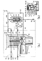
- FIG. 1 serves for a simplified explanation, because in the practical implementation of the valve all control and check valves as well as the lines with the throttling points can be contained within the contour of the valve.
- a valve 1 has a housing 10 and a cover 20 which is fastened tightly to the housing 10 by means of screws, not shown.
- Pressure medium from a pressure medium source flows through an inlet connection 11 of the housing 10 and leaves the valve via an outlet connection 12
- Closure part 13 is movably arranged in the pressure area of the inlet connector 11 and has a conical sealing surface 14 on the side facing the outlet connector 12, which comes to rest on a sealing seat 15 in the housing 10 when the valve 1 is closed.
- the closure part 13 On the side of the closure part 13 facing away from the outlet connection 12, the closure part 13 has a rear seat 16 which, in the completely open position of the closure part 13, bears tightly against a stop surface 17 in the housing 10.
- the housing 10 has a cylinder 2, which extends towards the cover 20 and in which a servo piston 24 is movably arranged.
- the piston 24 is fixedly connected to the closure part 13 by means of a rod 23 and divides the space enclosed by the cylinder 2 into a first piston chamber 21 and a second piston chamber 22.
- the rod 23 penetrates a cylinder base 18 which separates the second piston chamber from the pressure area of the inlet connector 11 separates in each position of the closure part 13. In the bottom 18, not shown, the rod 23 surrounding sealing means are provided.
- a helical compression spring 25 is provided, which is supported between the cover 20 and the bottom of a bore 26 which extends through the piston 24 into the rod 23.
- the pressure in the pressure area of the inlet connection 11 is transmitted to a distribution line 40 connected to the housing 10.
- the distribution line 40 is connected to the first piston chamber 21 by means of a first connecting line 41 and to the second piston chamber 22 by means of a second connecting line 42.
- the first connection line 41 and the second connection Line 42 are connected to each other via a third connecting line 43, which consists of two sections 43a and 43b.
- the first piston chamber 21 is connected to a pressure medium sink, here the atmosphere, via a relief line 44 containing a magnetic control valve 441.
- the relief line 44 has a throttle point 442 between the control valve 441 and the first piston chamber 21.
- the second piston chamber 22 is connected via a relief line 45 to a pressure medium sink, here also the atmosphere.
- the relief line 45 has a solenoid control valve 451.
- the first connecting line 41 contains two magnetic control valves 411 and 413 connected in parallel, which lie between the connection point of the section 43b and the first piston chamber 21. In addition, it contains a throttle point 412, which is arranged between the connection point on the distribution line 40 and that of the section 43b. A throttle point 432 is also located in section 43b.
- the second connecting line 42 has a magnetic control valve 421, which lies between the second piston chamber 22 and the connection point of the section 43a. It also has a check valve 422 which can flow through in the direction of the second piston chamber 22 and is located between the connection points on the section 43 a and on the distribution line 40.
- a double-acting check valve 3 which consists of a housing 31, a closure plate 32 and a spring 33.
- the Housing 31 is connected to section 43b via a bore 34, whereas a bore 35 connected to an external medium line 46 is provided at the other end of this housing.
- the housing 31 also contains a third bore 36, which is made between the two bores 34 and 35 and is connected to the section 43a.
- the spring 33 loads the closure plate 32 in the direction of the bore 35.
- the closure plate 32 On each of the two end faces, the closure plate 32 has a sealing surface which, in one extreme position of the plate, has a sealing seat 37 on the bore 34 and in the other extreme position with a Seal seat 38 cooperate on the bore 35.
- the locking plate 32 which can be moved in the housing 31 between two extreme positions, either shuts off the bore 35, with the bores 34 and 36 communicating with one another (drawn position in FIG. 1), or it shuts off the bore 34, with the bores 35 and 36 communicating with one another .
- the solenoid control valves 441, 411 and 413 are actuated simultaneously by a single control line 51, the solenoid control valve 441 being closed and the solenoid control valves 411 and 413 being open when the line 51 is de-energized.
- the solenoid control valves 451 and 421 are likewise actuated simultaneously by a single control line 52, in that the solenoid control valve 451 is open or the solenoid control valve 421 is closed when the line 52 is de-energized.
- the connecting lines 41 and 42, and the sections 43a and 43b, up to the solenoid control valves 411, 413 and 421 there is approximately the same medium pressure as in the inlet connection 11.
- the foreign medium line 46 is depressurized because a valve 50 in this line shuts off the supply of foreign medium.
- the closure plate 32 is therefore pressed tightly against the sealing seat 38 by the pressure of the medium in the housing 31 and by the spring 33.
- the closing of the valve 1 is either by the operating personnel or automatically by an accident in the System triggered, the current in the control line 51 being turned off. This closes the solenoid control valve 441 and the solenoid control valves 411 and 413 open. In a fraction of a second, which depends on the cross-section of the throttle point 412, pressure medium flows via the lines 40 and 41 into the first piston chamber 21. As a result, the piston 24 together with the rod 23 and the closure part 13 are inserted into the closing, ie Safety position pushed. If the control line 51 is now energized again, the solenoid control valve 441 opens and the solenoid control valves 411 and 413 close, so that the pressure in the first piston chamber 21 drops to atmospheric pressure.
- control line 52 is also energized, so that solenoid control valve 451 closes and solenoid control valve 421 opens. Pressure medium thus enters the second piston chamber 22, whereby movement of the closure part 13 in the opening direction is initiated.
- the control line 52 is de-energized again, so that the solenoid control valve 451 opens and the solenoid control valve 421 closes. This restores the normal operating conditions.
- the throttle point 442 limits the amount of medium flowing out of the first piston chamber 21 per second in order to increase the opening time of the valve 1 and thereby to avoid pressure surges in the pressure lines of the system.
- the throttle point 442 also has the important task of enabling the valve l to be closed and kept closed in the event of failure and even total destruction of the solenoid control valve 441, by pressure build-up in the first piston chamber 21 with constant refilling of pressure medium via the then opened solenoid control valves 411 and 413 allowed.
- valve 1 The functionality of valve 1 is checked in two steps.
- a first step the control line 52 is energized, whereby the solenoid control valve 451 is closed and the solenoid control valve 421 is opened.
- the second piston chamber 22 fills with pressure medium, which forms a pressure cushion.
- the control line 51 is de-energized, whereupon the solenoid control valve 441 closes and the solenoid control valves 411 and 413 open.
- the first piston chamber 21 is now also acted upon by pressure medium, and there is approximately the same pressure in the piston chambers 21 and 22 as in the inlet port 11. The forces acting on the moving parts in terms of pressure are thus largely balanced and only the force of the helical compression spring 25 tries to close valve 1.
- Pressure medium flows from the second piston chamber 22 via the second connecting line 42, the section 43a of the third connecting line 43, the double-acting check valve 3, the throttle point 432 in section 43b and the first connecting line 41 into the first piston chamber 21, the valve 1 closing slowly .
- the closing speed is primarily determined by the amount of pressure medium let through by the throttle point 432 per unit of time.
- the check valve 422 prevents pressure medium from flowing out of the second piston chamber 22 into the distribution line 40.
- the necessary additional quantity for filling the first piston chamber 21 is supplied via the lines 40 and 41 from the pressure area of the inlet connection 11.
- Essential in the test mode are: first, the pre-formation of a pressure cushion in the second piston chamber 22, as a result of which the valve 1 is closed in a controlled manner is much easier, and secondly, the determination of the flow rate from the second piston chamber 22 to the first piston chamber 21 by means of the single throttle point 432, as a result of which the closing time of the valve 1 can be determined very precisely.
- the closing time can be measured in a known manner and possible deviations of the measured value from a target value can provide important information with regard to any defects in the valve 1, such as leaks, contamination or deformations.
- valve 1 If there is no pressure in the pressure area of the inlet connection 11, there is also no pressure in all other lines and spaces of the valve 1.
- the valve 1 is then kept closed by means of the helical compression spring 25 and the closure remains by the spring 33 plate 32 of the double-acting check valve 3 in its normal position shown in FIG. 1, in which the foreign medium line 46 is shut off.
- the valve 1 can then only be opened by introducing foreign medium via the foreign medium line 46.
- the control line 52 is first energized, so that the solenoid control valve 451 closes and the solenoid control valve 421 opens. By opening the valve 50, the foreign medium line 46 is connected to a foreign medium source, not shown.
- the foreign medium pressure acts on the closure plate 32 via the bore 35 and moves it against the action of the spring 33 to the sealing seat 37 at the bore 34.
- the foreign medium now flows through the bore 36, the section 43a, and the second connecting line 42 into the second Piston chamber 22, the piston 24 and thus the closure part 13 being pushed into the open position.
- the closure plate 32 and the check valve 422 prevent foreign medium from entering the section 43b and the lines 41 and 40.
- valve 1 For safety reasons, various redundancies can be provided on valve 1. In the embodiment according to FIG. 1, only the magnets connected in parallel are Control valves 411 and 413 are available as an example of such redundancy because the safety requirements there are particularly high. Depending on requirements and spatial conditions, however, further redundancies can be provided, for example also two parallel helical compression springs 25.
- the invention is implemented in its simplest form, wherein - as in FIG. 1 - the open position of the valve 1 is its working position.
- a foreign medium supply is missing in all four examples.
- FIGS. 3a to 3d correspond in their simplicity to those according to FIGS. 2a to 2d, but they are closed in their working position and the open position is their safety position.
- valves 1 are in their working position. Their functioning results from the description of FIG. 1. Only the examples according to FIGS. 2b, 3c and 3d have a special feature in that they only remain in the working position when the second piston chamber 22 is under pressure. In contrast to the other examples, this means that in the working position of the valve 1 in FIGS. 2b, 3c and 3d, the solenoid control valve 451 must be closed and the solenoid control valve 421 must be open, and that the solenoid control valve 451 must be open during the transition to the safety position and that Solenoid control valve 421 are closed. For this they have to Solenoid control valves 451 and 421 are not actuated during the function test.
- FIGS. 2a to 2d and 3a to 3d thus show the variety of possible applications of the invention when a pressure medium operated valve is to be operated with two different opening or closing times.
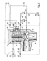
- FIG. 4 largely corresponds to the example according to FIG. 2, but a foreign medium line 46 is provided, which is connected to the third connecting line 43 via a check element 47.
- the check element 47 can be flowed through in the direction of the line 43.
- a non-return element 48 is provided in the first connecting line 41, namely upstream of the connection point of the third connecting line 43.
- the non-return element can be flowed through in the direction of the connection point just mentioned.
- normal closing elements can also be used.
- the embodiments according to FIGS. 2b to 2d and FIGS. 3a to 3d can also be provided with a foreign medium supply.
- the two cavity sections are connected to one another via a third connecting line 43, which has two openings on the cylinder side of the control valves 411 and 413 provided in the first connecting line 41 and the control valve 421 provided in the second connecting line 42.
- the third connecting line extends for the most part through the wall of the cylinder 2.
- the one having the throttle point 431 Section of the third connecting line 43 is formed in a wall part 19, which is releasably attached to the outside of the cylinder 2 by means of screws, not shown. This allows the throttle to be replaced easily, either for the purpose of replacement by a throttle of the same size or for the purpose of replacement by a throttle with a larger or smaller passage cross section.
- valve according to FIG. 5 is open, the same conditions are present as have been described for the valve according to FIG. 1. 5 is either triggered by the operating personnel or automatically by a fault in the system, the current in the control line 51 being switched off. This closes the solenoid control valve 441 and the solenoid control valves 411 and 413 open. In a fraction of a second, which is dependent on the cross section of the throttle point 412, pressure medium flows via the lines 40 and 41 into the first piston chamber 21. As a result, the servo piston 24 together with the rod 23 and the closure part 13 are displaced downward, ie in Direction of the closing or safety position.
- the full pressure of the pressure medium in the first piston chamber 21 initially acts on the piston 24, while this pressure is not yet effective in the second piston chamber 22 because of the throttle point 431 in the third connecting line 43.
- the piston 24 thus initially moves relatively rapidly downward, the second piston chamber 22 shrinking and a pressure being established in it, which lies between the pressure in the first piston chamber and the atmospheric pressure. Some pressure medium escapes via the relief line 45.
- pressure medium also penetrates into the second piston chamber 22 via the third connecting line 43, so that the pressure in this piston chamber increases somewhat. This will make the piston Movement is initially easy and then increasingly braked, ie the moving system reaches the lower end position at a constantly decreasing speed.
- the closure part 13 is thus placed on the seat surface 15 without damage to this seat surface or to the sealing surface 14 occurring.
- the braking effect is determined by the dimensioning of the cross sections of the throttle points 431 and 452.
- control line 51 is now energized again, the solenoid control valve 441 opens and the solenoid control valves 411 and 413 close, so that the pressure in the first piston chamber 21 drops to atmospheric pressure.
- control line 52 is also energized, so that solenoid control valve 451 closes and solenoid control valve 421 opens.
- Pressure medium thus enters the second piston chamber 22, whereby movement of the closure part 13 in the opening direction is initiated. With this opening movement, a braking effect of the movable system occurs in the same way as described above for the downward movement.
- control line 52 is de-energized again, so that the solenoid control valve 451 opens and the solenoid control valve 421 closes. This restores the normal operating conditions.
- the throttle point 442 also has the important task of enabling the valve 1 to be closed and kept closed in the event of failure and even total destruction of the solenoid control valve 441, by pressure build-up in the first piston chamber 21 with constant refilling of pressure medium via the then opened solenoid control valves 411 and 413 allowed.
Applications Claiming Priority (4)
| Application Number | Priority Date | Filing Date | Title |
|---|---|---|---|
| CH2731/83 | 1983-05-19 | ||
| CH273183A CH661333A5 (en) | 1983-05-19 | 1983-05-19 | Pressure-operated valve device |
| CH410/84 | 1984-01-10 | ||
| CH41084A CH663993A5 (de) | 1984-01-30 | 1984-01-30 | Druckmediumbetaetigtes ventil. |
Publications (3)
| Publication Number | Publication Date |
|---|---|
| EP0126291A2 true EP0126291A2 (fr) | 1984-11-28 |
| EP0126291A3 EP0126291A3 (en) | 1985-08-14 |
| EP0126291B1 EP0126291B1 (fr) | 1988-07-27 |
Family
ID=25684495
Family Applications (1)
| Application Number | Title | Priority Date | Filing Date |
|---|---|---|---|
| EP84104262A Expired EP0126291B1 (fr) | 1983-05-19 | 1984-04-14 | Soupape commandée par un fluide sous pression |
Country Status (5)
| Country | Link |
|---|---|
| US (1) | US4552330A (fr) |
| EP (1) | EP0126291B1 (fr) |
| CA (1) | CA1215289A (fr) |
| DE (1) | DE3473023D1 (fr) |
| ES (1) | ES8605324A1 (fr) |
Cited By (2)
| Publication number | Priority date | Publication date | Assignee | Title |
|---|---|---|---|---|
| WO1987004224A1 (fr) * | 1985-12-29 | 1987-07-16 | Központi Bányászati Fejlesztési Intézet | Dispositif d'actionnement pour des alimentateurs de chambres tubulaires d'equipements de transport hydrauliques |
| WO1987004499A1 (fr) * | 1986-01-20 | 1987-07-30 | Dominator Maskin Ab | Procede et agencement pour modifier la pression dans des systemes pneumatiques ou hydrauliques |
Families Citing this family (20)
| Publication number | Priority date | Publication date | Assignee | Title |
|---|---|---|---|---|
| US4852850A (en) * | 1987-05-14 | 1989-08-01 | Westinghouse Electric Corp. | Valve system with adjustable seating force |
| US5139663A (en) * | 1991-03-14 | 1992-08-18 | Microlift Systems Limited Partnership | Discharge valve for dissolved air flotation |
| US5275136A (en) * | 1991-06-24 | 1994-01-04 | Ford Motor Company | Variable engine valve control system with hydraulic damper |
| DE69122411T2 (de) * | 1991-11-29 | 1997-02-06 | Caterpillar Inc | Hydraulischer brennkraftmaschinenventilsitzdaempfer |
| US6457696B1 (en) * | 1998-11-06 | 2002-10-01 | Tgk Co., Ltd. | Pilot operated flow regulating valve |
| IT1310675B1 (it) * | 1999-08-06 | 2002-02-19 | Merlo Spa | Raccordo ad innesto rapido per circuiti a fluido |
| US6749173B2 (en) * | 2002-09-27 | 2004-06-15 | The Hartfiel Company | Valve arrangement and method of directing fluid flow |
| DE102009014570A1 (de) * | 2009-03-17 | 2010-09-23 | E.G.O. Elektro-Gerätebau GmbH | Verfahren zur Steuerung einer Kochstelle eines Gasherdes sowie Vorrichtung |
| GB2498545A (en) * | 2012-01-18 | 2013-07-24 | Babcock Integrated Technology Ltd | Flood control valve assembly |
| CN104583655A (zh) * | 2012-07-09 | 2015-04-29 | 诺格伦公司 | 电磁体辅助的压力致动阀 |
| DE102012021388B4 (de) * | 2012-10-31 | 2022-02-03 | Samson Aktiengesellschaft | Pneumatisches Antriebssystem und Verfahren zum Betreiben des pneumatischen Antriebssystems |
| US9915371B2 (en) * | 2014-11-25 | 2018-03-13 | Parker-Hannifin Corporation | Hydraulic port safety locking device |
| US9939068B2 (en) * | 2015-07-06 | 2018-04-10 | Emerson Process Management Regulator Technologies, Inc. | Fluid control apparatus having flow restrictors |
| US10317917B2 (en) | 2015-07-06 | 2019-06-11 | Emerson Process Management Regulator Technologies, Inc. | Fluid control apparatus having variable area flow restrictor |
| EP3130829B1 (fr) * | 2015-08-12 | 2018-08-15 | General Electric Technology GmbH | Vanne |
| JP7207999B2 (ja) * | 2018-12-28 | 2023-01-18 | 三菱重工業株式会社 | 蒸気弁、発電システム、及び蒸気弁の検査方法 |
| US20220213979A1 (en) * | 2019-05-17 | 2022-07-07 | Lam Research Corporation | Cooling of air actuated valve using actuating air |
| EP3745007A1 (fr) * | 2019-05-29 | 2020-12-02 | Microtecnica S.r.l. | Soupape de décharge de pression |
| JP2021134808A (ja) * | 2020-02-25 | 2021-09-13 | 東京エレクトロン株式会社 | バルブ装置 |
| US20220196181A1 (en) * | 2020-12-23 | 2022-06-23 | Goodrich Corporation | Inflatable systems with electro-pneumatic valve modules |
Citations (6)
| Publication number | Priority date | Publication date | Assignee | Title |
|---|---|---|---|---|
| DE818195C (de) * | 1948-10-02 | 1951-10-22 | Siemens Schuckertwerke A G | Hilfsgesteuertes Sicherheitsventil |
| CH528693A (de) * | 1970-09-01 | 1972-09-30 | Sulzer Ag | Sicherheitsvorrichtung mit einem Ventil, vorzugsweise Absperrventil |
| US3907248A (en) * | 1973-07-20 | 1975-09-23 | Coulbeck M G Ltd | Stopcocks |
| DE2514688B2 (de) * | 1975-03-20 | 1977-05-26 | Gebrüder Sulzer AG, Winterthur (Schweiz) | Schnellschlussventil, insbesondere dampfisolierventil |
| US4240463A (en) * | 1979-07-27 | 1980-12-23 | Otis Engineering Corporation | Safety valve actuator and pilot system |
| EP0054602A1 (fr) * | 1980-12-19 | 1982-06-30 | GebràDer Sulzer Aktiengesellschaft | Soupape d'arrêt contrôlée par son propre fluide |
Family Cites Families (7)
| Publication number | Priority date | Publication date | Assignee | Title |
|---|---|---|---|---|
| US2587539A (en) * | 1946-09-07 | 1952-02-26 | Seaman Henry | Hydraulically balanced valve system |
| US2780204A (en) * | 1953-12-29 | 1957-02-05 | Harris Seybold Co | Hydraulic motive power system |
| US2830784A (en) * | 1954-09-30 | 1958-04-15 | Placette Theodore | General purpose flow valve with alternative fluid pressure or manual control |
| US2986368A (en) * | 1958-07-24 | 1961-05-30 | Orenda Engines Ltd | Valve |
| US3491982A (en) * | 1968-02-19 | 1970-01-27 | Lucas Industries Ltd | Piston operated valve with relatively movable sleeve |
| US3746299A (en) * | 1971-07-19 | 1973-07-17 | Westinghouse Electric Corp | Quick operating device for a valve |
| US3892381A (en) * | 1973-10-23 | 1975-07-01 | Atwood & Morrill Co Inc | Fail-safe valve |
-
1984
- 1984-04-14 EP EP84104262A patent/EP0126291B1/fr not_active Expired
- 1984-04-14 DE DE8484104262T patent/DE3473023D1/de not_active Expired
- 1984-04-25 CA CA000452686A patent/CA1215289A/fr not_active Expired
- 1984-05-04 ES ES532216A patent/ES8605324A1/es not_active Expired
- 1984-05-17 US US06/611,091 patent/US4552330A/en not_active Expired - Lifetime
Patent Citations (6)
| Publication number | Priority date | Publication date | Assignee | Title |
|---|---|---|---|---|
| DE818195C (de) * | 1948-10-02 | 1951-10-22 | Siemens Schuckertwerke A G | Hilfsgesteuertes Sicherheitsventil |
| CH528693A (de) * | 1970-09-01 | 1972-09-30 | Sulzer Ag | Sicherheitsvorrichtung mit einem Ventil, vorzugsweise Absperrventil |
| US3907248A (en) * | 1973-07-20 | 1975-09-23 | Coulbeck M G Ltd | Stopcocks |
| DE2514688B2 (de) * | 1975-03-20 | 1977-05-26 | Gebrüder Sulzer AG, Winterthur (Schweiz) | Schnellschlussventil, insbesondere dampfisolierventil |
| US4240463A (en) * | 1979-07-27 | 1980-12-23 | Otis Engineering Corporation | Safety valve actuator and pilot system |
| EP0054602A1 (fr) * | 1980-12-19 | 1982-06-30 | GebràDer Sulzer Aktiengesellschaft | Soupape d'arrêt contrôlée par son propre fluide |
Cited By (3)
| Publication number | Priority date | Publication date | Assignee | Title |
|---|---|---|---|---|
| WO1987004224A1 (fr) * | 1985-12-29 | 1987-07-16 | Központi Bányászati Fejlesztési Intézet | Dispositif d'actionnement pour des alimentateurs de chambres tubulaires d'equipements de transport hydrauliques |
| WO1987004499A1 (fr) * | 1986-01-20 | 1987-07-30 | Dominator Maskin Ab | Procede et agencement pour modifier la pression dans des systemes pneumatiques ou hydrauliques |
| AU601390B2 (en) * | 1986-01-20 | 1990-09-13 | Dominator Maskin Ab | Method and arrangement for controlled application of supply pressure to pneumatic/hydraulic devices |
Also Published As
| Publication number | Publication date |
|---|---|
| EP0126291A3 (en) | 1985-08-14 |
| ES8605324A1 (es) | 1986-03-16 |
| EP0126291B1 (fr) | 1988-07-27 |
| CA1215289A (fr) | 1986-12-16 |
| DE3473023D1 (en) | 1988-09-01 |
| ES532216A0 (es) | 1986-03-16 |
| US4552330A (en) | 1985-11-12 |
Similar Documents
| Publication | Publication Date | Title |
|---|---|---|
| EP0126291B1 (fr) | Soupape commandée par un fluide sous pression | |
| EP0496021B1 (fr) | Soupape d'arrêt pour système hydraulique de sécurité | |
| DE3323363A1 (de) | Vorgesteuertes druckreduzierventil | |
| EP0177620B1 (fr) | Soupape actionnée par un fluide sous pression | |
| DE1916266A1 (de) | Elektrohydraulisches Stellgeraet | |
| DE3901475A1 (de) | Fluidgesteuerte servoanordnung | |
| EP1519866B1 (fr) | Dispositif de ventilation d'un cylindre de freinage | |
| EP0540963A1 (fr) | Système d'alimentation pour système hydraulique divisé | |
| EP0054602A1 (fr) | Soupape d'arrêt contrôlée par son propre fluide | |
| DE1918875A1 (de) | Schieberventil fuer Gase,Fluessigkeiten und Gas-Feststoff-Gemische | |
| CH661333A5 (en) | Pressure-operated valve device | |
| DE3239930A1 (de) | Hydraulisch steuerbares sperrventil, insbesondere fuer die rohrbruchsicherung | |
| EP0111617B1 (fr) | Dispositif opérateur actionné par fluide sous pression avec organe de verrouillage | |
| DE1945951A1 (de) | Entsperrbares Rueckschlagventil | |
| DE102006054122A1 (de) | Fluidisches System, Schaltungsanordnung sowie Verfahren zum Betrieb eines fluidischen Systems | |
| EP0717201B1 (fr) | Système de protection dans une installation sous pression | |
| DE4320937A1 (de) | Stellantrieb für ein Regelventil | |
| EP0617202B1 (fr) | Dispositif amortisseur de fin de course pour un système mobile | |
| DE4235068A1 (de) | Schnell schließendes Ventil | |
| DE3812116A1 (de) | Elektrohydraulisches wegeventil | |
| DE2915505C2 (fr) | ||
| EP1415095A1 (fr) | Dispositif de commande destinee au mouvement continu d'un moteur d'un servomoteur hydraulique | |
| DE2104362A1 (de) | Druckventil fuer hydraulische anlagen | |
| DE2827128A1 (de) | Kompaktes, vorgesteuertes druckbegrenzungsventil | |
| DE1775203A1 (de) | Vorrichtung zur Steuerung eines in beide Richtungen arbeitenden hydraulischen Antriebes |
Legal Events
| Date | Code | Title | Description |
|---|---|---|---|
| PUAI | Public reference made under article 153(3) epc to a published international application that has entered the european phase |
Free format text: ORIGINAL CODE: 0009012 |
|
| AK | Designated contracting states |
Designated state(s): BE DE FR GB SE |
|
| PUAL | Search report despatched |
Free format text: ORIGINAL CODE: 0009013 |
|
| AK | Designated contracting states |
Designated state(s): BE DE FR GB SE |
|
| 17P | Request for examination filed |
Effective date: 19860116 |
|
| 17Q | First examination report despatched |
Effective date: 19870305 |
|
| GRAA | (expected) grant |
Free format text: ORIGINAL CODE: 0009210 |
|
| AK | Designated contracting states |
Kind code of ref document: B1 Designated state(s): BE DE FR GB SE |
|
| GBT | Gb: translation of ep patent filed (gb section 77(6)(a)/1977) | ||
| REF | Corresponds to: |
Ref document number: 3473023 Country of ref document: DE Date of ref document: 19880901 |
|
| ET | Fr: translation filed | ||
| PLBE | No opposition filed within time limit |
Free format text: ORIGINAL CODE: 0009261 |
|
| STAA | Information on the status of an ep patent application or granted ep patent |
Free format text: STATUS: NO OPPOSITION FILED WITHIN TIME LIMIT |
|
| 26N | No opposition filed | ||
| EAL | Se: european patent in force in sweden |
Ref document number: 84104262.5 |
|
| PGFP | Annual fee paid to national office [announced via postgrant information from national office to epo] |
Ref country code: GB Payment date: 19970314 Year of fee payment: 14 Ref country code: FR Payment date: 19970314 Year of fee payment: 14 |
|
| PGFP | Annual fee paid to national office [announced via postgrant information from national office to epo] |
Ref country code: DE Payment date: 19970320 Year of fee payment: 14 Ref country code: BE Payment date: 19970320 Year of fee payment: 14 |
|
| PGFP | Annual fee paid to national office [announced via postgrant information from national office to epo] |
Ref country code: SE Payment date: 19970324 Year of fee payment: 14 |
|
| PG25 | Lapsed in a contracting state [announced via postgrant information from national office to epo] |
Ref country code: GB Free format text: LAPSE BECAUSE OF NON-PAYMENT OF DUE FEES Effective date: 19980414 |
|
| PG25 | Lapsed in a contracting state [announced via postgrant information from national office to epo] |
Ref country code: SE Free format text: LAPSE BECAUSE OF NON-PAYMENT OF DUE FEES Effective date: 19980415 |
|
| PG25 | Lapsed in a contracting state [announced via postgrant information from national office to epo] |
Ref country code: FR Free format text: THE PATENT HAS BEEN ANNULLED BY A DECISION OF A NATIONAL AUTHORITY Effective date: 19980430 Ref country code: BE Free format text: LAPSE BECAUSE OF NON-PAYMENT OF DUE FEES Effective date: 19980430 |
|
| BERE | Be: lapsed |
Owner name: GEBRUDER SULZER A.G. Effective date: 19980430 |
|
| GBPC | Gb: european patent ceased through non-payment of renewal fee |
Effective date: 19980414 |
|
| EUG | Se: european patent has lapsed |
Ref document number: 84104262.5 |
|
| PG25 | Lapsed in a contracting state [announced via postgrant information from national office to epo] |
Ref country code: DE Free format text: LAPSE BECAUSE OF NON-PAYMENT OF DUE FEES Effective date: 19990202 |
|
| REG | Reference to a national code |
Ref country code: FR Ref legal event code: ST |