EP0126291A2 - Fluid pressure-controlled valve - Google Patents
Fluid pressure-controlled valve Download PDFInfo
- Publication number
- EP0126291A2 EP0126291A2 EP84104262A EP84104262A EP0126291A2 EP 0126291 A2 EP0126291 A2 EP 0126291A2 EP 84104262 A EP84104262 A EP 84104262A EP 84104262 A EP84104262 A EP 84104262A EP 0126291 A2 EP0126291 A2 EP 0126291A2
- Authority
- EP
- European Patent Office
- Prior art keywords
- connecting line
- valve
- line
- piston chamber
- control valve
- Prior art date
- Legal status (The legal status is an assumption and is not a legal conclusion. Google has not performed a legal analysis and makes no representation as to the accuracy of the status listed.)
- Granted
Links
Images

Classifications
-
- F—MECHANICAL ENGINEERING; LIGHTING; HEATING; WEAPONS; BLASTING
- F01—MACHINES OR ENGINES IN GENERAL; ENGINE PLANTS IN GENERAL; STEAM ENGINES
- F01D—NON-POSITIVE DISPLACEMENT MACHINES OR ENGINES, e.g. STEAM TURBINES
- F01D21/00—Shutting-down of machines or engines, e.g. in emergency; Regulating, controlling, or safety means not otherwise provided for
- F01D21/20—Checking operation of shut-down devices
-
- F—MECHANICAL ENGINEERING; LIGHTING; HEATING; WEAPONS; BLASTING
- F16—ENGINEERING ELEMENTS AND UNITS; GENERAL MEASURES FOR PRODUCING AND MAINTAINING EFFECTIVE FUNCTIONING OF MACHINES OR INSTALLATIONS; THERMAL INSULATION IN GENERAL
- F16K—VALVES; TAPS; COCKS; ACTUATING-FLOATS; DEVICES FOR VENTING OR AERATING
- F16K31/00—Actuating devices; Operating means; Releasing devices
- F16K31/12—Actuating devices; Operating means; Releasing devices actuated by fluid
- F16K31/122—Actuating devices; Operating means; Releasing devices actuated by fluid the fluid acting on a piston
- F16K31/1223—Actuating devices; Operating means; Releasing devices actuated by fluid the fluid acting on a piston one side of the piston being acted upon by the circulating fluid
Definitions
- the invention relates to a pressure medium-operated valve with a housing, which has an inlet connection connected to a pressure medium source, an outlet connection and a cylinder shielded from the flow through the valve space, with a closure part arranged in the pressure region of the inlet connection, which is connected by means of a rod with a servo which is arranged displaceably in the cylinder.
- Piston is connected, the piston dividing the cylinder into a first piston chamber, which increases in the transition from a working position to a safety position, and a second piston chamber, which decreases in the transition from the working position to the safety position, with at least one spring arranged in the cylinder , which loads the piston with the rod and the closure part in the direction of the safety position of the valve, with two relief lines each containing a control valve, which on the two piston chambers are connected and lead to at least one pressure medium sink, preferably the atmosphere, with a first connecting line containing a control valve between the pressure area of the inlet connector and the first piston chamber and with a second connecting line containing a control valve between the pressure area of the inlet connector and the second piston chamber.
- Such a valve is known, the closure part of which can be moved in the connecting or relief lines by opening and closing the control valves, the closing and opening times of the closure part being constant and of the design parameters of the valve, in particular of the pressure conditions and of the Valve dimensions, depend.
- the closing and opening times cannot be changed easily, which is further supported by the fact that the control valves are mostly designed as simple, remote-controlled solenoid valves that are reliable, robust and inexpensive, but only the two positions can take "open” and "closed”; they do not permit simple adjustment of the opening cross section. With regard to the normal operation of the valve, however, this is satisfactory and guarantees predictable operating conditions.
- valve used as a safety valve has to be checked for its functionality with a certain frequency with regard to special requirements for operational safety.
- the frequent actuation of such valves for testing purposes under the conditions prevailing during normal operation places a heavy load on the seat surfaces in the valve due to the abrupt closing process, so that an increase in the risk of leaks and thus a considerable reduction in the service life of the valve can occur through rapid wear of the seat surfaces.
- there is an increased stress on the pressure line connected to the valve due to the frequent pressure surges as a result of the abrupt closing process.
- valve should therefore be able to be moved into the safety position both quickly and slowly as required.
- One way to achieve this is to provide at least one second control valve, which is connected in parallel with the already existing control valve, in the relief line of the second piston chamber and / or in the first connecting line, the additional control valve having a smaller flow cross-section than the already existing control valve.
- the control valve with the larger flow cross-section for normal operation and the control valve with the smaller flow cross-section can optionally be operated for the function test.
- this object is achieved in that the second connecting line has a non-return valve through which flow can be made in the direction of the second piston chamber, and in that a third connecting line is provided which connects a first cavity section to a second cavity section, the first cavity section extending over the interior of the first connecting line, extends the first piston chamber and the interior of the relief line connected to this space to the cylinder-side end of the control valve located in this relief line and the second cavity section from the cylinder-side end of the check valve in the second connecting line via the second piston chamber to the cylinder-side end of the control valve in the to discharge line connected to the second piston chamber is sufficient.
- the third connection line can be between the first and the second connection line or between be attached to the two relief lines or also exist in a bore in the piston connecting the two piston chambers, so that the designer has great freedom in the design of the valve. Another advantage is that the behavior of the valve during test operation can be calculated in advance.
- control valves according to claim 2 can be used both in normal and test mode and allows a simultaneous actuation of two control valves with a single control line for both operating modes.
- pairing of the control valves reduces the possibility of errors when operating the valve.
- the embodiment according to claim 3 makes it possible to move the closure part of the valve into the working position with the help of foreign medium when there is no pressure in the pressure medium system.
- a particularly simple, safe and inexpensive supply of foreign medium can be realized according to the feature of claim 4, while the preloading according to claim 5 clearly defines the behavior of the foreign medium supply in the depressurized state of the valve, so that undesired positions of the closure part of the double-acting check valve are avoided .
- control valve arrangement secures the piston chambers against any undesired exposure to pressure media, which enables a particularly precise control of the valve, even during the functional test.
- precise control or control accuracy is meant the size of the spreading area within which the closing and opening times vary can. It is very important to adhere to very small scattering ranges, because important deviations from the normal closing time can be drawn from the friction and tightness conditions within the valve.
- control accuracy is further increased by the feature according to claim 7, in that the throttle point in the first connecting line allows a better pre-calculation and calibration of the quantity of pressure medium flowing through.
- the arrangement according to claim 8 makes the pressure medium flow in test mode independent of the pressure medium flow optimized for normal operation through the throttle point in the first connecting line. Thanks to the throttle point in the third connecting line, the pressure medium flow required for the test operation can be calculated very precisely in advance and verified, so that the time required for the transition to the safety position of the closure part in the test operation can be determined in advance with very high accuracy.
- the pressure medium flow emerging from the first piston chamber at the transition of the valve into the working position can be better calculated and the verifiability of the medium flow flowing in the relief line is increased. This makes it easier to control the behavior of the valve during the transition to the working position - both in test and normal operation.
- An additional advantage arises from the fact that, if a throttling is selected that is sufficiently strong, it becomes possible to continuously pressurize the valve in the valve To maintain the safety position, even in the event of a failure or tearing of the control valve in the relevant relief line.
- the third connecting line connected to the first and second cavity section is on the cylinder side of the in the first control line located control valve and the control valve located in the second connection line connected to the cavity section in question.
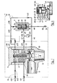
- FIG. 1 serves for a simplified explanation, because in the practical implementation of the valve all control and check valves as well as the lines with the throttling points can be contained within the contour of the valve.
- a valve 1 has a housing 10 and a cover 20 which is fastened tightly to the housing 10 by means of screws, not shown.
- Pressure medium from a pressure medium source flows through an inlet connection 11 of the housing 10 and leaves the valve via an outlet connection 12
- Closure part 13 is movably arranged in the pressure area of the inlet connector 11 and has a conical sealing surface 14 on the side facing the outlet connector 12, which comes to rest on a sealing seat 15 in the housing 10 when the valve 1 is closed.
- the closure part 13 On the side of the closure part 13 facing away from the outlet connection 12, the closure part 13 has a rear seat 16 which, in the completely open position of the closure part 13, bears tightly against a stop surface 17 in the housing 10.
- the housing 10 has a cylinder 2, which extends towards the cover 20 and in which a servo piston 24 is movably arranged.
- the piston 24 is fixedly connected to the closure part 13 by means of a rod 23 and divides the space enclosed by the cylinder 2 into a first piston chamber 21 and a second piston chamber 22.
- the rod 23 penetrates a cylinder base 18 which separates the second piston chamber from the pressure area of the inlet connector 11 separates in each position of the closure part 13. In the bottom 18, not shown, the rod 23 surrounding sealing means are provided.
- a helical compression spring 25 is provided, which is supported between the cover 20 and the bottom of a bore 26 which extends through the piston 24 into the rod 23.
- the pressure in the pressure area of the inlet connection 11 is transmitted to a distribution line 40 connected to the housing 10.
- the distribution line 40 is connected to the first piston chamber 21 by means of a first connecting line 41 and to the second piston chamber 22 by means of a second connecting line 42.
- the first connection line 41 and the second connection Line 42 are connected to each other via a third connecting line 43, which consists of two sections 43a and 43b.
- the first piston chamber 21 is connected to a pressure medium sink, here the atmosphere, via a relief line 44 containing a magnetic control valve 441.
- the relief line 44 has a throttle point 442 between the control valve 441 and the first piston chamber 21.
- the second piston chamber 22 is connected via a relief line 45 to a pressure medium sink, here also the atmosphere.
- the relief line 45 has a solenoid control valve 451.
- the first connecting line 41 contains two magnetic control valves 411 and 413 connected in parallel, which lie between the connection point of the section 43b and the first piston chamber 21. In addition, it contains a throttle point 412, which is arranged between the connection point on the distribution line 40 and that of the section 43b. A throttle point 432 is also located in section 43b.
- the second connecting line 42 has a magnetic control valve 421, which lies between the second piston chamber 22 and the connection point of the section 43a. It also has a check valve 422 which can flow through in the direction of the second piston chamber 22 and is located between the connection points on the section 43 a and on the distribution line 40.
- a double-acting check valve 3 which consists of a housing 31, a closure plate 32 and a spring 33.
- the Housing 31 is connected to section 43b via a bore 34, whereas a bore 35 connected to an external medium line 46 is provided at the other end of this housing.
- the housing 31 also contains a third bore 36, which is made between the two bores 34 and 35 and is connected to the section 43a.
- the spring 33 loads the closure plate 32 in the direction of the bore 35.
- the closure plate 32 On each of the two end faces, the closure plate 32 has a sealing surface which, in one extreme position of the plate, has a sealing seat 37 on the bore 34 and in the other extreme position with a Seal seat 38 cooperate on the bore 35.
- the locking plate 32 which can be moved in the housing 31 between two extreme positions, either shuts off the bore 35, with the bores 34 and 36 communicating with one another (drawn position in FIG. 1), or it shuts off the bore 34, with the bores 35 and 36 communicating with one another .
- the solenoid control valves 441, 411 and 413 are actuated simultaneously by a single control line 51, the solenoid control valve 441 being closed and the solenoid control valves 411 and 413 being open when the line 51 is de-energized.
- the solenoid control valves 451 and 421 are likewise actuated simultaneously by a single control line 52, in that the solenoid control valve 451 is open or the solenoid control valve 421 is closed when the line 52 is de-energized.
- the connecting lines 41 and 42, and the sections 43a and 43b, up to the solenoid control valves 411, 413 and 421 there is approximately the same medium pressure as in the inlet connection 11.
- the foreign medium line 46 is depressurized because a valve 50 in this line shuts off the supply of foreign medium.
- the closure plate 32 is therefore pressed tightly against the sealing seat 38 by the pressure of the medium in the housing 31 and by the spring 33.
- the closing of the valve 1 is either by the operating personnel or automatically by an accident in the System triggered, the current in the control line 51 being turned off. This closes the solenoid control valve 441 and the solenoid control valves 411 and 413 open. In a fraction of a second, which depends on the cross-section of the throttle point 412, pressure medium flows via the lines 40 and 41 into the first piston chamber 21. As a result, the piston 24 together with the rod 23 and the closure part 13 are inserted into the closing, ie Safety position pushed. If the control line 51 is now energized again, the solenoid control valve 441 opens and the solenoid control valves 411 and 413 close, so that the pressure in the first piston chamber 21 drops to atmospheric pressure.
- control line 52 is also energized, so that solenoid control valve 451 closes and solenoid control valve 421 opens. Pressure medium thus enters the second piston chamber 22, whereby movement of the closure part 13 in the opening direction is initiated.
- the control line 52 is de-energized again, so that the solenoid control valve 451 opens and the solenoid control valve 421 closes. This restores the normal operating conditions.
- the throttle point 442 limits the amount of medium flowing out of the first piston chamber 21 per second in order to increase the opening time of the valve 1 and thereby to avoid pressure surges in the pressure lines of the system.
- the throttle point 442 also has the important task of enabling the valve l to be closed and kept closed in the event of failure and even total destruction of the solenoid control valve 441, by pressure build-up in the first piston chamber 21 with constant refilling of pressure medium via the then opened solenoid control valves 411 and 413 allowed.
- valve 1 The functionality of valve 1 is checked in two steps.
- a first step the control line 52 is energized, whereby the solenoid control valve 451 is closed and the solenoid control valve 421 is opened.
- the second piston chamber 22 fills with pressure medium, which forms a pressure cushion.
- the control line 51 is de-energized, whereupon the solenoid control valve 441 closes and the solenoid control valves 411 and 413 open.
- the first piston chamber 21 is now also acted upon by pressure medium, and there is approximately the same pressure in the piston chambers 21 and 22 as in the inlet port 11. The forces acting on the moving parts in terms of pressure are thus largely balanced and only the force of the helical compression spring 25 tries to close valve 1.
- Pressure medium flows from the second piston chamber 22 via the second connecting line 42, the section 43a of the third connecting line 43, the double-acting check valve 3, the throttle point 432 in section 43b and the first connecting line 41 into the first piston chamber 21, the valve 1 closing slowly .
- the closing speed is primarily determined by the amount of pressure medium let through by the throttle point 432 per unit of time.
- the check valve 422 prevents pressure medium from flowing out of the second piston chamber 22 into the distribution line 40.
- the necessary additional quantity for filling the first piston chamber 21 is supplied via the lines 40 and 41 from the pressure area of the inlet connection 11.
- Essential in the test mode are: first, the pre-formation of a pressure cushion in the second piston chamber 22, as a result of which the valve 1 is closed in a controlled manner is much easier, and secondly, the determination of the flow rate from the second piston chamber 22 to the first piston chamber 21 by means of the single throttle point 432, as a result of which the closing time of the valve 1 can be determined very precisely.
- the closing time can be measured in a known manner and possible deviations of the measured value from a target value can provide important information with regard to any defects in the valve 1, such as leaks, contamination or deformations.
- valve 1 If there is no pressure in the pressure area of the inlet connection 11, there is also no pressure in all other lines and spaces of the valve 1.
- the valve 1 is then kept closed by means of the helical compression spring 25 and the closure remains by the spring 33 plate 32 of the double-acting check valve 3 in its normal position shown in FIG. 1, in which the foreign medium line 46 is shut off.
- the valve 1 can then only be opened by introducing foreign medium via the foreign medium line 46.
- the control line 52 is first energized, so that the solenoid control valve 451 closes and the solenoid control valve 421 opens. By opening the valve 50, the foreign medium line 46 is connected to a foreign medium source, not shown.
- the foreign medium pressure acts on the closure plate 32 via the bore 35 and moves it against the action of the spring 33 to the sealing seat 37 at the bore 34.
- the foreign medium now flows through the bore 36, the section 43a, and the second connecting line 42 into the second Piston chamber 22, the piston 24 and thus the closure part 13 being pushed into the open position.
- the closure plate 32 and the check valve 422 prevent foreign medium from entering the section 43b and the lines 41 and 40.
- valve 1 For safety reasons, various redundancies can be provided on valve 1. In the embodiment according to FIG. 1, only the magnets connected in parallel are Control valves 411 and 413 are available as an example of such redundancy because the safety requirements there are particularly high. Depending on requirements and spatial conditions, however, further redundancies can be provided, for example also two parallel helical compression springs 25.
- the invention is implemented in its simplest form, wherein - as in FIG. 1 - the open position of the valve 1 is its working position.
- a foreign medium supply is missing in all four examples.
- FIGS. 3a to 3d correspond in their simplicity to those according to FIGS. 2a to 2d, but they are closed in their working position and the open position is their safety position.
- valves 1 are in their working position. Their functioning results from the description of FIG. 1. Only the examples according to FIGS. 2b, 3c and 3d have a special feature in that they only remain in the working position when the second piston chamber 22 is under pressure. In contrast to the other examples, this means that in the working position of the valve 1 in FIGS. 2b, 3c and 3d, the solenoid control valve 451 must be closed and the solenoid control valve 421 must be open, and that the solenoid control valve 451 must be open during the transition to the safety position and that Solenoid control valve 421 are closed. For this they have to Solenoid control valves 451 and 421 are not actuated during the function test.
- FIGS. 2a to 2d and 3a to 3d thus show the variety of possible applications of the invention when a pressure medium operated valve is to be operated with two different opening or closing times.
- FIG. 4 largely corresponds to the example according to FIG. 2, but a foreign medium line 46 is provided, which is connected to the third connecting line 43 via a check element 47.
- the check element 47 can be flowed through in the direction of the line 43.
- a non-return element 48 is provided in the first connecting line 41, namely upstream of the connection point of the third connecting line 43.
- the non-return element can be flowed through in the direction of the connection point just mentioned.
- normal closing elements can also be used.
- the embodiments according to FIGS. 2b to 2d and FIGS. 3a to 3d can also be provided with a foreign medium supply.
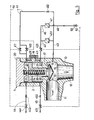
- the two cavity sections are connected to one another via a third connecting line 43, which has two openings on the cylinder side of the control valves 411 and 413 provided in the first connecting line 41 and the control valve 421 provided in the second connecting line 42.
- the third connecting line extends for the most part through the wall of the cylinder 2.
- the one having the throttle point 431 Section of the third connecting line 43 is formed in a wall part 19, which is releasably attached to the outside of the cylinder 2 by means of screws, not shown. This allows the throttle to be replaced easily, either for the purpose of replacement by a throttle of the same size or for the purpose of replacement by a throttle with a larger or smaller passage cross section.
- valve according to FIG. 5 is open, the same conditions are present as have been described for the valve according to FIG. 1. 5 is either triggered by the operating personnel or automatically by a fault in the system, the current in the control line 51 being switched off. This closes the solenoid control valve 441 and the solenoid control valves 411 and 413 open. In a fraction of a second, which is dependent on the cross section of the throttle point 412, pressure medium flows via the lines 40 and 41 into the first piston chamber 21. As a result, the servo piston 24 together with the rod 23 and the closure part 13 are displaced downward, ie in Direction of the closing or safety position.
- the full pressure of the pressure medium in the first piston chamber 21 initially acts on the piston 24, while this pressure is not yet effective in the second piston chamber 22 because of the throttle point 431 in the third connecting line 43.
- the piston 24 thus initially moves relatively rapidly downward, the second piston chamber 22 shrinking and a pressure being established in it, which lies between the pressure in the first piston chamber and the atmospheric pressure. Some pressure medium escapes via the relief line 45.
- pressure medium also penetrates into the second piston chamber 22 via the third connecting line 43, so that the pressure in this piston chamber increases somewhat. This will make the piston Movement is initially easy and then increasingly braked, ie the moving system reaches the lower end position at a constantly decreasing speed.
- the closure part 13 is thus placed on the seat surface 15 without damage to this seat surface or to the sealing surface 14 occurring.
- the braking effect is determined by the dimensioning of the cross sections of the throttle points 431 and 452.
- control line 51 is now energized again, the solenoid control valve 441 opens and the solenoid control valves 411 and 413 close, so that the pressure in the first piston chamber 21 drops to atmospheric pressure.
- control line 52 is also energized, so that solenoid control valve 451 closes and solenoid control valve 421 opens.
- Pressure medium thus enters the second piston chamber 22, whereby movement of the closure part 13 in the opening direction is initiated. With this opening movement, a braking effect of the movable system occurs in the same way as described above for the downward movement.
- control line 52 is de-energized again, so that the solenoid control valve 451 opens and the solenoid control valve 421 closes. This restores the normal operating conditions.
- the throttle point 442 also has the important task of enabling the valve 1 to be closed and kept closed in the event of failure and even total destruction of the solenoid control valve 441, by pressure build-up in the first piston chamber 21 with constant refilling of pressure medium via the then opened solenoid control valves 411 and 413 allowed.
Landscapes
- Engineering & Computer Science (AREA)
- General Engineering & Computer Science (AREA)
- Mechanical Engineering (AREA)
- Safety Valves (AREA)
- Vehicle Body Suspensions (AREA)
Abstract
Das durckmediumbetätigte Ventil (1) weist einen Druckmittel-Eintrittsstutzen (11), einen Austrittsstutzen (12) und einen Zylinder (2) auf, in dem ein mit einem Verschlußteil (13) verbundener Kolben (24) verschiebbar ist. Der Kolben unterteilt den Zylinder (2) in einen ersten Kolbenraum (21) und einen zweiten Kolbenraum (22). Zwei je ein Steuerventil (441, 451) enthaltende Entlastungsleitungen (44, 45) sind an den Kolbenräumen (21, 22) angeschlossen und führen zu einer Druckmittelsenke. Eine ein Steuerventil (411) enthaltende erste Verbindungsleitung (41) führt vom Eintrittsstutzen (11) zum ersten Kolbenraum (21) und eine ein Steuerventil (421) enthaltende zweite Verbindungsleitung (42) führt vom Eintrittsstutzen (11) zum zweiten Kolbenraum (22). Die zweite Verbindungsleitung (42) weist ein in Richtung zum zweiten Kolbenraum (22) durchströmbares Rückschlagventil (422) auf und zwischen der ersten und der zweiten Verbindungsleitung ist eine dritte Verbindungsleitung (43) vorgesehen.The pressure medium-operated valve (1) has a pressure medium inlet connection (11), an outlet connection (12) and a cylinder (2) in which a piston (24) connected to a closure part (13) can be displaced. The piston divides the cylinder (2) into a first piston chamber (21) and a second piston chamber (22). Two relief lines (44, 45) each containing a control valve (441, 451) are connected to the piston chambers (21, 22) and lead to a pressure medium sink. A first connecting line (41) containing a control valve (411) leads from the inlet connection (11) to the first piston chamber (21) and a second connecting line (42) containing a control valve (42) leads from the inlet connection (11) to the second piston chamber (22). The second connecting line (42) has a check valve (422) which can flow through in the direction of the second piston chamber (22), and a third connecting line (43) is provided between the first and the second connecting line.
Hierdurch wird es möglich, den Verschlußteil mit zwei verschiedenen Geschwindigkeiten zu bewegen.
Description
Die Erfindung betrifft ein druckmediumbetätigtes Ventil mit einem Gehäuse, das einen mit einer Druckmittelquelle verbundenen Eintrittsstutzen, einen Austrittsstutzen und einen vom durchströmten Ventilraum abgeschirmten Zylinder aufweist, mit einem im Druckbereich des Eintrittsstutzens angeordneten Verschlussteil, das mittels einer Stange mit einem im Zylinder verschiebbar angeordneten Servo-Kolben verbunden ist, wobei der Kolben den Zylinder in einen beim Uebergang von einer Arbeits- in eine Sicherheitsstellung sich vergrössernden, ersten Kolbenraum und einen beim Uebergang von der Arbeits- in die Sicherheitsstellung sich verkleinernden, zweiten Kolbenraum unterteilt, mit mindestens einer im Zylinder angeordneten Feder, die den Kolben mit der Stange und dem Verschlussteil in Richtung auf die Sicherheitsstellung des Ventils belastet, mit zwei je ein Steuerventil enthaltenden Entlastungsleitungen, die an den beiden Kolbenräumen angeschlossen sind und zu mindestens einer Druckmittelsenke, vorzugsweise der Atmosphäre führen, mit einer ein Steuerventil enthaltenden ersten Verbindungsleitung zwischen dem Druckbereich des Eintrittsstutzens und dem ersten Kolbenraum und mit einer ein Steuerventil enthaltenden zweiten Verbindungsleitung zwischen dem Druckbereich des Eintrittsstutzens und dem zweiten Kolbenraum.The invention relates to a pressure medium-operated valve with a housing, which has an inlet connection connected to a pressure medium source, an outlet connection and a cylinder shielded from the flow through the valve space, with a closure part arranged in the pressure region of the inlet connection, which is connected by means of a rod with a servo which is arranged displaceably in the cylinder. Piston is connected, the piston dividing the cylinder into a first piston chamber, which increases in the transition from a working position to a safety position, and a second piston chamber, which decreases in the transition from the working position to the safety position, with at least one spring arranged in the cylinder , which loads the piston with the rod and the closure part in the direction of the safety position of the valve, with two relief lines each containing a control valve, which on the two piston chambers are connected and lead to at least one pressure medium sink, preferably the atmosphere, with a first connecting line containing a control valve between the pressure area of the inlet connector and the first piston chamber and with a second connecting line containing a control valve between the pressure area of the inlet connector and the second piston chamber.
Es ist ein solches Ventil bekannt, dessen Verschlussteil durch Oeffnen und Schliessen der Steuerventile in den Verbindungs- bzw. Entlastungsleitungen bewegbar ist, wobei die Schliess- und die Oeffnungszeit des Verschlussteils konstant sind und von den Auslegungsgrössen des Ventils, inbesondere von den Druckverhältnissen und von den Ventilabmessungen, abhängen. Das bedeutet, dass eine Aenderung der Schliess- und der Oeffnungszeit nicht ohne weiteres möglich ist, was noch dadurch unterstützt wird, dass die Steuerventile meistens als einfache, ferngesteuerte Magnetventile ausgebildet sind, die zwar zuverlässig, robust und kostengünstig sind, jedoch nur die beiden Stellungen "offen" und "geschlossen" einnehmen können; eine einfache Verstellung des Oeffnungsquerschnitts erlauben sie nicht. In bezug auf den normalen Betrieb des Ventils ist dieser Sachverhalt aber befriedigend und gewährleistet im voraus berechenbare Betriebsverhältnisse.Such a valve is known, the closure part of which can be moved in the connecting or relief lines by opening and closing the control valves, the closing and opening times of the closure part being constant and of the design parameters of the valve, in particular of the pressure conditions and of the Valve dimensions, depend. This means that the closing and opening times cannot be changed easily, which is further supported by the fact that the control valves are mostly designed as simple, remote-controlled solenoid valves that are reliable, robust and inexpensive, but only the two positions can take "open" and "closed"; they do not permit simple adjustment of the opening cross section. With regard to the normal operation of the valve, however, this is satisfactory and guarantees predictable operating conditions.
Oft tritt aber der Fall auf, dass ein als Sicherheitsventil eingesetztes Ventil mit einer gewissen Häufigkeit, im Hinblick auf besondere Anforderungen an die Betriebssicherheit, auf seine Funktionstüchtigkeit hin geprüft werden muss. Die häufige Betätigung solcher Ventile zu Prüfzwecken unter den bei normalem Betrieb herrschenden Bedingungen beansprucht wegen des abrupten Schliessvorganges die Sitzflächen im Ventil sehr stark, so dass eine Vergrösserung der Gefahr von Undichtheiten und damit eine erhebliche Verkürzung der Lebensdauer des Ventils durch rasche Abnützung der Sitzflächen eintreten kann. Dazu kommt eine verstärkte Beanspruchung der am Ventil angeschlossenen Druckleitung durch die häufigen Druckstösse infolge des abrupten Schliessvorganges.Often, however, the case arises that a valve used as a safety valve has to be checked for its functionality with a certain frequency with regard to special requirements for operational safety. The frequent actuation of such valves for testing purposes under the conditions prevailing during normal operation places a heavy load on the seat surfaces in the valve due to the abrupt closing process, so that an increase in the risk of leaks and thus a considerable reduction in the service life of the valve can occur through rapid wear of the seat surfaces. In addition, there is an increased stress on the pressure line connected to the valve due to the frequent pressure surges as a result of the abrupt closing process.
Um diese Erscheinungen zu vermeiden, wurde die Möglichkeit erwogen, beim Prüfen oder Testen des Ventils den Verschlussteil langsam in die Sicherheitsstellung zu bewegen. Das Ventil sollte also je nach Bedarf sowohl schnell als auch langsam in die Sicherheitsstellung gebracht werden können. Eine Möglichkeit, dies zu erreichen, besteht darin, mindestens ein zweites, zu dem bereits vorhandenen Steuerventil parallelgeschaltetes Steuerventil in der Entlastungsleitung des zweiten Kolbenraumes und/oder in der ersten Verbindungsleitung vorzusehen, wobei das zusätzliche Steuerventil einen kleineren Durchströmquerschnitt als das schon vorhandene Steuerventil aufweist. Somit kann wahlweise das Steuerventil mit dem grösseren Durchströmquerschnitt für den Normalbetrieb und das Steuerventil mit dem kleineren Durchströmquerschnitt für die Funktionsprüfung betätigt werden.In order to avoid these phenomena, the possibility was considered to slowly move the closure part into the safety position when checking or testing the valve. The valve should therefore be able to be moved into the safety position both quickly and slowly as required. One way to achieve this is to provide at least one second control valve, which is connected in parallel with the already existing control valve, in the relief line of the second piston chamber and / or in the first connecting line, the additional control valve having a smaller flow cross-section than the already existing control valve. Thus, the control valve with the larger flow cross-section for normal operation and the control valve with the smaller flow cross-section can optionally be operated for the function test.
Eine solche Lösung ist aber in der Praxis meistens nicht anwendbar, weil dort, wo die Sicherheitserfordernisse besonders hoch sind, aus Redundanzgründen die Steuerventile zweifach oder eventuell sogar mehrfach parallel und/oder in Serie geschaltet angeordnet werden. In solchen Fällen scheitert die Unterbringung eines zusätzlichen Steuerventils samt Steuerleitung am Platzmangel. Hinzu kommen - bedingt durch jedes zusätzliche Steuerventil - noch die Erhöhung des Störfallrisikos und die allgemeine Verkomplizierung der ganzen Ventilsteuerung.However, such a solution is usually not applicable in practice, because where the safety requirements are particularly high, the control valves are arranged in parallel and / or in series for two or even several times for redundancy reasons. In such cases, the accommodation of an additional control valve including the control line fails due to lack of space. In addition - due to each additional control valve - there is an increase in the risk of accidents and the general complication of the entire valve control.
Es ist Aufgabe der Erfindung, ein druckmediumbetätigtes Ventil der eingangs genannten Art zu schaffen, das auf einfache, sichere und kostengünstige Weise nach Bedarf mit zwei verschiedenen Geschwindigkeiten in die Sicherheitsstellung gebracht werden kann.It is an object of the invention to provide a pressure medium-actuated valve of the type mentioned at the outset, which can be brought into the safety position in a simple, safe and cost-effective manner at two different speeds as required.
Diese Aufgabe wird erfindungsgemäss dadurch gelöst, dass die zweite Verbindungsleitung ein in Richtung zum zweiten Kolbenraum durchströmbares Rückschlagventil aufweist und dass eine dritte Verbindungsleitung vorgesehen ist, die einen ersten Hohlraumabschnitt mit einem zweiten Hohlraumabschnitt verbindet, wobei der erste Hohlraumabschnitt sich über das Innere der ersten Verbindungsleitung, den ersten Kolbenraum und das Innere der an diesem Raum angeschlossenen Entlastungsleitung bis zum zylinderseitigen Ende des in dieser Entlastungsleitung befindlichen Steuerventils erstreckt und der zweite Hohlraumabschnitt vom zylinderseitigen Ende des Rückschlagventils in der zweiten Verbindungsleitung über den zweiten Kolbenraum bis zum zylinderseitigen Ende des Steuerventils in der an den zweiten Kolbenraum angeschlossenen Entlastungsleitung reicht.According to the invention, this object is achieved in that the second connecting line has a non-return valve through which flow can be made in the direction of the second piston chamber, and in that a third connecting line is provided which connects a first cavity section to a second cavity section, the first cavity section extending over the interior of the first connecting line, extends the first piston chamber and the interior of the relief line connected to this space to the cylinder-side end of the control valve located in this relief line and the second cavity section from the cylinder-side end of the check valve in the second connecting line via the second piston chamber to the cylinder-side end of the control valve in the to discharge line connected to the second piston chamber is sufficient.
Hierdurch wird es möglich, im Normalbetrieb des Ventils dessen Verschlussteil - wie bisher - mit der gewünschten hohen Geschwindigkeit, beim Prüf- oder Testbetrieb jedoch mit kleinerer Geschwindigkeit zu bewegen, so die dass im letztgenannten Fall Ventilsitzflächen geschont werden. Damit ist auch bei häufigem Testbetrieb die Gefahr von Undichtheiten des Ventils eliminiert und dessen Lebensdauer erhöht. Besonders vorteilhaft ist dabei, däss dies auf konstruktiv einfache Weise erreicht wird, weil keine zusätzlichen Steuerventile notwendig sind. Die dritte Verbindungsleitung kann zwischen der ersten und der zweiten Verbindungsleitung oder zwischen den beiden Entlastungsleitungen angebracht sein oder auch in einer die beiden Kolbenräume verbindenden Bohrung in Kolben bestehen, so dass für den Konstrukteur eine grosse Freiheit bei der Gestaltung des Ventils besteht. Ein weiterer Vorteil ist darin zu sehen, dass sich das Verhalten des Ventils beim Testbetrieb vorausberechnen lässt.This makes it possible in normal operation of the valve to move its closure part - as before - at the desired high speed, but in test or test mode at a lower speed, so that in the latter case valve seat surfaces are protected. This eliminates the risk of leaks in the valve and increases its service life even during frequent test operation. It is particularly advantageous that this is achieved in a structurally simple manner because no additional control valves are necessary. The third connection line can be between the first and the second connection line or between be attached to the two relief lines or also exist in a bore in the piston connecting the two piston chambers, so that the designer has great freedom in the design of the valve. Another advantage is that the behavior of the valve during test operation can be calculated in advance.
Die Zusammenschaltung der Steuerventile nach Anspruch 2 ist sowohl im Normal- wie im Testbetrieb anwendbar und erlaubt für beide Betriebsarten ein gleichzeitiges Betätigen von jeweils zwei Steuerventilen mit einer einzigen Steuerleitung. Zusätzlich reduziert die paarweise Zusammenschaltung der Steuerventile die Fehlermöglichkeiten beim Betätigen des Ventils.The interconnection of the control valves according to
Die Ausführungsform nach Anspruch 3 ermöglicht es, bei Drucklosigkeit im Druckmediumsystem, das Verschlussteil des Ventils mit Hilfe von Fremdmedium in die Arbeitsstellung zu bewegen. Eine besonders einfache, sichere und kostengünstige Zufuhr von Fremdmedium lässt sich nach dem Merkmal des Anspruchs 4 verwirklichen, während die Vorbelastung gemäss dem Anspruch 5 das Verhalten der Fremdmediumzufuhr im drucklosen Zustand des Ventils eindeutig festlegt, so dass unerwünschte Stellungen des Verschlussteils des doppeltwirkenden Rückschlagventils vermieden werden.The embodiment according to
Die Steuerventilanordnung nach Anspruch 6 sichert die Kolbenräume gegen jegliche unerwünschte Beaufschlagung durch Druckmedien, womit eine besonders präzise Steuerung des Ventils, auch während der Funktionsprüfung, möglich wird. Mit präziser Steuerung oder Steuerungsgenauigkeit ist die Grösse des Streubereichs gemeint, innerhalb dem die Schliess- und Oeffnungszeiten variieren können. Die Einhaltung von sehr kleinen Streubereichen ist deswegen sehr wichtig, weil aus eventuellen Abweichungen von der normalen Schliesszeit wichtige Schlüsse über die Reibungs- und Dichtheitsverhältnisse innerhalb des Ventils gezogen werden können.The control valve arrangement according to claim 6 secures the piston chambers against any undesired exposure to pressure media, which enables a particularly precise control of the valve, even during the functional test. By precise control or control accuracy is meant the size of the spreading area within which the closing and opening times vary can. It is very important to adhere to very small scattering ranges, because important deviations from the normal closing time can be drawn from the friction and tightness conditions within the valve.
Die Steuerungsgenauigkeit wird durch das Merkmal nach Anspruch 7 nochmals erhöht, indem die Drosselstelle in der ersten Verbindungsleitung eine bessere Vorausberechnung und Eichung der hindurchfliessenden Druckmediummenge erlaubt.The control accuracy is further increased by the feature according to claim 7, in that the throttle point in the first connecting line allows a better pre-calculation and calibration of the quantity of pressure medium flowing through.
Durch die Anordnung gemäss Anspruch 8 wird der Druckmediumfluss im Testbetrieb unabhängig von dem für den Normalbetrieb optimierten Druckmediumfluss durch die Drosselstelle in der ersten Verbindungsleitung gemacht. Dank der Drosselstelle in der dritten Verbindungsleitung gemäss Anspruch 9 kann der für den Testbetrieb nötige Druckmediumfluss sehr genau vorausberechnet und geeicht werden, so dass die nötige Zeit zum Uebergang in die Sicherheitsstellung des Verschlussteils im Prüfbetrieb mit sehr hoher Genauigkeit im voraus bestimmt werden kann.The arrangement according to claim 8 makes the pressure medium flow in test mode independent of the pressure medium flow optimized for normal operation through the throttle point in the first connecting line. Thanks to the throttle point in the third connecting line, the pressure medium flow required for the test operation can be calculated very precisely in advance and verified, so that the time required for the transition to the safety position of the closure part in the test operation can be determined in advance with very high accuracy.
Durch das Merkmal des Anspruchs 10 wird der aus dem ersten Kolbenraum austretende Druckmediumfluss beim Uebergang des Ventils in die Arbeitsstellung rechnerisch besser erfassbarund die Eichbarkeit des in der Entlastungsleitung fliessenden Mediumstromes wird gesteigert. Damit wird das Verhalten des Ventils während des Uebergangs in die Arbeitsstellung - sowohl im Prüf- wie im Normalbetrieb - besser beherrschbar. Ein zusätzlicher Vorteil ergibt sich noch dadurch, dass bei der Wahl einer genügend starken Drosselung es möglich wird, das Ventil durch ständige Zufuhr von Druckmittel in der Sicherheitsstellung zu halten, selbst im Falle eines Versagens oder eines Abreissens des Steuerventils in der betreffenden Entlastungsleitung.Due to the feature of
Um zu vermeiden, dass das aus dem Servokolben, der Stange und dem Verschlussteil bestehende bewegliche System mit zu grosser Geschwindigkeit in den beiden Endstellungen auf die zugehörige Gegenfläche auftritt, ist gemäss Anspruch 11 die am ersten und am zweiten Hohlraumabschnitt angeschlossene dritte Verbindungsleitung zylinderseitig des in der ersten Verbindungsleitung befindlichen Steuerventils und des in der zweiten Verbindungsleitung befindlichen Steuerventils mit dem betreffenden Hohlraumabschnitt verbunden. Hierdurch wird es möglich, den Verschlussteil bei seiner Bewegung in die beiden Entstellungen zu bremsen, so dass das bewegliche System mit genügend niedriger Geschwindigkeit, d.h. ohne Beschädigungen zu verursachen, auf die zugehörige Gegenfläche auftritt. Von besonderem Vorteil ist, dass die Bremswirkung erreicht wird, ohne dass zusätzliche bewegliche Teile, also z.B. Ventile, benötigt werden.In order to avoid that the movable system consisting of the servo piston, the rod and the closure part occurs at too high a speed in the two end positions on the associated counter surface, the third connecting line connected to the first and second cavity section is on the cylinder side of the in the first control line located control valve and the control valve located in the second connection line connected to the cavity section in question. This makes it possible to brake the locking part as it moves into the two disfigurements, so that the movable system is moving at a sufficiently low speed, i.e. without causing damage to the associated counter surface. It is particularly advantageous that the braking effect is achieved without additional moving parts, e.g. Valves.
Einige Ausführungsbeispiele der Erfindung sind in der folgenden Beschreibung anhand der Zeichnung näher erläutert. Es zeigen in schematischer Form:
- Fig. 1 ein druckmediumbetätigtes Ventil nach der Erfindung, im Schnitt,
- Fig. 2a bis d vier gegenüber Fig. 1 vereinfachte Ausführungsformen des erfindungsgemässen Ventils,
- Fig. 3a bis d vier Ausführungsformen des erfindungsgemässen Ventils, bei denen die Arbeitsstellung gleich der Schliesstellung ist,
- Fig. 4 eine gegenüber Fig. 2a abgewandelte Ausführungsform und
- Fig. 5 eine weitere Ausführungsform.
- 1 is a pressure medium operated valve according to the invention, in section,
- 2a to d four compared to Fig. 1 simplified embodiments of the valve according to the invention,
- 3a to d four embodiments of the valve according to the invention, in which the work position is equal to the closed position,
- Fig. 4 shows a modified embodiment compared to Fig. 2a and
- Fig. 5 shows another embodiment.
Die in Fig. 1 gewählte Darstellung dient zur vereinfachten Erläuterung, denn bei der praktischen Ausführung des Ventils können alle Steuer- und Rückschlagventile sowie die Leitungen mit den Drosselstellen innerhalb der Kontur des Ventils enthalten sein.The illustration chosen in FIG. 1 serves for a simplified explanation, because in the practical implementation of the valve all control and check valves as well as the lines with the throttling points can be contained within the contour of the valve.
Nach Fig. 1 weist ein Ventil 1 ein Gehäuse 10 und einen Deckel 20 auf, der mittels nicht gezeichneter Schrauben am Gehäuse 10 dicht befestigt ist. Druckmedium aus einer nicht gezeigten Druckmittelquelle strömt über einen Eintrittsstutzen 11 des Gehäuses 10 diesem zu und verlässt das Ventil über einen Austrittsstutzen 12. Ein Verschlussteil 13 ist bewegbar im Druckbereich des Eintrittsstutzens 11 angeordnet und weist auf der dem Austrittsstutzen 12 zugewandten Seite eine konisch ausgebildete Dichtfläche 14 auf, die beim Schliessen des Ventils 1 auf einen Dichtsitz 15 im Gehäuse 10 zu liegen kommt. Auf der dem Austrittsstutzen 12 abgewandten Seite des Verschlussteils 13 weist dieser einen Rücksitz 16 auf, der in der ganz offenen Stellung des Verschlussteils 13 an einer Anschlagfläche 17 im Gehäuse 10 dicht anliegt.1, a
Das Gehäuse 10 weist einen Zylinder 2 auf, der sich gegen den Deckel 20 hin erstreckt und in dem ein Servo-Kolben 24 bewegbar angeordnet ist. Der Kolben 24 ist mittels einer Stange 23 mit dem Verschlussteil 13 fest verbunden und unterteilt den vom Zylinder 2 umschlossenen Raum in einen ersten Kolbenraum 21 und einen zweiten Kolbenraum 22. Die Stange 23 durchstösst einen Zylinderboden 18, der den zweiten Kolbenraum vom Druckbereich des Eintrittsstutzens 11 in jeder Stellung des Verschlussteils 13 trennt. Im Boden 18 sind nicht gezeichnete, die Stange 23 umgebende Dichtungsmittel vorgesehen.The
Im ersten Kolbenraum 21 ist eine Schraubendruckfeder 25 vorgesehen, die sich zwischen dem Deckel 20 und dem Boden einer Bohrung 26 abstützt, die durch den Kolben 24 hindurch bis in die Stange 23 hineinreicht.In the
Der Druck im Druckbereich des Eintrittsstutzens 11 wird auf eine am Gehäuse 10 angeschlossene Verteilleitung 40 übertragen. Die Verteilleitung 40 ist mittels einer ersten Verbindungsleitung 41 mit dem ersten Kolbenraum 21 und mittels einer zweiten Verbindungsleitung 42 mit dem zweiten Kolbenraum 22 verbunden. Die erste Verbindungsleitung 41 und die zweite Verbindungsleitung 42 sind über eine dritte Verbindungsleitung 43 miteinander verbunden, die aus zwei Abschnitten 43a und 43b besteht.The pressure in the pressure area of the
Ueber eine ein Magnetsteuerventil 441 enthaltende Entlastungsleitung 44 ist der erste Kolbenraum 21 mit einer Druckmittelsenke, hier der Atmosphäre, verbunden. Zwischen dem Steuerventil 441 und dem ersten Kolbenraum 21 weist die Entlastungsleitung 44 eine Drosselstelle 442 auf. Der zweite Kolbenraum 22 ist über eine Entlastungsleitung 45 mit einer Druckmittelsenke, hier ebenfalls der Atmosphäre, verbunden. Die Entlastungsleitung 45 weist ein Magnetsteuerventil 451 auf.The
Die erste Verbindungsleitung 41 enthält zwei parallelgeschaltete Magnetsteuerventile 411 und 413, die zwischen der Anschlussstelle des Abschnitts 43b und dem ersten Kolbenraum 21 liegen. Ausserdem enthält sie eine Drosselstelle 412, die zwischen der Anschlussstelle an der Verteilleitung 40 und derjenigen des Abschnitts 43b angeordnet ist. Eine Drosselstelle 432 befindet sich auch im Abschnitt 43b.The first connecting
Die zweite Verbindungsleitung 42 weist ein Magnetsteuerventil 421 auf, das zwischen dem zweiten Kolbenraum 22 und der Anschlussstelle des Abschnitts 43a liegt. Sie weist ferner ein in Richtung zum zweiten Kolbenraum 22 durchströmbares Rückschlagventil 422 auf, das sich zwischen den Anschlussstellen am Abschnitt 43a und an der Verteilleitung 40 befindet.The second connecting
Zwischen den Abschnitten 43a und 43b der dritten Verbindungsleitung ist ein doppeltwirkendes Rückschlagventil 3 vorgesehen, das aus einem Gehäuse 31, einem Verschlussteller 32 und einer Feder 33 besteht. Das Gehäuse 31 ist über eine Bohrung 34 mit dem Abschnitt 43b verbunden, wogegen am anderen Ende dieses Gehäuses eine mit einer Fremdmediumleitung 46 verbundene Bohrung 35 vorgesehen ist. Das Gehäuse 31 enthält noch eine dritte Bohrung 36, die zwischen den beiden Bohrungen 34 und 35 angebracht ist und mit dem Abschnitt 43a verbunden ist. Die Feder 33 belastet den Verschlussteller 32 in Richtung auf die Bohrung 35. Auf jeder der beiden Stirnseiten weist.der Verschlussteller 32 eine Dichtfläche auf, die in der einen Extremstellung des Tellers mit einem Dichtsitz 37 an der Bohrung 34 und in der anderen Extremstellung mit einem Dichtsitz 38 an der Bohrung 35 zusammenwirken. Der im Gehäuse 31 zwischen zwei Extremstellungen bewegbare Verschlussteller 32 sperrt entweder die Bohrung 35 ab, wobei die Bohrungen 34 und 36 miteinander kommunizieren (gezeichnete Stellung in Fig. 1), oder er sperrt die Bohrung 34 ab, wobei die Bohrungen 35 und 36 miteinander kommunizieren.Between the
Die Magnetsteuerventile 441, 411 und 413 werden gleichzeitig durch eine einzige Steuerleitung 51 betätigt, wobei bei stromloser Leitung 51 das Magnetsteuerventil 441 geschlossen ist und die Magnetsteuerventile 411 und 413 offen sind. Die Magnetsteuerventile 451 und 421 werden ebenfalls durch eine einzige Steuerleitung 52 simultan betätigt, indem bei stromloser Leitung 52 das Magnetsteuerventil 451 offen bzw. das Magnetsteuerventil 421 geschlossen ist.The
Das beschriebene Ventil funktioniert wie folgt:
- Bei offenem Ventil l strömt aus der Druckmittelquelle, z.B. einem Dampferzeuger, Druckmedium
über den Eintrittsstutzen 11 indas Gehäuse 10 und verlässt dieses überden Austrittsstutzen 12. Im Normalbetrieb stehen dieMagnetsteuerventile Steuerleitung 51 unter Strom, so dassdas Magnetsteuerventil 441 offen ist und dieMagnetsteuerventile 411 undDie Steuerleitung 52 ist dagegen im Normalbetrieb stromlos und somit sinddas Magnetsteuerventil 451 offen unddas Magnetsteuerventil 421 geschlossen.Der erste Kolbenraum 21 ist dabei überdas offene Magnetsteuerventil 441, dieDrosselstelle 442 und dieEntlastungsleitung 44 mit der Atmosphäre verbunden, ebenso wie der zweite Kolbenraum 22 wegen des offenen Magnetsteuerventils 451 inder Entlastungsleitung 45. Infolgedessen wirkt keine Druckdifferenz aufden Kolben 24; die resultierende Kraft aus dem Produkt aus dem atmosphärischen Druck mal die unterschiedlichen Kolbenoberflächen inden beiden Kolbenräumen 21 und 22 ist vernachlässigbar klein. Demgegenüber ist die resultierende Kraft aus dem Produkt aus dem Mediumdruck mal die Differenz der beiden Stirnflächen des Verschlussteils 13 gross genug, um den Verschlussteil gegen die Kraft der Schraubendruckfeder 25 in Offenstellung zu halten, wobei der Rücksitz 16 gegen dieAnschlagfläche 17 dicht angepresst wird.
- When the
valve 1 is open, pressure medium flows from the pressure medium source, for example a steam generator, via theinlet connector 11 into thehousing 10 and leaves it via theoutlet connector 12. In normal operation, thesolenoid control valves Line 51 is energized so that thesolenoid control valve 441 is open and thesolenoid control valves control line 52 is de-energized in normal operation, and thus thesolenoid control valve 451 is open and thesolenoid control valve 421 is closed. Thefirst piston chamber 21 is connected to the atmosphere via the opensolenoid control valve 441, thethrottle point 442 and therelief line 44, as is thesecond piston chamber 22 due to the opensolenoid control valve 451 in therelief line 45. As a result, no pressure difference acts on thepiston 24; the resulting force from the product of the atmospheric pressure times the different piston surfaces in the twopiston chambers closure part 13 is large enough to hold the closure part against the force of thehelical compression spring 25 in the open position, therear seat 16 being pressed tightly against thestop surface 17.
In der Verteilleitung 40, den Verbindungsleitungen 41 und 42, sowie den Abschnitten 43a und 43b herrscht bis zu den Magnetsteuerventilen 411, 413 und 421 hin annähernd der gleiche Mediumdruck wie im Eintrittsstutzen 11. Die Fremdmediumleitung 46 ist drucklos, weil ein Ventil 50 in dieser Leitung die Zufuhr von Fremdmedium absperrt. Im doppeltwirkenden Rückschlagventil 3 wird deshalb der Verschlussteller 32 vom Druck des Mediums im Gehäuse 31 und von der Feder 33 dicht auf den Dichtsitz 38 gepresst.In the
Das Schliessen des Ventils 1 wird entweder vom Betriebspersonal oder automatisch durch einen Störfall in der Anlage ausgelöst, wobei der Strom in der Steuerleitung 51 abgeschaltet wird. Dadurch schliesst das Magnetsteuerventil 441, und die Magnetsteuerventile 411 und 413 öffnen. In einem Bruchteil von einer Sekunde, der vom Querschnitt der Drosselstelle 412 abhängig ist, strömt Druckmedium über die Leitungen 40 und 41 in den ersten Kolbenraum 21. Dadurch wird der Kolben 24 zusammen mit der Stange 23 und dem Verschlussteil 13 in die Schliess-, d.h. Sicherheitsstellung geschoben. Wird nun die Steuerleitung 51 wieder unter Strom gesetzt, so öffnet das Magnetsteuerventil 441, und es schliessen die Magnetsteuerventile 411 und 413, so dass der Druck im ersten Kolbenraum 21 auf Atmosphärendruck sinkt. Gleichzeitig mit der Stromzufuhr zur Leitung 51 wird auch die Steuerleitung 52 unter Strom gesetzt, so dass das Magnetsteuerventil 451 schliesst und das Magnetsteuerventil 421 öffnet. Damit gelangt Druckmedium in den zweiten Kolbenraum 22, wodurch eine Bewegung des Verschlussteils 13 in Oeffnungsrichtung eingeleitet wird. Nach Erreichen der Offenstellung wird die Steuerleitung 52 wieder stromlos, sodass das Magnetsteuerventil 451 öffnet und das Magnetsteuerventil 421 schliesst. Damit sind die Normalbetriebsbedingungen wieder hergestellt. Durch die Drosselstelle 442 wird die je Sekunde aus dem ersten Kolbenraum 21 ausströmende Mediummenge begrenzt, um die Oeffnungszeit des Ventils 1 zu vergrössern und dadurch Druckstösse in den Druckleitungen der Anlage zu vermeiden. Die Drosselstelle 442 hat ferner die wichtige Aufgabe, bei Ausfall und sogar totaler Zerstörung des Magnetsteuerventils 441, das Schliessen und Geschlossenhalten des Ventils l zu ermöglichen, indem sie eine Druckstauung im ersten Kolbenraum 21 unter ständiger Nachfüllung von Druckmedium über die dann geöffneten Magnetsteuerventile 411 und 413 gestattet.The closing of the
Die Funktionstüchtigkeit des Ventils 1 wird in zwei Schritten geprüft. In einem ersten Schritt wird die Steuerleitung 52 unter Strom gesetzt, womit das Magnetsteuerventil 451 geschlossen und das Magnetsteuerventil 421 geöffnet wird. In der Folge füllt sich der zweite Kolbenraum 22 mit Druckmedium, das ein Druckpolster bildet. In einem zweiten Schritt wird die Steuerleitung 51 stromlos gemacht, woraufhin das Magnetsteuerventil 441 schliesst und die Magnetsteuerventile 411 und 413 öffnen. Der erste Kolbenraum 21 ist jetzt auch von Druckmedium beaufschlagt, und es herrscht in den Kolbenräumen 21 und 22 annähernd der gleiche Druck wie im Eintrittsstutzen 11. Die vom Druck her auf die beweglichen Teile wirkenden Kräfte sind somit weitgehend ausgeglichen und allein die Kraft der Schraubendruckfeder 25 versucht, das Ventil 1 zu schliessen. Dabei fliesst Druckmedium aus dem zweiten Kolbenraum 22 über die zweite Verbindungsleitung 42, den Abschnitt 43a der dritten Verbindungsleitung 43, das doppeltwirkende Rückschlagventil 3, die Drosselstelle 432 im Abschnitt 43b und die erste Verbindungsleitung 41 in den ersten Kolbenraum 21, wobei das Ventil 1 langsam schliesst. Die Schliessgeschwindigkeit ist vor allem durch die von der Drosselstelle 432 durchgelassene Druckmittelmenge je Zeiteinheit bestimmt. Ein Ausfliessen von Druck--medium aus dem zweiten Kolbenraum 22 in die Verteilleitung 40 wird durch das Rückschlagventil 422 verhindert. Bei inkompressiblen Druckmedien wird die nötige Zusatzmenge zum Füllen des ersten Kolbenraums 21 über die Leitungen 40 und 41 aus dem Druckbereich des Eintrittsstutzens 11 zugeführt.The functionality of
Wesentlich beim Testbetrieb sind: erstens, die Vorausbildung eines Druckpolsters im zweiten Kolbenraum 22, wodurch ein kontrolliertes Schliessen des Ventils 1 wesentlich erleichtert wird, und zweitens die Festlegung der Durchflussmenge aus dem zweiten Kolbenraum 22 zum ersten Kolbenraum 21 mittels der einzigen Drosselstelle 432, wodurch die Schliesszeit des Ventils 1 sehr genau festgelegt werden kann. Die Schliesszeit kann auf bekannte Weise gemessen werden und eventuelle Abweichungen des Messwertes von einem Sollwert können wichtige Informationen in bezug auf etwaige Defekte im Ventil 1 liefern, wie z.B. Undichtheiten, Verschmutzungen oder Deformationen.Essential in the test mode are: first, the pre-formation of a pressure cushion in the
Eine Berührung der Dichtfläche 14 des Verschlussteils 13 mit dem Dichtsitz 15 kann während des Testbetriebes vermieden werden, indem kurz vor Erreichen der Schliessstellung - unter Berücksichtigung der Trägheit des beweglichen Systems - Strom in die Steuerleitung 51 eingespiesen wird. Dadurch wird das Magnetsteuerventil 441 geöffnet und die Magnetsteuerventile 411 und 413 geschlossen, so dass der Druck im ersten Kolbenraum 21 auf Atmosphärendruck sinkt und das Verschlussteil 13 noch knapp vor einer Berührung des Dichtsitzes 15 seine Bewegungsrichtung umkehrt, so dass das Ventil 1 öffnet. Dadurch werden frühzeitige Abnützungsschäden an den Dichtflächen vollständig vermieden. Zur völligen Wiederherstellung des Normalbetriebes wird nun die Stromzufuhr zur Steuerleitung 52 unterbrochen, wodurch das Magnetsteuerventil 451 öffnet und das Magnetsteuerventil 421 schliessen. Der Druck im zweiten Kolbenraum 22 gleicht sich dann ebenfalls dem Atmosphärendruck an.Touching the sealing
Bei Drucklosigkeit im Druckbereich des Eintrittsstutzens 11 herrscht in allen übrigen Leitungen und Räumen des Ventils 1 ebenfalls Drucklosigkeit. Mittels der Schraubendruckfeder 25 wird dann das Ventil 1 geschlossen gehalten, und durch die Feder 33 verharrt der Verschlussteller 32 des doppeltwirkenden Rückschlagventils 3 in seiner in Fig. 1 gezeichneten, normalen Stellung, in der die Fremdmediumleitung 46 abgesperrt ist. Das Ventil 1 kann dann nur durch Einführen von Fremdmedium über der Fremdmediumleitung 46 geöffnet werden. Zu diesem Zweck wird zuerst die Steuerleitung 52 unter Strom gesetzt, so dass das Magnetsteuerventil 451 schliesst und das Magnetsteuerventil 421 öffnet. Durch Oeffnen des Ventils 50 wird die Fremdmediumleitung 46 an eine nicht gezeigte Fremdmediumquelle angeschlossen. Der Fremdmediumdruck wirkt über die Bohrung 35 auf den Verschlussteller 32 und verschiebt diesen gegen die Wirkung der Feder 33 bis zum Dichtsitz 37 bei der Bohrung 34. Das Fremdmedium fliesst nun über die Bohrung 36, den Abschnitt 43a, und die zweite Verbindungsleitung 42 in den zweiten Kolbenraum 22, wobei der Kolben 24 und damit der Verschlussteil 13 in die Oeffenstellung geschoben werden. Der Verschlussteller 32 und das Rückschlagventil 422 verhindern dabei ein Eindringen von Fremdmedium in den Abschnitt 43b und die Leitungen 41 und 40. Das Schliessen des Ventils 50 und/oder die Zufuhr von Druckmedium aus dem Eintrittsstutzen 11 mit einem höheren Druck als dem des Fremdmediums zusammen mit einem Unterbrechen der Stromzufuhr zur Steuerleitung 52, stellt den Normalbetrieb wieder her.If there is no pressure in the pressure area of the
Es können auch mehr als eine Fremdmediumquelle wahlweise an die Fremdmediumleitung 46 oder über je eine eigene Fremdmediumleitung mit einem doppeltwirkenden Rückschlagventil an die dritte Verbindungsleitung angeschlossen werden.It is also possible to connect more than one external medium source either to the external
Aus Sicherheitsgründen können verschiedene Redundanzen am Ventil 1 vorgesehen werden. In der Ausführungsform nach Fig. l sind nur die parallelgeschalteten Magnetsteuerventile 411 und 413 als Beispiel einer solchen Redundanz vorhanden, weil dort die Sicherheitsanforderungen besonders gross sind. Je nach Bedarf und Raumverhältnissen können aber weitere Redundanzen vorgesehen werden, z.B. auch zwei parallele Schraubendruckfedern 25.For safety reasons, various redundancies can be provided on
Es ist ebenfalls möglich, in besonderen Fällen eine Drosselstelle auch in die Entlastungsleitung 45 des zweiten Kolbenraumes 22 einzubauen, um die Steuerungsgenauigkeit des Ventils noch zu verfeinern.It is also possible in special cases to also install a throttle point in the
Bei den Ausführungsbeispielen nach Fig. 2a bis 2d ist die Erfindung in ihrer einfachsten Form verwirklicht, wobei - wie in Fig. 1 - die Offenstellung des Ventils 1 seine Arbeitsstellung ist. In allen vier Beispielen fehlt eine Fremdmediumzufuhr.In the exemplary embodiments according to FIGS. 2a to 2d, the invention is implemented in its simplest form, wherein - as in FIG. 1 - the open position of the
Die Ausführungsbeispiele nach Fig. 3a bis 3d entsprechen in ihrer Einfachheit denjenigen nach Fig. 2a bis 2d, jedoch sind sie geschlossen in ihrer Arbeitsstellung und die Offenstellung ist ihre Sicherheitsstellung.The exemplary embodiments according to FIGS. 3a to 3d correspond in their simplicity to those according to FIGS. 2a to 2d, but they are closed in their working position and the open position is their safety position.
In den Fig. 2a bis 2d und 3a bis 3d befinden sich die Ventile 1 in ihrer Arbeitsstellung. Ihre Funktionsweise ergibt sich aus der Beschreibung zu Fig. 1. Lediglich die Beispiele nach Fig. 2b, 3c und 3d weisen eine Besonderheit auf, indem sie in der Arbeitsstellung nur bleiben, wenn der zweite Kolbenraum 22 unter Druck ist. Das bedeutet - im Gegensatz zu den übrigen Beispielen - dass jeweils in der Arbeitsstellung des Ventils l in Fig. 2b, 3c und 3d das Magnetsteuerventil 451 geschlossen und das Magnetsteuerventil 421 offen sein müssen und dass beim Uebergang in die Sicherheitsstellung das Magnetsteuerventil 451 geöffnet und das Magnetsteuerventil 421 geschlossen werden. Dafür müssen diese Magnetsteuerventile 451 und 421 bei der Funktionsprüfung nicht betätigt werden.2a to 2d and 3a to 3d, the
Die Beispiele nach Fig. 2a bis 2d und 3a bis 3d zeigen also die Vielfältigkeit der Anwendungsmöglichkeiten der Erfindung, wenn ein druckmediumbetätigtes Ventil mit zwei verschiedenen Oeffnungs- oder Schliesszeiten betätigt werden soll.The examples according to FIGS. 2a to 2d and 3a to 3d thus show the variety of possible applications of the invention when a pressure medium operated valve is to be operated with two different opening or closing times.
Das Ausführungsbeispiel nach Fig. 4 entspricht weitgehend dem Beispiel nach Fig. 2, wobei jedoch eine Fremdmediumleitung 46 vorgesehen ist, die über ein Rückschlagorgan 47 an die dritte Verbindungsleitung 43 angeschlossen ist. Das Rückschlagorgan 47 ist in Richtung auf die Leitung 43 durchströmbar. Ausserdem ist ein Rückschlagorgan 48 in der ersten Verbindungsleitung 41 vorgesehen, und zwar stromoberhalb der Anschlussstelle der dritten Verbindungsleitung 43. Das Rückschlagorgan ist in Richtung auf die eben genannte Anschlussstelle durchströmbar. Anstelle der Rückschlagorgane 47 und 48 können auch normale Abschlussorgane verwendet werden. In entsprechender Weise lassen sich auch die Ausführungsformen nach Fig. 2b bis 2d sowie Fig. 3a bis 3d mit einer Fremdmediumzufuhr versehen.The embodiment according to FIG. 4 largely corresponds to the example according to FIG. 2, but a foreign
Gemäss Fig. 5 sind die beiden Hohlraumabschnitte über eine dritte Verbindungsleitung 43 miteinander verbunden, die mit ihren beiden Mündungen zylinderseitig der in der ersten Verbindungsleitung 41 vorgesehenen Steuerventile 411 und 413 bzw. des in der zweiten Verbindungsleitung 42 vorgesehenen Steuerventils 421 liegt. Bei diesem Ausführungsbeispiel erstreckt sich die dritte Verbindungsleitung zum grössten Teil durch die Wand des Zylinders 2. Der die Drosselstelle 431 aufweisende Abschnitt der dritten Verbindungsleitung 43 ist in einem Wandteil 19 ausgebildet, der von aussen am Zylinder 2 mittels nicht näher dargestellter Schrauben lösbar befestigt ist. Dies erlaubt ein leichtes Auswechseln der Drossel, sei es zwecks Ersetzens durch eine gleichgrosse Drossel oder sei es zwecks Ersetzens durch eine Drossel mit grösserem oder kleinerem Durchgangsquerschnitt.5, the two cavity sections are connected to one another via a third connecting
Wenn das Ventil gemäss Fig. 5 offen ist, liegen die gleichen Verhältnisse vor, wie sie beim Ventil nach Fig. 1 beschrieben worden sind. Das Schliessen des Ventils l nach Fig. 5 wird entweder vom Betriebspersonal oder automatisch durch einen Störfall in der Anlage ausgelöst, wobei der Strom in der Steuerleitung 51 abgeschaltet wird. Dadurch schliesst das Magnetsteuerventil 441, und die Magnetsteuerventile 411 und 413 öffnen. In einem Bruchteil von einer Sekunde, der vom Querschnitt der Drosselstelle 412 abhängig ist, strömt Druckmedium über die Leitungen 40 und 41 in den ersten Kolbenraum 21. Dadurch wird der Servokolben 24 zusammen mit der Stange 23 und dem Verschlussteil 13 nach unten verschoben, d.h. in Richtung der Schliess- oder Sicherheitsstellung. Dabei wirkt zunächst der volle Druck des Druckmittels im ersten Kolbenraum 21 auf den Kolben 24, während dieser Druck wegen der Drosselstelle 431 in der dritten Verbindungsleitung 43 im zweiten Kolbenraum 22 noch nicht wirksam ist. Der Kolben 24 bewegt sich also zuerst relativ rasch abwärts, wobei sich der zweite Kolbenraum 22 verkleinert und sich in diesem ein Druck einstellt, der zwischen dem Druck im ersten Kolbenraum und dem Atmosphärendruck liegt. Etwas Druckmedium entweicht über die Entlastungsleitung 45. Im Laufe der weiteren Bewegung des Kolbens 24 dringt auch Druckmittel über die dritte Verbindungsleitung 43 in den zweiten Kolbenraum 22, so dass sich der Druck in diesem Kolbenraum noch etwas erhöht. Hierdurch wird die Kolbenbewegung anfänglich leicht und dann zunehmend gebremst, d.h. das bewegliche System gelangt mit konstant abnehmender Geschwindigkeit in die untere Endstellung. Der Verschlussteil 13 setzt also auf die Sitzfläche 15 auf, ohne dass an dieser Sitzfläche oder an der Dichtfläche 14 Schäden auftreten können. Die Bremswirkung wird durch die Dimensionierung der Querschnitte der Drosselstellen 431 und 452 bestimmt.If the valve according to FIG. 5 is open, the same conditions are present as have been described for the valve according to FIG. 1. 5 is either triggered by the operating personnel or automatically by a fault in the system, the current in the
Wird nun die Steuerleitung 51 wieder unter Strom gesetzt, so öffnet das Magnetsteuerventil 441, und es schliessen die Magnetsteuerventile 411 und 413, so dass der Druck im ersten Kolbenraum 21 auf Atmosphärendruck sinkt. Gleichzeitig mit der Stromzufuhr zur Leitung 51 wird auch die Steuerleitung 52 unter Strom gesetzt, so dass das Magnetsteuerventil 451 schliesst und das Magnetsteuerventil 421 öffnet. Damit gelangt Druckmedium in den zweiten Kolbenraum 22, wodurch eine Bewegung des Verschlussteils 13 in Oeffnungsrichtung eingeleitet wird. Bei dieser Oeffnungsbewegung tritt eine Bremswirkung des beweglichen Systems in gleicher Weise auf, wie dies zuvor für die Abwärtsbewegung beschrieben worden ist.If the
Nach Erreichen der Offenstellung wird die Steuerleitung 52 wieder stromlos, so dass das Magnetsteuerventil 451 öffnet und das Magnetsteuerventil 421 schliesst. Damit sind die Normalbetriebsbedingungen wieder hergestellt.After reaching the open position, the
Die Drosselstelle 442 hat ferner die wichtige Aufgabe, bei Ausfall und sogar totaler Zerstörung des Magnetsteuerventils 441, das Schliessen und Geschlossenhalten des Ventils 1 zu ermöglichen, indem sie eine Druckstauung im ersten Kolbenraum 21 unter ständiger Nachfüllung von Druckmedium über die dann geöffneten Magnetsteuerventile 411 und 413 gestattet.The
Claims (14)
Applications Claiming Priority (4)
| Application Number | Priority Date | Filing Date | Title |
|---|---|---|---|
| CH273183A CH661333A5 (en) | 1983-05-19 | 1983-05-19 | Pressure-operated valve device |
| CH2731/83 | 1983-05-19 | ||
| CH410/84 | 1984-01-30 | ||
| CH41084A CH663993A5 (en) | 1984-01-30 | 1984-01-30 | Pressure medium operated valve |
Publications (3)
| Publication Number | Publication Date |
|---|---|
| EP0126291A2 true EP0126291A2 (en) | 1984-11-28 |
| EP0126291A3 EP0126291A3 (en) | 1985-08-14 |
| EP0126291B1 EP0126291B1 (en) | 1988-07-27 |
Family
ID=25684495
Family Applications (1)
| Application Number | Title | Priority Date | Filing Date |
|---|---|---|---|
| EP84104262A Expired EP0126291B1 (en) | 1983-05-19 | 1984-04-14 | Fluid pressure-controlled valve |
Country Status (5)
| Country | Link |
|---|---|
| US (1) | US4552330A (en) |
| EP (1) | EP0126291B1 (en) |
| CA (1) | CA1215289A (en) |
| DE (1) | DE3473023D1 (en) |
| ES (1) | ES8605324A1 (en) |
Cited By (2)
| Publication number | Priority date | Publication date | Assignee | Title |
|---|---|---|---|---|
| WO1987004224A1 (en) * | 1985-12-29 | 1987-07-16 | Központi Bányászati Fejlesztési Intézet | Actuating device for pipe-chamber feeders of hydraulic transport equipments |
| WO1987004499A1 (en) * | 1986-01-20 | 1987-07-30 | Dominator Maskin Ab | A method and arrangement for changing the pressure in pneumatic or hydraulic systems |
Families Citing this family (23)
| Publication number | Priority date | Publication date | Assignee | Title |
|---|---|---|---|---|
| US4852850A (en) * | 1987-05-14 | 1989-08-01 | Westinghouse Electric Corp. | Valve system with adjustable seating force |
| US5139663A (en) * | 1991-03-14 | 1992-08-18 | Microlift Systems Limited Partnership | Discharge valve for dissolved air flotation |
| US5275136A (en) * | 1991-06-24 | 1994-01-04 | Ford Motor Company | Variable engine valve control system with hydraulic damper |
| EP0614507B1 (en) * | 1991-11-29 | 1996-09-25 | Caterpillar Inc. | Engine valve seating velocity hydraulic snubber |
| US6457696B1 (en) * | 1998-11-06 | 2002-10-01 | Tgk Co., Ltd. | Pilot operated flow regulating valve |
| IT1310675B1 (en) * | 1999-08-06 | 2002-02-19 | Merlo Spa | QUICK COUPLING FITTING FOR FLUID CIRCUITS |
| US6749173B2 (en) * | 2002-09-27 | 2004-06-15 | The Hartfiel Company | Valve arrangement and method of directing fluid flow |
| RU2276303C1 (en) * | 2004-09-21 | 2006-05-10 | Михаил Иванович Новиков | Bypass valve with control unit |
| DE102009014570A1 (en) * | 2009-03-17 | 2010-09-23 | E.G.O. Elektro-Gerätebau GmbH | Method for controlling a hotplate of a gas range as well as device |
| GB2498545A (en) * | 2012-01-18 | 2013-07-24 | Babcock Integrated Technology Ltd | Flood control valve assembly |
| US20150184771A1 (en) * | 2012-07-09 | 2015-07-02 | Norgren, Inc. | Electromagnet assisted pressure-actuated valve |
| DE102012021388B4 (en) * | 2012-10-31 | 2022-02-03 | Samson Aktiengesellschaft | Pneumatic drive system and method of operating the pneumatic drive system |
| US9915371B2 (en) * | 2014-11-25 | 2018-03-13 | Parker-Hannifin Corporation | Hydraulic port safety locking device |
| US9939068B2 (en) * | 2015-07-06 | 2018-04-10 | Emerson Process Management Regulator Technologies, Inc. | Fluid control apparatus having flow restrictors |
| US10317917B2 (en) | 2015-07-06 | 2019-06-11 | Emerson Process Management Regulator Technologies, Inc. | Fluid control apparatus having variable area flow restrictor |
| PL3130829T3 (en) * | 2015-08-12 | 2019-04-30 | General Electric Technology Gmbh | Valve |
| JP7207999B2 (en) * | 2018-12-28 | 2023-01-18 | 三菱重工業株式会社 | Steam valve, power generation system, and steam valve inspection method |
| KR102832946B1 (en) * | 2019-05-17 | 2025-07-10 | 램 리써치 코포레이션 | Cooling of air-actuated valves using actuating air |
| EP3745007A1 (en) * | 2019-05-29 | 2020-12-02 | Microtecnica S.r.l. | Pressure relief valve |
| DE102020201178A1 (en) * | 2020-01-31 | 2021-08-05 | Robert Bosch Gesellschaft mit beschränkter Haftung | Stop valve for a fuel cell system, fuel cell system |
| DE102020201173A1 (en) * | 2020-01-31 | 2021-08-05 | Robert Bosch Gesellschaft mit beschränkter Haftung | Pressure-controlled shut-off valve for a fuel cell system, fuel cell system |
| JP7531288B2 (en) * | 2020-02-25 | 2024-08-09 | 東京エレクトロン株式会社 | Valve device |
| US20220196181A1 (en) * | 2020-12-23 | 2022-06-23 | Goodrich Corporation | Inflatable systems with electro-pneumatic valve modules |
Family Cites Families (12)
| Publication number | Priority date | Publication date | Assignee | Title |
|---|---|---|---|---|
| US2587539A (en) * | 1946-09-07 | 1952-02-26 | Seaman Henry | Hydraulically balanced valve system |
| DE818195C (en) * | 1948-10-02 | 1951-10-22 | Siemens Schuckertwerke A G | Pilot operated safety valve |
| US2780204A (en) * | 1953-12-29 | 1957-02-05 | Harris Seybold Co | Hydraulic motive power system |
| US2830784A (en) * | 1954-09-30 | 1958-04-15 | Placette Theodore | General purpose flow valve with alternative fluid pressure or manual control |
| US2986368A (en) * | 1958-07-24 | 1961-05-30 | Orenda Engines Ltd | Valve |
| US3491982A (en) * | 1968-02-19 | 1970-01-27 | Lucas Industries Ltd | Piston operated valve with relatively movable sleeve |
| CH528693A (en) * | 1970-09-01 | 1972-09-30 | Sulzer Ag | Safety device with a valve, preferably a shut-off valve |
| US3746299A (en) * | 1971-07-19 | 1973-07-17 | Westinghouse Electric Corp | Quick operating device for a valve |
| US3907248A (en) * | 1973-07-20 | 1975-09-23 | Coulbeck M G Ltd | Stopcocks |
| US3892381A (en) * | 1973-10-23 | 1975-07-01 | Atwood & Morrill Co Inc | Fail-safe valve |
| US4240463A (en) * | 1979-07-27 | 1980-12-23 | Otis Engineering Corporation | Safety valve actuator and pilot system |
| CH652814A5 (en) * | 1980-12-19 | 1985-11-29 | Sulzer Ag | MEDIUM-CONTROLLED SHUT-OFF VALVE ARRANGEMENT. |
-
1984
- 1984-04-14 EP EP84104262A patent/EP0126291B1/en not_active Expired
- 1984-04-14 DE DE8484104262T patent/DE3473023D1/en not_active Expired
- 1984-04-25 CA CA000452686A patent/CA1215289A/en not_active Expired
- 1984-05-04 ES ES532216A patent/ES8605324A1/en not_active Expired
- 1984-05-17 US US06/611,091 patent/US4552330A/en not_active Expired - Lifetime
Cited By (3)
| Publication number | Priority date | Publication date | Assignee | Title |
|---|---|---|---|---|
| WO1987004224A1 (en) * | 1985-12-29 | 1987-07-16 | Központi Bányászati Fejlesztési Intézet | Actuating device for pipe-chamber feeders of hydraulic transport equipments |
| WO1987004499A1 (en) * | 1986-01-20 | 1987-07-30 | Dominator Maskin Ab | A method and arrangement for changing the pressure in pneumatic or hydraulic systems |
| AU601390B2 (en) * | 1986-01-20 | 1990-09-13 | Dominator Maskin Ab | Method and arrangement for controlled application of supply pressure to pneumatic/hydraulic devices |
Also Published As
| Publication number | Publication date |
|---|---|
| US4552330A (en) | 1985-11-12 |
| EP0126291A3 (en) | 1985-08-14 |
| ES532216A0 (en) | 1986-03-16 |
| CA1215289A (en) | 1986-12-16 |
| EP0126291B1 (en) | 1988-07-27 |
| DE3473023D1 (en) | 1988-09-01 |
| ES8605324A1 (en) | 1986-03-16 |
Similar Documents
| Publication | Publication Date | Title |
|---|---|---|
| EP0126291B1 (en) | Fluid pressure-controlled valve | |
| EP0496021B1 (en) | Stopvalve for hydraulic power and safety system | |
| EP0177620B1 (en) | Pressure fluid-actuated valve | |
| LU85774A1 (en) | STEUERBLOCK HYDRAULISCHER | |
| DE1916266A1 (en) | Electrohydraulic actuator | |
| DE3901475A1 (en) | FLUID CONTROLLED SERVO ARRANGEMENT | |
| EP0540963B1 (en) | Supply circuit for split hydraulic system | |
| EP1519866B1 (en) | Breathing device for a brake cylinder | |
| DE69222861T2 (en) | HYDRAULIC SWITCHING WITH PRESSURE COMPENSATING VALVE | |
| CH661333A5 (en) | Pressure-operated valve device | |
| DE3239930A1 (en) | Hydraulically controllable shut-off valve, especially for securing a pipe fracture | |
| DE4320937A1 (en) | Actuator for a control valve | |
| DE1945951A1 (en) | Releasable check valve | |
| CH659111A5 (en) | PRESSURE-ACTUATED ACTUATOR ARRANGEMENT WITH LOCKING MEMBER. | |
| EP0717201B1 (en) | Protection system in a pressure installation | |
| DE3812116A1 (en) | Electrohydraulic directional control valve | |
| DE2943642A1 (en) | DEVICE FOR CONTROLLING A SIMPLY WORKING CYLINDER, IN PARTICULAR A PRESS WORKING CYLINDER | |
| EP1415095A1 (en) | Control device for the continuous drive of a hydraulic pilot motor | |
| DE4235068A1 (en) | Fast closing valve | |
| EP0617202B1 (en) | End-of-stroke-cushioning device for a movable system | |
| DE2827128A1 (en) | Balanced fluid pressure relief valve - has pressure chamber round plunger inlet end connected by throttle to outlet | |
| CH663993A5 (en) | Pressure medium operated valve | |
| EP0907048B1 (en) | Valve actuated by the controlled fluid | |
| DE102013206975A1 (en) | Hydraulic control device with one-sided slide control | |
| DE1043740B (en) | Protection scheme |
Legal Events
| Date | Code | Title | Description |
|---|---|---|---|
| PUAI | Public reference made under article 153(3) epc to a published international application that has entered the european phase |
Free format text: ORIGINAL CODE: 0009012 |
|
| AK | Designated contracting states |
Designated state(s): BE DE FR GB SE |
|
| PUAL | Search report despatched |
Free format text: ORIGINAL CODE: 0009013 |
|
| AK | Designated contracting states |
Designated state(s): BE DE FR GB SE |
|
| 17P | Request for examination filed |
Effective date: 19860116 |
|
| 17Q | First examination report despatched |
Effective date: 19870305 |
|
| GRAA | (expected) grant |
Free format text: ORIGINAL CODE: 0009210 |
|
| AK | Designated contracting states |
Kind code of ref document: B1 Designated state(s): BE DE FR GB SE |
|
| GBT | Gb: translation of ep patent filed (gb section 77(6)(a)/1977) | ||
| REF | Corresponds to: |
Ref document number: 3473023 Country of ref document: DE Date of ref document: 19880901 |
|
| ET | Fr: translation filed | ||
| PLBE | No opposition filed within time limit |
Free format text: ORIGINAL CODE: 0009261 |
|
| STAA | Information on the status of an ep patent application or granted ep patent |
Free format text: STATUS: NO OPPOSITION FILED WITHIN TIME LIMIT |
|
| 26N | No opposition filed | ||
| EAL | Se: european patent in force in sweden |
Ref document number: 84104262.5 |
|
| PGFP | Annual fee paid to national office [announced via postgrant information from national office to epo] |
Ref country code: GB Payment date: 19970314 Year of fee payment: 14 Ref country code: FR Payment date: 19970314 Year of fee payment: 14 |
|
| PGFP | Annual fee paid to national office [announced via postgrant information from national office to epo] |
Ref country code: DE Payment date: 19970320 Year of fee payment: 14 Ref country code: BE Payment date: 19970320 Year of fee payment: 14 |
|
| PGFP | Annual fee paid to national office [announced via postgrant information from national office to epo] |
Ref country code: SE Payment date: 19970324 Year of fee payment: 14 |
|
| PG25 | Lapsed in a contracting state [announced via postgrant information from national office to epo] |
Ref country code: GB Free format text: LAPSE BECAUSE OF NON-PAYMENT OF DUE FEES Effective date: 19980414 |
|
| PG25 | Lapsed in a contracting state [announced via postgrant information from national office to epo] |
Ref country code: SE Free format text: LAPSE BECAUSE OF NON-PAYMENT OF DUE FEES Effective date: 19980415 |
|
| PG25 | Lapsed in a contracting state [announced via postgrant information from national office to epo] |
Ref country code: FR Free format text: THE PATENT HAS BEEN ANNULLED BY A DECISION OF A NATIONAL AUTHORITY Effective date: 19980430 Ref country code: BE Free format text: LAPSE BECAUSE OF NON-PAYMENT OF DUE FEES Effective date: 19980430 |
|
| BERE | Be: lapsed |
Owner name: GEBRUDER SULZER A.G. Effective date: 19980430 |
|
| GBPC | Gb: european patent ceased through non-payment of renewal fee |
Effective date: 19980414 |
|
| EUG | Se: european patent has lapsed |
Ref document number: 84104262.5 |
|
| PG25 | Lapsed in a contracting state [announced via postgrant information from national office to epo] |
Ref country code: DE Free format text: LAPSE BECAUSE OF NON-PAYMENT OF DUE FEES Effective date: 19990202 |
|
| REG | Reference to a national code |
Ref country code: FR Ref legal event code: ST |