EP0125952B1 - Modulvorrichtung mit mittels einer kodierten Verbindung an eine Leitung angeschlossenen elektronischen Karten - Google Patents
Modulvorrichtung mit mittels einer kodierten Verbindung an eine Leitung angeschlossenen elektronischen Karten Download PDFInfo
- Publication number
- EP0125952B1 EP0125952B1 EP84400721A EP84400721A EP0125952B1 EP 0125952 B1 EP0125952 B1 EP 0125952B1 EP 84400721 A EP84400721 A EP 84400721A EP 84400721 A EP84400721 A EP 84400721A EP 0125952 B1 EP0125952 B1 EP 0125952B1
- Authority
- EP
- European Patent Office
- Prior art keywords
- coding
- accordance
- connections
- card
- stud
- Prior art date
- Legal status (The legal status is an assumption and is not a legal conclusion. Google has not performed a legal analysis and makes no representation as to the accuracy of the status listed.)
- Expired
Links
- 238000006073 displacement reaction Methods 0.000 claims description 4
- 238000012545 processing Methods 0.000 claims description 3
- 230000005540 biological transmission Effects 0.000 claims description 2
- 210000002105 tongue Anatomy 0.000 description 10
- 210000000056 organ Anatomy 0.000 description 5
- 238000005452 bending Methods 0.000 description 3
- 238000009434 installation Methods 0.000 description 3
- 229920002994 synthetic fiber Polymers 0.000 description 3
- XEEYBQQBJWHFJM-UHFFFAOYSA-N Iron Chemical compound [Fe] XEEYBQQBJWHFJM-UHFFFAOYSA-N 0.000 description 2
- 230000008901 benefit Effects 0.000 description 2
- 238000004519 manufacturing process Methods 0.000 description 2
- 239000003550 marker Substances 0.000 description 2
- 239000002184 metal Substances 0.000 description 2
- 229910052751 metal Inorganic materials 0.000 description 2
- 238000012986 modification Methods 0.000 description 2
- 230000004048 modification Effects 0.000 description 2
- FGRBYDKOBBBPOI-UHFFFAOYSA-N 10,10-dioxo-2-[4-(N-phenylanilino)phenyl]thioxanthen-9-one Chemical compound O=C1c2ccccc2S(=O)(=O)c2ccc(cc12)-c1ccc(cc1)N(c1ccccc1)c1ccccc1 FGRBYDKOBBBPOI-UHFFFAOYSA-N 0.000 description 1
- 241001573881 Corolla Species 0.000 description 1
- 230000008859 change Effects 0.000 description 1
- 238000006243 chemical reaction Methods 0.000 description 1
- 210000001520 comb Anatomy 0.000 description 1
- 230000000295 complement effect Effects 0.000 description 1
- 238000013461 design Methods 0.000 description 1
- 238000000605 extraction Methods 0.000 description 1
- 238000003780 insertion Methods 0.000 description 1
- 230000037431 insertion Effects 0.000 description 1
- 229910052742 iron Inorganic materials 0.000 description 1
- 230000035515 penetration Effects 0.000 description 1
- 230000000135 prohibitive effect Effects 0.000 description 1
- 230000008439 repair process Effects 0.000 description 1
- 230000001502 supplementing effect Effects 0.000 description 1
- 238000012360 testing method Methods 0.000 description 1
- 238000013519 translation Methods 0.000 description 1
- 238000012795 verification Methods 0.000 description 1
- 239000002699 waste material Substances 0.000 description 1
Images

Classifications
-
- H—ELECTRICITY
- H01—ELECTRIC ELEMENTS
- H01R—ELECTRICALLY-CONDUCTIVE CONNECTIONS; STRUCTURAL ASSOCIATIONS OF A PLURALITY OF MUTUALLY-INSULATED ELECTRICAL CONNECTING ELEMENTS; COUPLING DEVICES; CURRENT COLLECTORS
- H01R13/00—Details of coupling devices of the kinds covered by groups H01R12/70 or H01R24/00 - H01R33/00
- H01R13/64—Means for preventing incorrect coupling
- H01R13/645—Means for preventing incorrect coupling by exchangeable elements on case or base
-
- H—ELECTRICITY
- H01—ELECTRIC ELEMENTS
- H01R—ELECTRICALLY-CONDUCTIVE CONNECTIONS; STRUCTURAL ASSOCIATIONS OF A PLURALITY OF MUTUALLY-INSULATED ELECTRICAL CONNECTING ELEMENTS; COUPLING DEVICES; CURRENT COLLECTORS
- H01R13/00—Details of coupling devices of the kinds covered by groups H01R12/70 or H01R24/00 - H01R33/00
- H01R13/46—Bases; Cases
- H01R13/465—Identification means, e.g. labels, tags, markings
Definitions
- the present invention relates to a modular apparatus such as an apparatus for the acquisition, processing and / or reproduction of digital signals, of the type of programmable logic controllers, calculators and industrial computer systems, instrumentation or transmission, comprising electronic cards connected to a BUS, in particular a printed circuit, by coded connections.
- the electronic cards can, for example, be central unit cards, power cards, input or output cards.
- devices of the programmable automaton type are generally housed in a tray, the bottom of which contains a permanently mounted printed circuit and having rows of connections towards the inside of the tray, each of which is intended to receive corresponding connections arranged on the edge d 'an electronic card mounted for example in a flattened case.
- the boxes are stored side by side in the tray.
- the front face of at least some of the boxes which is in service substantially in the plane of the opening of the tray, receives a terminal block by which the card is connected to an external central unit, or to the members to be controlled or monitored.
- the cards or their cases are separable from the tray. It thus appeared the easily understandable need to avoid that a given card or box could be mounted elsewhere than at the location which is assigned to it in the tray. The assembly is thereby facilitated, as are interventions for repairs, tests, or conversions of an existing device.
- the German utility model 66 05 363 discloses a mechanical coding device intended to avoid connection errors.
- the two parts to be connected each have a comb.
- Each comb has its teeth pointing towards the other comb.
- the teeth of the two combs are selectively broken so that each remaining tooth is opposite a broken tooth from the other comb.
- This device has many drawbacks.
- the coding work is long and requires a lot of attention. Its verification is delicate. If a tooth is broken by coding error, the part must be changed. On the other hand, a work of reflection is necessary to determine the codings which will be usable in practice and those which should not be assigned. It must be avoided that a device whose code consists of a relatively small number of remaining teeth can be connected with another device whose code is different and includes more broken teeth including those corresponding to the aforementioned remaining teeth.
- DE-A 25 34 775 describes a device comprising on the one hand a comb with removable teeth and on the other hand a grid, the cells of which, intended to receive the teeth of the comb, can be closed by attached plugs.
- the coding consists in placing the teeth on the comb according to a certain configuration and in closing all the cells of the grid except those which face the teeth of the comb. This system has all the drawbacks of the device with breakable teeth except that the coding errors in the second device can be repaired without waste.
- DE-B 24 16 107 describes a third device, specific to devices of the type targeted by the invention, in which the housing carries teeth intended to engage in a profiled slide carried by the tray.
- the profile of the teeth and that of the slide must correspond for the engagement of the housing to be possible.
- the object of the invention is thus to remedy the aforementioned drawbacks by proposing a coding device for a tray for receiving electronic cards, in particular for a tray for a programmable controller, which is economical to manufacture and easy and quick to code.
- the invention thus relates to a modular device comprising electronic cards associated removably with rows of connections carried by a printed circuit carried by the bottom of a tank, and a coding device to avoid the risks of connection errors between the rows of connections and series of contacts arranged on one edge of the electronic cards, this device comprising first coding members associated with the rows of connections and second coding members associated with the electronic cards, the first and second coding members being capable of be individualized so that a first and a second coding member interlock with each other when the row of connections and the card carrying them are suitable for being mutually connected, and prevent by impossibility of nesting any erroneous connection between a row and a card.
- the apparatus is characterized in that the bottom of the tank comprises an internal wall which is supported independently of the printed circuit and interposed between the printed circuit and the electronic cards and which carries the first coding members in the vicinity of the row of connections associated with them respectively, this row of connections extending from the printed circuit through openings in the internal wall, in that the second coding members are carried by a wall associated with the card and directed in service towards the bottom of the tank and in that at least some of the first coding members are mounted so as to be movable relative to the internal wall between a series of positions in each of which they are nestable with second coding members coded by positioning corresponding to the cards with which they are associated.
- the movable coding members can be moved in translation, from one predetermined position to the other. However, they are preferably movable between different lockable angular positions relative to the element which carries them.
- Coding can be further facilitated when the first coding member has an actuation means accessible from the front of the vat of the machine.
- the wall associated with the card and carrying the second coding member can be constituted by a bracket attached to the card or by the rear face of a housing housing the card.
- the device comprises several first and second movable coding members for coding each connection.
- Each element of the automaton can thus comprise at least one primary organ of partial coding determining its intrinsic adaptability with another element coded in a corresponding manner, and at least one secondary organ of partial coding determining the restriction of the possibilities of connection according to the contingencies. related to the specific application that is made of the device.
- the invention then allows the user or the fitter to complete the coding of the card relative to the bin so that, the automaton being devoted to a given application, there can no longer be any inversion between cards which could have been inverted if there had been only the initial partial coding.
- the user or the editor may wish to specialize elements, for example strictly identical housings. It is for example possible in a given installation that two identical cards are associated with different terminal blocks. Thanks to the second partial code, the user can complete the card code according to the nature of the terminal block he has associated with it.
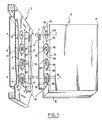
- the rows of connections 6 protrude inside the tank by corresponding openings made in the wall 3.
- In the bottom of the tray are provided with means for urging the circuit 4 towards the wall 3 on which it bears by shoulders (not shown) of the rows of connections 6.
- Each row 6 is intended to receive a series of male contacts 7 arranged at the rear edge of 'an electronic card 8.
- Each electronic card 8 is mounted in a housing of substantially flattened parallelepiped shape 9 made of synthetic material.
- the boxes 9 are stored next to each other in the tray, each facing a row of connections 6.
- the boxes 9 can each receive a terminal block (not shown) by which the electronic card 8 is connected for example to the bodies whose operation is to be monitored if it is an input card or to the bodies whose operation is to be controlled if it is an output card.
- the card 8 can also be a connection card to a calculation unit mounted directly on the front face 11 of the housing 9 or even at a distance from the tank.
- the housing 9 and the tank bottom 1 carry a coding device 12 intended to prevent a housing 9 provided with a card 8 having well-defined functions from being mounted on a row of connections 6 which, due to the points at which it is connected to the printed circuit 4, is not intended to receive a card 8 of this nature.
- the coding device 12 is of the mechanical type comprising male and female members which interlock when they are coded in a corresponding manner and when the box 9 is brought towards the bottom of the container 1 so as to engage the contacts 7 in the row of connections 6.
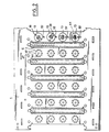
- the internal wall 3 of the bottom of the container 1 carries, next to the row of connections 6 that they protect, four coding members 13 made of synthetic material, only three of which are shown in FIG. 1 but the four are shown in Figure 2.
- the housing 9 On the side, the housing 9 has a rear face 14 facing in service towards the bottom 1 of the tank and which carries four female coding members 16 of which only three are shown in Figure 1.
- Each member male coding 13 is located on the wall 3 so as to be able to cooperate with a member 16 correspondingly located on the housing 9, and to fit together if they are coded correspondingly, when the housing 9 is brought towards the bottom 1 so as to make the connection.
- All of the male coding elements 13 are identical to each other, all of the female coding elements 16 are identical to each other, and each male coding element 13 has a shape allowing it to fit into any of the female coding members 16.
- Each coding member 13 or 16 is angularly movable, around an axis XX or YY respectively perpendicular to the wall 3 or 14 which carries it, between ten angular positions whose choice determines one of the four unit codes associated with the row of connections 6 or respectively to the housing 9.
- the male coding members carry eccentrically relative to the axis XX a finger 17 parallel to the latter and directed opposite the wall 3.
- the female coding members 16 have an orifice 18 having relative to the axis YY the same eccentricity as the finger 17 relative to the axis XX.
- a box 9 can be adapted to a given row of connections 6, we make sure that the angular positions of the four coding members 16, which determine the four unit codes of the box 9, and the four positions angular of the four coding members 13, which determine the four unit codes of the row of connections 6 correspond.
- the housing 9 is brought towards the bottom of the tank 1 with a view to introducing the rear edge of the card 8 into the row of connections 6, each of the fingers 17 is introduced into the orifice 18 of the coding member 16 coming opposite him. If at least one of the members 16 does not have an angular position corresponding to that of the member 13 opposite, the insertion of the card 8 in the row of connections 6 is impossible.
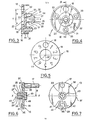
- the coding member 16 made of synthetic material, comprises a disc 19 whose plane is perpendicular to the 'YY axis and whose periphery is connected to a cylindrical neck 21 directed towards the wall 14 of the housing ( Figure 9).
- the disc 19 has in its center a cylindrical recess 22 directed opposite the wall 14.
- the disc 18 carries an axial stud 23 engaged in a bore 24 passing through the wall 14.
- the stud 23 consists of a cylindrical wall having four axial slots 26 extending over a certain length from its free end.
- the distance measured parallel to the axis between the end of the ramps 31 on the side of the disc 19 and the free end of the neck 21 is substantially equal to the thickness of the wall 14.
- the disc 19 At the cylindrical recess 22 of the disc 19 corresponds on the opposite face of the latter a cylindrical boss 32. Between the latter and the neck 21, the disc 19 still carries three studs 33 directed axially towards the wall 14.
- the axes of the studs 33 are all three at the same distance R from the axis YY and they extend axially beyond the neck 21 so as to be able to penetrate into a series of holes 34 made through the wall 14 and distributed angularly around the axis YY (see also in Figure 1 the location of the fourth member 16 not shown).
- the distance between the axis of the holes 34 and that of the hole 24 is also equal to R.
- the angular distance separating the studs 33 between them is equal to the angular distance separating two neighboring holes 34 or a multiple thereof.
- there are ten holes 34 separated from each other by angular intervals of 36 ° from axis to axis while on the member 16, one of the pins 33 is separated from each of the other two by a three times interval 36 ° 108 °.
- the axis of the orifice 18 which crosses the disc 19 is also at the distance R from the axis YY and is also at an angular distance from the pins 33 which is equal to the angular distance between two holes 34, or to a multiple of the latter.
- the orifice 18 is diametrically opposite the tenon 33 which is equidistant from the other two tenons 33.
- the disc 19 carries on its external face ten numerical marks 0 to 9 distributed angularly every 36 °, the zero being constituted by the orifice 18.
- one of the digital references is located opposite with a fixed indicator reference 36 carried by the wall 14 near each member 16 (FIG. 1).
- the member 13 comprises a flat disc 37 perpendicular to the axis XX itself consisting of a main body 38 and a tongue 39 connected to the body by an isthmus 41 defined between the bottom of two notches 42. These extend radially on either side of the tongue 39 from the periphery of the disc 37.
- the notches 42 have a certain circumferential dimension so that the tongue 39 has a certain elasticity in the circumferential direction relative to the body 38 of the disc 37 .
- the width and the thickness of the isthmus 41 are small enough so that the tongue 39 can flex elastically in the direction of the release of the tenon 46 away from the plane of the disc 37.
- the body 38 On its face directed towards the bottom 1 of the tank , the body 38 carries in the center of the disc 37 a stud 43 which is quite similar to the stud 23 of the members 16 except that it is shorter than the latter because the disc 37 bears directly against the bottom 1 of the tank and not by means of a neck such as 21.
- the tenon 43, directed along the axis XX is in service engaged in a bore 44 ( Figures 1, 2 and 9) and its snap-fit lugs 28 are engaged behind the shoulder formed by the internal face of the wall 3 without bending of the tongues 27.
- the tongue 39 carries on its face directed towards the bottom 1 of the tank a tenon 46 which in service is engaged in one of a choice of a series of ten holes 47 made through the wall 3 of the tank in locations distributed angularly around of axis XX.
- the finger 17 is fixed to the external face of the body 38 of the disc 37 in a position diametrically opposite to the stud 46.
- the axis of the finger 17 is at the distance R from the axis XX.
- the angular position of the holes 47 around the axis XX is such that when any of them is occupied by the pin 46, the finger 17 is located opposite one of the holes 34 made in the wall 14 of a housing 9 assumed to be brought towards the bottom 1 of the tank so that its card 8 is introduced into the row of connections 6 considered.
- the orifice 18 coincides with the bore 34 opposite which the finger 17 is located, and after connection, the finger 17 is engaged in the orifice 18 and in the hole 34 with which it coincides.
- the length of the finger 17 is such that when the coding of the members 13 and 16 is not consistent, the finger 17 abutting the disc 19 of the member 16 sufficiently prevents the advance of the housing 9 towards the bottom of the tank 1 for that the card cannot meet the contact elements of connection row 6 at all.
- the body 38 of the disc 37 also carries in the central position on its outer face a boss 48 which is housed in the recess 22 of the member 16 when the members 13 and 16 are mutually fitted.
- the boss 48 carries a slot 49 for the introduction of a screwdriver 51 ( Figure 10).
- the tenon 46 ( Figures 6 and 10) has a cylindrical base of very small axial dimension so that it does not occupy the entire thickness of the holes 47. The end of the tenon 46 is curved.
- each row of connections 6 are mounted four members 13 as shown for one of the rows in FIG. 2.
- a screwdriver 51 (FIG. 10) is then introduced into the slot 49 of each member 13 and one exercises to using the screwdriver 51 a rotational force on the member 13.
- this effort is sufficient to cause the stud 46 to come out of the bore 47 by bending the tongue 39 relative to the disc 37 in the direction of release of the post 46.
- the disc 37 can contribute to this release of the post 46 by taking off slightly from the wall 3 by penetration of the release ramps 31 into the bore 44 and light iron size of the corolla formed by the four tabs 27.
- the latter bears next to each member 13 an indicator mark 52. Any coding is thus characterized by a four-digit number and to carry out the coding it suffices to give each member 13 an angular position such that the digital marker located opposite the indicator marker 52 corresponds to one of the respective digits of the code.
- the boxes 9 are then correspondingly coded by snap-fastening the members 16 at the four locations provided. It is arranged to snap each member 16 directly into an angular position such that the number which is opposite the associated mark 36 is the same as the number selected with the corresponding member 13 associated with a row of connections 6 adapted to receive the housing 9 considered. It is in fact made so that when the same figure is selected for two members 13 and 16 positioned so as to be able to cooperate, the finger 17 of the member 13 is opposite the orifice 18 of the member 16. For to change the code of a box 9, it is necessary to extract the members 16 which are not set to the correct figure and re-engage them in the new angular position.
- the extraction can be done from the outside of the box 9 thanks to the release ramps 31 carried by the latching spouts 28 of the stud 23. It will however be noted that intentionally, it was made so that the modification of the code of the boxes 9 is relatively difficult because each box 9 contains a specific card 8 to which it is practical to associate an invariable code.
- the members 16 can, if necessary, undergo a slight angular displacement during the nesting in the orifices 18.
- the complete four-digit code of each row of connections 6 or of each box 9 comprises a partial two-digit code (the two from the top in FIG. 2) which is formed at the factory and which is intended not to allow to insert in the row of connections 6 only cards 8 intrinsically compatible with them.
- the four-digit code also includes a second partial code which is left available to further restrict the possibilities of connections depending on the particular use made of the programmable controller. In the factory, this second partial code is the same for all the rows of connections 6 and all the boxes 9. This second partial code is “00” at the factory outlet in the example shown. Regarding the boxes 9, rather than pre-coding the second partial code at the factory at "00", two coding members 16 can be supplied separately that the user can snap into the position corresponding to the second desired partial code.
- the coding device according to the invention considerably simplifies the coding operations, removes both the parts to be broken and the additional parts to be kept in stock and excludes any possibility of connection if the codes are different.
- the manufacture of the tank bottom and the mounting of the first coding members is particularly simple.
- the invention also offers the user the unprecedented but particularly interesting possibility of supplementing the coding as a function of the extrinsic data with a device of the automaton type.
- the coding members could consist of notched cursors, one carrying a finger which can engage in an orifice of the other when the codings are concordant.
Landscapes
- Details Of Connecting Devices For Male And Female Coupling (AREA)
- Toys (AREA)
- Coupling Device And Connection With Printed Circuit (AREA)
- Infusion, Injection, And Reservoir Apparatuses (AREA)
Claims (14)
Applications Claiming Priority (2)
| Application Number | Priority Date | Filing Date | Title |
|---|---|---|---|
| FR8306176 | 1983-04-15 | ||
| FR8306176A FR2544557B1 (fr) | 1983-04-15 | 1983-04-15 | Dispositif et procede de codage pour la connexion d'elements dans un automate programmable |
Publications (3)
| Publication Number | Publication Date |
|---|---|
| EP0125952A1 EP0125952A1 (de) | 1984-11-21 |
| EP0125952B1 true EP0125952B1 (de) | 1987-07-15 |
| EP0125952B2 EP0125952B2 (de) | 1992-09-16 |
Family
ID=9287896
Family Applications (1)
| Application Number | Title | Priority Date | Filing Date |
|---|---|---|---|
| EP84400721A Expired - Lifetime EP0125952B2 (de) | 1983-04-15 | 1984-04-11 | Modulvorrichtung mit mittels einer kodierten Verbindung an eine Leitung angeschlossenen elektronischen Karten |
Country Status (7)
| Country | Link |
|---|---|
| US (1) | US4595250A (de) |
| EP (1) | EP0125952B2 (de) |
| JP (2) | JPS60500741A (de) |
| CA (1) | CA1204860A (de) |
| DE (1) | DE3464826D1 (de) |
| FR (1) | FR2544557B1 (de) |
| WO (1) | WO1984004210A1 (de) |
Families Citing this family (26)
| Publication number | Priority date | Publication date | Assignee | Title |
|---|---|---|---|---|
| USD305117S (en) | 1985-10-12 | 1989-12-19 | Hosiden Electronics Co., Ltd. | Cassette holder for use in a computer |
| DE3603750C3 (de) * | 1986-02-06 | 1996-10-17 | Siemens Ag | Automatisierungsgerät |
| FR2603746B1 (fr) * | 1986-09-04 | 1989-09-08 | Souriau & Cie | Connecteur enfichable a detrompage, notamment pour l'aeronautique |
| US5014416A (en) * | 1988-03-15 | 1991-05-14 | Amp Incorporated | Single line, automatic key programming and connector transfer system |
| US4843714A (en) * | 1988-03-15 | 1989-07-04 | Amp Incorporated | Multiple line, automatic key programming and connector transfer system |
| EP0333385A1 (de) * | 1988-03-15 | 1989-09-20 | The Whitaker Corporation | Automatisches Schlüsselprogrammier- und Verbindertransportsystem |
| FR2629651B1 (fr) * | 1988-03-30 | 1992-08-28 | Telemecanique Electrique | Dispositif de derivation pour systemes de distribution electrique |
| US5419708A (en) * | 1993-12-21 | 1995-05-30 | International Business Machines Corp. | Printed circuit card with minor surface I/O pads |
| DE19643882B4 (de) * | 1996-10-30 | 2006-01-26 | Siemens Ag | Baugruppenträger mit Codiervorrichtung |
| DE29620410U1 (de) | 1996-11-22 | 1998-01-02 | Siemens AG, 80333 München | Einrichtung zur Codierung von Steckplätzen |
| JP5114481B2 (ja) * | 2006-07-27 | 2013-01-09 | スィロン エンジニアリング アンド マニュファクチュアリング, エルエルシー | 自動ハンドリング機器に用いられるコードピンを有するワンタッチアダプター |
| US7893012B2 (en) * | 2007-05-04 | 2011-02-22 | Ecolab Inc. | Solidification matrix |
| DE102007025458A1 (de) * | 2007-05-30 | 2008-12-04 | Siemens Ag | Codierung, insbesondere für eine Einschubanordnung eines elektrischen Schaltfeldes |
| WO2010026285A1 (en) * | 2008-09-08 | 2010-03-11 | Enfucell Oy (Ltd) | Anode and a method of manufacturing an anode |
| DE102008054015B4 (de) * | 2008-10-30 | 2012-11-08 | Lumberg Connect Gmbh | Steckverbinder |
| EP2766959B1 (de) * | 2011-10-13 | 2017-09-13 | Delphi International Operations Luxembourg S.à r.l. | Steckverbindersystem mit kodierungsmodulen |
| FR2981801B1 (fr) | 2011-10-20 | 2014-01-03 | Souriau | Systeme de detrompage pour connecteur et procede de montage de ce systeme sur un connecteur |
| DE102014200732B4 (de) * | 2014-01-16 | 2018-02-22 | Te Connectivity Germany Gmbh | Mechanisch programmierbare Kodiervorrichtung, Programmiervorrichtung und elektrisches Steckerelement mit selbigem sowie Kodierverfahren für einen elektrischen Steckverbinder |
| ES2650040T3 (es) | 2014-08-27 | 2018-01-16 | Selectron Systems Ag | Disposición con partes modulares y medios de codificación ajustables |
| RU2566496C1 (ru) | 2014-11-25 | 2015-10-27 | Игорь Борисович Медведев | Способ лечения закрытых повреждений мягких тканей в остром периоде и устройство для его осуществления |
| DE202015003177U1 (de) | 2015-04-30 | 2015-05-13 | Rosenberger Hochfrequenztechnik Gmbh & Co. Kg | Steckverbindung und Satz von Steckverbindungen |
| DE102016118870A1 (de) * | 2016-10-05 | 2018-04-05 | Lumberg Connect Gmbh | Steckverbinder mit entfernbaren Kodierstiften |
| EP3331334B1 (de) * | 2016-11-30 | 2021-05-19 | TE Connectivity Germany GmbH | Modulanordnung mit rückstellungsmechanismus |
| CN107039866B (zh) * | 2017-03-31 | 2018-11-20 | 国网河南省电力公司信息通信公司 | 大型视频矩阵柜理线架 |
| DE102019005611A1 (de) * | 2018-08-27 | 2020-02-27 | Sew-Eurodrive Gmbh & Co Kg | Elektrogerät, aufweisend ein Anschlussteil und ein mit dem Anschlussteil verbundenes Deckelteil |
| US10790609B2 (en) * | 2018-10-22 | 2020-09-29 | Honeywell International Inc. | Field termination assembly supporting use of mistake-proof keys |
Family Cites Families (16)
| Publication number | Priority date | Publication date | Assignee | Title |
|---|---|---|---|---|
| DE6605363U (de) * | 1964-02-01 | 1970-05-21 | Siemens Ag | Sicherheitsleiste fuer steckeinrichtungen |
| FR1389354A (fr) * | 1964-04-16 | 1965-02-12 | Northrop Corp | Moyen de fixation et de repérage |
| FR1531972A (fr) * | 1966-07-29 | 1968-07-05 | Bendix Corp | Perfectionnements aux guides d'indexation sélective pour connecteurs électriques de cartes à circuits imprimés |
| BE788506A (fr) * | 1971-09-07 | 1973-03-07 | Siemens Ag | Dispositif pour coordonner des emplacements de montage determines pour des blocs ou elements de construction plats enfichables |
| JPS5434183Y2 (de) * | 1973-12-27 | 1979-10-19 | ||
| DE2534775B2 (de) * | 1975-08-04 | 1977-06-30 | Siemens AG, 1000 Berlin und 8000 München | Anordnung bei flachbaugruppen mit frontsteckern |
| DE2541049C3 (de) * | 1975-09-15 | 1978-06-08 | Siemens Ag, 1000 Berlin Und 8000 Muenchen | Anordnung bei Flachbaugruppen mit Frontsteckern |
| US4032213A (en) * | 1976-01-29 | 1977-06-28 | The Bendix Corporation | Polarizing means for electrical connectors |
| CH607542A5 (en) * | 1976-12-16 | 1978-12-29 | Siemens Ag Albis | Printed circuit board mechanical coding system |
| JPS5848247Y2 (ja) * | 1977-08-17 | 1983-11-04 | セントラルコンベヤ−株式会社 | ロ−ラ−コンベヤ− |
| US4159862A (en) * | 1977-12-12 | 1979-07-03 | Fabri-Tek Incorporated | Removable female polarizing guide for electrical connectors |
| GB1568189A (en) * | 1978-02-22 | 1980-05-29 | Cannon Electric Great Britain | Electrical connectors |
| SU792386A2 (ru) * | 1978-08-28 | 1980-12-30 | Предприятие П/Я М-5774 | Электрический соединитель |
| JPS5767386U (de) * | 1980-10-09 | 1982-04-22 | ||
| US4398779A (en) * | 1980-12-18 | 1983-08-16 | Bell Telephone Laboratories, Incorporated | Keying apparatus for interconnecting electrical components |
| JPS57135082U (de) * | 1981-02-18 | 1982-08-23 |
-
1983
- 1983-04-15 FR FR8306176A patent/FR2544557B1/fr not_active Expired
-
1984
- 1984-04-11 US US06/691,520 patent/US4595250A/en not_active Expired - Lifetime
- 1984-04-11 EP EP84400721A patent/EP0125952B2/de not_active Expired - Lifetime
- 1984-04-11 WO PCT/FR1984/000100 patent/WO1984004210A1/fr not_active Ceased
- 1984-04-11 DE DE8484400721T patent/DE3464826D1/de not_active Expired
- 1984-04-11 JP JP59501549A patent/JPS60500741A/ja active Pending
- 1984-04-13 CA CA000452141A patent/CA1204860A/fr not_active Expired
-
1990
- 1990-06-25 JP JP1990066104U patent/JPH0528702Y2/ja not_active Expired - Lifetime
Also Published As
| Publication number | Publication date |
|---|---|
| JPH0528702Y2 (de) | 1993-07-23 |
| WO1984004210A1 (fr) | 1984-10-25 |
| CA1204860A (fr) | 1986-05-20 |
| FR2544557A1 (fr) | 1984-10-19 |
| FR2544557B1 (fr) | 1986-05-02 |
| US4595250A (en) | 1986-06-17 |
| EP0125952B2 (de) | 1992-09-16 |
| JPH038879U (de) | 1991-01-28 |
| JPS60500741A (ja) | 1985-05-16 |
| DE3464826D1 (en) | 1987-08-20 |
| EP0125952A1 (de) | 1984-11-21 |
Similar Documents
| Publication | Publication Date | Title |
|---|---|---|
| EP0125952B2 (de) | Modulvorrichtung mit mittels einer kodierten Verbindung an eine Leitung angeschlossenen elektronischen Karten | |
| EP0123590A1 (de) | Verbinder | |
| FR2768862A1 (fr) | Prise de courant faible a capuchon arriere organisateur | |
| FR2986915A1 (fr) | Dispositif detrompeur pour connecteur electrique | |
| CH679710A5 (de) | ||
| EP3407431A1 (de) | Kompaktstecker | |
| EP0172373B1 (de) | Vorrichtung zur optischen Anzeige von Durchstecken eines elektrischen Steckverbinders in eine Steckscheibe eines Luftfahrzeugs | |
| EP0734099A1 (de) | Modulare elektrische Reihenklemmenanordnung | |
| EP2182539B1 (de) | Elektrischer Einheit, bestehend aus einem elektrischen Stecker und einem elektrischen Modulgerät | |
| FR2612565A1 (fr) | Unite de commande pour commandes electro-hydrauliques de soutenement | |
| CA1226344A (fr) | Dispositif entree/sortie pour appareil du genre automate programmable, gamme de tels dispositifs et procede pour realiser leur bornier | |
| EP0394098A1 (de) | Auswechselbare Festplattenverbindungsvorrichtung | |
| FR2696840A1 (fr) | Fiche encliquetable de connexion de fibre optique, notamment fiche monobloc surmoulée. | |
| FR2635909A1 (fr) | Appareils de commande et/ou de protection electrique, elements constitutifs de ces appareils et ensembles constitues de ces elements | |
| FR2920256A1 (fr) | Socle de prise verrouille | |
| EP1318569A1 (de) | Elektrischen Steckanschluss mit Verschlussbuchsenblenden und Baureihe mit einem solchen Steckanschluss | |
| FR2628449A1 (fr) | Dispositif de commande pour machine a coudre industrielle | |
| EP0576344A1 (de) | Spreizelement für Gehäuse | |
| FR3105625A1 (fr) | Mécanisme d’appareillage électrique, ensemble électrique et appareillage électrique associés | |
| FR2589288A1 (fr) | Dispositif de connexion decentralisee d'un organe a une unite de commande programmable | |
| EP0299811A1 (de) | Vorgefertigte Stromzuleitung zur Realisierung von elektrischen Verteilungsschaltungen, die steuerbare Verteilungszonen mit verstellbaren Konfigurationen umfassen | |
| WO2000039895A1 (fr) | Dispositif de connexion pour cable coaxial | |
| FR3033215A1 (fr) | Prise de courant pour habitacle de vehicule | |
| EP0543981B1 (de) | Schnittstelleneinrichtung für eine verarbeitungseinheit, insbesondere eine programmierbare steuerung | |
| EP0657905B1 (de) | Kassette zur Aufnahme elektrischer Komponenten in einem Gehäuse |
Legal Events
| Date | Code | Title | Description |
|---|---|---|---|
| PUAI | Public reference made under article 153(3) epc to a published international application that has entered the european phase |
Free format text: ORIGINAL CODE: 0009012 |
|
| 17P | Request for examination filed |
Effective date: 19840414 |
|
| AK | Designated contracting states |
Designated state(s): BE DE FR GB IT NL SE |
|
| 17Q | First examination report despatched |
Effective date: 19860418 |
|
| ITF | It: translation for a ep patent filed | ||
| GRAA | (expected) grant |
Free format text: ORIGINAL CODE: 0009210 |
|
| AK | Designated contracting states |
Kind code of ref document: B1 Designated state(s): BE DE FR GB IT NL SE |
|
| REF | Corresponds to: |
Ref document number: 3464826 Country of ref document: DE Date of ref document: 19870820 |
|
| PLBI | Opposition filed |
Free format text: ORIGINAL CODE: 0009260 |
|
| 26 | Opposition filed |
Opponent name: SIEMENS AKTIENGESELLSCHAFT, BERLIN UND MUENCHEN Effective date: 19880413 |
|
| NLR1 | Nl: opposition has been filed with the epo |
Opponent name: SIEMENS AG. |
|
| PUAH | Patent maintained in amended form |
Free format text: ORIGINAL CODE: 0009272 |
|
| STAA | Information on the status of an ep patent application or granted ep patent |
Free format text: STATUS: PATENT MAINTAINED AS AMENDED |
|
| 27A | Patent maintained in amended form |
Effective date: 19920916 |
|
| AK | Designated contracting states |
Kind code of ref document: B2 Designated state(s): BE DE FR GB IT NL SE |
|
| ITF | It: translation for a ep patent filed | ||
| NLR2 | Nl: decision of opposition | ||
| NLR3 | Nl: receipt of modified translations in the netherlands language after an opposition procedure | ||
| ITTA | It: last paid annual fee | ||
| EAL | Se: european patent in force in sweden |
Ref document number: 84400721.1 |
|
| PGFP | Annual fee paid to national office [announced via postgrant information from national office to epo] |
Ref country code: NL Payment date: 19970320 Year of fee payment: 14 |
|
| PGFP | Annual fee paid to national office [announced via postgrant information from national office to epo] |
Ref country code: GB Payment date: 19970404 Year of fee payment: 14 |
|
| PGFP | Annual fee paid to national office [announced via postgrant information from national office to epo] |
Ref country code: SE Payment date: 19970425 Year of fee payment: 14 |
|
| PGFP | Annual fee paid to national office [announced via postgrant information from national office to epo] |
Ref country code: BE Payment date: 19970515 Year of fee payment: 14 |
|
| PG25 | Lapsed in a contracting state [announced via postgrant information from national office to epo] |
Ref country code: GB Free format text: LAPSE BECAUSE OF NON-PAYMENT OF DUE FEES Effective date: 19980411 |
|
| PG25 | Lapsed in a contracting state [announced via postgrant information from national office to epo] |
Ref country code: SE Free format text: LAPSE BECAUSE OF NON-PAYMENT OF DUE FEES Effective date: 19980412 |
|
| PG25 | Lapsed in a contracting state [announced via postgrant information from national office to epo] |
Ref country code: BE Free format text: LAPSE BECAUSE OF NON-PAYMENT OF DUE FEES Effective date: 19980430 |
|
| BERE | Be: lapsed |
Owner name: LA TELEMECANIQUE ELECTRIQUE Effective date: 19980430 |
|
| PG25 | Lapsed in a contracting state [announced via postgrant information from national office to epo] |
Ref country code: NL Free format text: LAPSE BECAUSE OF NON-PAYMENT OF DUE FEES Effective date: 19981101 |
|
| GBPC | Gb: european patent ceased through non-payment of renewal fee |
Effective date: 19980411 |
|
| NLV4 | Nl: lapsed or anulled due to non-payment of the annual fee |
Effective date: 19981101 |
|
| EUG | Se: european patent has lapsed |
Ref document number: 84400721.1 |
|
| PGFP | Annual fee paid to national office [announced via postgrant information from national office to epo] |
Ref country code: FR Payment date: 20020306 Year of fee payment: 19 |
|
| PGFP | Annual fee paid to national office [announced via postgrant information from national office to epo] |
Ref country code: DE Payment date: 20030306 Year of fee payment: 20 |
|
| PG25 | Lapsed in a contracting state [announced via postgrant information from national office to epo] |
Ref country code: FR Free format text: LAPSE BECAUSE OF NON-PAYMENT OF DUE FEES Effective date: 20031231 |
|
| REG | Reference to a national code |
Ref country code: FR Ref legal event code: ST |
|
| APAH | Appeal reference modified |
Free format text: ORIGINAL CODE: EPIDOSCREFNO |
|
| PLAB | Opposition data, opponent's data or that of the opponent's representative modified |
Free format text: ORIGINAL CODE: 0009299OPPO |