EP0125819B1 - Pince flexible pour robot, destinée à la préhension d'objets de forme irrégulière - Google Patents
Pince flexible pour robot, destinée à la préhension d'objets de forme irrégulière Download PDFInfo
- Publication number
- EP0125819B1 EP0125819B1 EP84302727A EP84302727A EP0125819B1 EP 0125819 B1 EP0125819 B1 EP 0125819B1 EP 84302727 A EP84302727 A EP 84302727A EP 84302727 A EP84302727 A EP 84302727A EP 0125819 B1 EP0125819 B1 EP 0125819B1
- Authority
- EP
- European Patent Office
- Prior art keywords
- gripper
- fixed axis
- arms
- axis
- relative
- Prior art date
- Legal status (The legal status is an assumption and is not a legal conclusion. Google has not performed a legal analysis and makes no representation as to the accuracy of the status listed.)
- Expired
Links
Images


Classifications
-
- B—PERFORMING OPERATIONS; TRANSPORTING
- B25—HAND TOOLS; PORTABLE POWER-DRIVEN TOOLS; MANIPULATORS
- B25J—MANIPULATORS; CHAMBERS PROVIDED WITH MANIPULATION DEVICES
- B25J15/00—Gripping heads and other end effectors
- B25J15/08—Gripping heads and other end effectors having finger members
- B25J15/10—Gripping heads and other end effectors having finger members with three or more finger members
- B25J15/103—Gripping heads and other end effectors having finger members with three or more finger members for gripping the object in three contact points
Definitions
- This invention relates to a gripper device of the flexible type applicable to industrial manipulators and the like and is particularly directed to an end-effector or gripper device design which accommodates tapered, twisted shapes.
- the complexity of the task, the shape and size of the object to be manipulated and the environment in which the end-effector must function are only several of the factors considered in the design of an end-effector or gripper device.
- the present invention provides an end effector or gripper device for manipulating objects having an irregular shape. It has been known that irregularly shaped objects can be manipulated with a gripper device having an air bladder built into the fingers. The air bladder inflates upon the fingers gripping the object to insure uniform holding forces throughout the gripper, as disclosed in "Robots and Remote Handling for Radioactive Materials”; Sheldon, O. L., et al., 2nd International Symposium On Industrial Robots, Tokyo Institute of Technology, Tokyo, Japan.
- An object is to provide an end-effector, or robot hand, which automatically adapts itself to the orientation of the object to be manipulated that is which permit the end-effector to conform to irregular shapes and which preserves the orientation of the object as it is transported from one work station to another.
- a gripper device of the flexible type comprising a structural frame having at one end thereof mounting means for establishing an interface with an industrial manipulator and a first fixed axis proximate the other end thereof, first gripper means rotatable about said first fixed axis, second gripper means rotatable about said first fixed axis, and actuating means for effecting the rotational movement of said first and second gripper means about said first fixed axis relative to each other, characterized in that said actuating means is mounted on the structural frame by means of a second fixed axis, about which said actuating means is rotatable, said actuating means being operably associated with the first and second gripper means by means of a first floating axis, whereby said first and second gripper means are rotatable about the first fixed axis relative to said structural frame member so that said first and second gripper means can be oriented with an object independent of the overall gripper device orientation relative to the object, and that brake means are operably
- the actuating means is operably associated with the first and second gripper means to effect the rotational movement thereof about the fixed axis.
- the brake means are operably associated with the first gripper means to selectively restrict the rotational movement of the gripper about the fixed axis.
- the actuating means effects the rotation of both the first and second gripper means relative to the fixed axis and frame member.
- the actuating means now effects only the rotational movement of the second gripper means relative to the fixed axis.
- the second gripper means consists of two arms which are connected and driven by a linkage which permits an additional degree of freedom through the independent rotational movement of each arm about the fixed axis. Although these arms are capable of independent movement, both are driven by the actuating means.
- the end-effector or gripper device functions as a gripper for irregular shapes. More particularly, this end-effector is designed to be mounted on a standard industrial manipulator and to grasp heavy and irregular shapes such as preforms for turbine blade forgings and the like.
- forging preforms are heavy and extremely irregular in shape and can be from 10 inches to several feet in length. Preforms have a roughly rectangular cross-section which varies in dimension and orientation along its length.
- the present end-effector has demonstrated a capacity to firmly grasp these irregularly shaped forging preforms and to accurately transport them from one location to another.
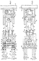
- an end-effector 11 for gripping irregular shapes is shown in side elevational and top and bottom plan views, respectively.
- the end effector 11 includes a structural frame member 13 which has at one end thereof a mounting plate means 15 for establishing a mechanical interface between the gripper and a conventional industrial manipulator schematically illustrated at 17.
- the frame member 13 provides a first axis 19 about which first gripper means 21 and second gripper means 23 can rotate both in unison with respect to the frame member 13 and independently of each other. Both the first and second gripper means, 21 and 23 respectively, are actuated by a single actuating means 25 which is pivotally mounted on the frame member 13.
- Brake means 27 are operably associated with the first gripper means 21 for restricting the pivotal movement thereof about the first axis 19. With the first gripper means 21 so restricted, the actuating means 25 now effects only the pivotal movement of the second gripper means 23 about the first axis 19.
- the fact that both the first and second gripper means are pivotable provides multiple degrees of freedom which permit the grippers to settle independently against the twisted and uneven shapes of the preforms.
- the brake means which restricts finger movement eliminates a degree of freedom that preserves the original orientation of the preform during relocation by the industrial manipulator.
- the first gripper means 21 includes a pair of arms 29 and 31 rotatably mounted by means of bushings 33 on a support shaft 35 which defines the first fixed axis 19.
- the portion of each arm 29 and 31 extending from the shaft 35 actually contacts the preform and may include gripping palms 37 thereon to protect the arms from excessive wear, corrosion or damage from a high temperature preform or the like.
- Such palms 37 are removably secured to the arm in a manner which facilitates ease of replacement.
- a further portion of each arm 29 and 31, as at 39, extends from the shaft 35 generally opposite the gripping portion thereof.
- a shaft 41, mounted in bushings 42 defines a first floating axis.
- a yoke like upper link 43 is rotatably mounted at one end on the shaft 41 by bushings 45 or the like while at the other end, the upper link 43 is rotatably mounted on shaft 47 by bushing 49 or the like.
- Shaft 47 defines a movable axis 51 which is operably associated with the actuating means 25 as will be hereinafter fully explained.
- the second gripper means 23 includes a pair of arms 53 and 55 rotatably mounted by means of bushings 57 on the support shaft 35 which defines the first fixed axis 19.
- the portion of each arm 53 and 55 which contacts the preform may include gripping palms 37.
- a further portion of each arm 53 and 55 extends from the shaft 35 in a generally, downward direction relative the corresponding portion of the arms 29 and 31 of the first gripper means 21.
- the first and second gripper means 21 and 23 function in a pliers-like fashion about the first axis 19.
- a shaft 59 extending between the arms 53 and 55 is mounted in each arm by means of a spherical bearing 61 and defines a second floating axis 63.
- a lower link 65 is centrally disposed by means of a spherical bearing 67 on the shaft 59 and is in communication with shaft 47 by means of bushing 69.
- the spherical bearing ball-joint linkage allows the arms 53 and 55 to settle independently against the twisted and uneven shapes of the preforms.
- the second floating axis 63 experiences gross movement in a generally vertical direction relative to the first fixed axis 19 and a twisting moment about the centrally disposed spherical bearing 67. It is the twisting moment which accommodates the independent movement of the arms 53 and 55.
- the actuating means 25 includes a hydraulic cylinder 71 mounted onto the frame member 13 by means of a bracket 75 and pin 77.
- the pin 77 defines a second fixed pivot point 79 on the frame member and permits rotational movement of the cylinder 71.
- the first and second fixed pivot points 19 and 79 respectively permit rotation of the components associated therewith in the same plane.
- the fluid conduits, valves, controls and the like are of conventional design and known to those skilled in the art. Accordingly, these components are not illustrated herein.
- the cylinder 71 includes a piston 73 which is threadedly attached to a connecting block 81.
- the first and second gripper means 21 and 23 are operably associated with the movable axis 51 of shaft 47.
- the shaft 47 is mounted by bushings 49 in a connecting link 83 from which a shaft 85 extends toward and is threadedly associated with, the connecting block 81.
- the brake means 27 is operably associated with the first finger means 21 to restrict the rotational movement of the arms 29 and 31 about the first fixed axis 19.
- an industrial disc brake 87 is mounted on the frame member 13 at a point where it is protected from the heat of the preforms.
- the disc brake 87 clamps a thin sheet of carbon steel 89 which is connected by the pair of elongated rods 91 to the arms 29 and 31 of the first gripper means 21.
- the rods 91 are connected at one end to a cross-member 93 which supports the sheet of carbon steel 89.
- the rods extend through, and are movably supported in a structural wall 95 of the frame member 13 by means of spherical bearings 97. At their other end, each rod is threadedly connected to a connecting block 99.
- a brake rod link 101 threadedly connected to each connecting block 99 completes the mechanical linkage between the disc brake 89 and the first finger means 21.
- the brake rod links 101 are rotatably attached to the arms 29 and 31 by means of pins 103 and bushings 105.
- the pins 103 and spherical bearings 97 permit the vertical displacement of the brakes mechanical linkage, i.e. rods 92, as the first finger means rotate about the first fixed axis 19.
- the connecting blocks 99 of the brake means as well as the connecting block 81 associated with the actuating means 25 permit the longitudinal adjustment of their associated linkages. While a dual brake linkage operably associated with both arms of the first gripper means is shown, a single linkage configuration can be utilized. The choice of a single or dual linkage system is made in view of the desired load handling capacity and stability characteristics of the end-effector.
- FIGS 4 through 7 show the present end-effector orienting itself with and engaging an irregularly shaped preform 111.
- the adaptability of this end-effector 11 and the degrees of freedom provided therein are described with reference to the first fixed axis 19 and the second fixed axis 79 of frame member 13 (not shown in these schematical representations).
- the first gripper means 21 and the second gripper means 23 are rotatably mounted at the first fixed axis 19 and the actuating means 25 is rotatable about the second fixed axis 79.
- the actuating means 25 is operably associated with the gripper means 21 and 23 at the movable or floating axis 51.
- the brake means 27 which is operably associated with the first gripper means 21.
- the gross orientation of the gripper means is possible because the actuating means is rotatably mounted on the second fixed axis 79. Additionally, the floating axis 51 is vertically displacable relative to the longitudinal axis of the end-effector. As the first gripper means 21 contacts the preform 111, it rotates about the first fixed axis 19 until a good seat is obtained as at 113 and 115. The gross downwardly rotational movement of both gripper means 21 and 23 is facilitated by the links 43 and 69 which connect the gripper means to the floating axis 51 which is vertically displaced and in turn causes the actuating means 25 to rotate in an upwardly direction. The brake means 27 is also subjected to some vertical displacement which is facilitated by the spherical bearings 97.
- the brake means 27 With the first gripper means 21 seated against the preform, the brake means 27 is engaged, locking the first gripper means 21 in a fixed position relative to the first fixed axis 19.
- the brake means 21 thus eliminates a degree of freedom of the end-effector's movement.
- the actuating means 25 draws the floating axis 51 generally backwardly and upwardly relative to the first fixed axis 19 causing the second gripper means 23 to close down against the preform 111.
- the second gripper means 23 may also have to accommodate a tapered, twisted shape of diminishing cross sectional dimension.
- the schematical front elevational view of the end-effector 11 on Figure 7 illustrates the adaptability of the two arms 53 and 55 to such a preform. Two degrees of articulation in the arms 53 and 55 of the second gripper means 23 allow arm 55 to contact the preform at 117 while permitting arm 53 to continue its closing motion until it contacts the preform at 119.
- the spherical bearings 61 and 67 provide this added degree of articulation needed to accommodate irregular shapes.
- the industrial manipulator with which the end-effector is associated can transport the preform from a first work station to a second work station.
- an end-effector which adapts itself automatically to the orientation of a preform or the like.
- the linkage in the end-effector allows the end-effector to adapt itself to the existing orientation of an object as well to grasp a wide variety of irregular twisted shapes. While the present invention has been described in combination with an industrial manipulator for use in a manufacturing process, the present invention is useful in any environment in which automation is applicable.
Landscapes
- Engineering & Computer Science (AREA)
- Robotics (AREA)
- Mechanical Engineering (AREA)
- Manipulator (AREA)
Claims (7)
Applications Claiming Priority (2)
| Application Number | Priority Date | Filing Date | Title |
|---|---|---|---|
| US491479 | 1983-05-04 | ||
| US06/491,479 US4545722A (en) | 1983-05-04 | 1983-05-04 | Flexible robot gripper for irregular shapes |
Publications (2)
| Publication Number | Publication Date |
|---|---|
| EP0125819A1 EP0125819A1 (fr) | 1984-11-21 |
| EP0125819B1 true EP0125819B1 (fr) | 1988-01-07 |
Family
ID=23952408
Family Applications (1)
| Application Number | Title | Priority Date | Filing Date |
|---|---|---|---|
| EP84302727A Expired EP0125819B1 (fr) | 1983-05-04 | 1984-04-24 | Pince flexible pour robot, destinée à la préhension d'objets de forme irrégulière |
Country Status (6)
| Country | Link |
|---|---|
| US (1) | US4545722A (fr) |
| EP (1) | EP0125819B1 (fr) |
| JP (2) | JPS59205287A (fr) |
| CA (1) | CA1227512A (fr) |
| DE (1) | DE3468362D1 (fr) |
| ES (1) | ES532126A0 (fr) |
Families Citing this family (21)
| Publication number | Priority date | Publication date | Assignee | Title |
|---|---|---|---|---|
| US4611846A (en) * | 1984-10-23 | 1986-09-16 | Amp Incorporated | Gripper head |
| US4696501A (en) * | 1986-01-30 | 1987-09-29 | Honeywell Inc. | Robot gripper |
| US4738583A (en) * | 1986-09-30 | 1988-04-19 | The United States Of America As Represented By The Administrator Of The National Aeronautics And Space Administration | Space spider crane |
| US4936241A (en) * | 1989-07-18 | 1990-06-26 | Hendrickson James P | Cooler assembly for catamarans |
| FR2652024B1 (fr) * | 1989-09-20 | 1992-04-24 | Aro Sa | Systeme de detalonnage pour pince a souder par resistance. |
| US5409280A (en) * | 1993-09-03 | 1995-04-25 | Weatherford/Lamb, Inc. | Pipe clamp |
| US6527686B1 (en) * | 2000-02-02 | 2003-03-04 | International Business Machines Corporation | Variable pitch spindle line drilling machine |
| JP4726241B2 (ja) * | 2007-02-16 | 2011-07-20 | シュンク・ジャパン株式会社 | 産業用ロボットのロボットハンド |
| JP5895337B2 (ja) | 2010-09-15 | 2016-03-30 | セイコーエプソン株式会社 | ロボット |
| JP5682810B2 (ja) * | 2010-09-15 | 2015-03-11 | セイコーエプソン株式会社 | ロボット |
| CN103846912A (zh) * | 2012-12-05 | 2014-06-11 | 黄广禧 | 垃圾裂解炉送杆机械手机构 |
| CN103851628B (zh) * | 2012-12-06 | 2016-06-29 | 广州市醇美环保科技有限公司 | 垃圾裂解炉压杆全自动接杆、卸杆装置 |
| ITMI20130108A1 (it) * | 2013-01-24 | 2014-07-25 | Stefano Gagliani | Dispositivo per la cernita automatica di biancheria per lavanderia industriale, e blocco pinza facente parte di detto dispositivo |
| US9757842B2 (en) * | 2015-05-05 | 2017-09-12 | Raytheon Company | Low particulating toggle clamp with secondary lock apparatus |
| US10011025B2 (en) | 2015-06-10 | 2018-07-03 | Phd, Inc. | Articulating gripper tooling |
| CN107720243A (zh) * | 2017-10-26 | 2018-02-23 | 广东玉兰集团股份有限公司 | 纸卷输送装置 |
| CN112297044A (zh) * | 2019-07-31 | 2021-02-02 | 中冶宝钢技术服务有限公司 | 渣钢铁抓取装置 |
| CN111409095A (zh) * | 2020-04-20 | 2020-07-14 | 西安工业大学 | 一种抓取异形硅钢片的机械爪 |
| US11345050B2 (en) * | 2020-10-20 | 2022-05-31 | Phd, Inc. | Articulating gripper tooling |
| US11459005B2 (en) | 2020-10-27 | 2022-10-04 | Raytheon Company | Ultra-clean manually-actuated clamping brake |
| CN116330337B (zh) * | 2023-05-25 | 2023-07-25 | 太原理工大学 | 一种露天采矿用抓取机械手 |
Family Cites Families (11)
| Publication number | Priority date | Publication date | Assignee | Title |
|---|---|---|---|---|
| GB1037682A (en) * | 1961-09-08 | 1966-08-03 | Molins Organisation Ltd | Mechanical handling apparatus for gripping articles |
| US3272347A (en) * | 1963-01-14 | 1966-09-13 | Jerome H Lemelson | Article manipulation apparatus |
| GB1156622A (en) * | 1966-09-19 | 1969-07-02 | Eaton Yale & Towne | Load-Handling Machine |
| US3630391A (en) * | 1969-01-28 | 1971-12-28 | Gulf & Western Ind Prod Co | Work gripper |
| DE1921959B2 (de) * | 1969-04-30 | 1974-04-18 | Fried. Krupp Gmbh, 4300 Essen | Traversen-Geschirr zum Transport von Brammen oder dergl |
| BE759705A (fr) * | 1969-12-02 | 1971-05-17 | British Steel Corp | Perfectionnements aux grappins de levage |
| US3620095A (en) * | 1970-09-03 | 1971-11-16 | Nasa | Mechanically actuated triggered hand |
| US3714870A (en) * | 1970-12-14 | 1973-02-06 | L Blatt | Dual grip actuating unit with travel cylinder assembly |
| US3963271A (en) * | 1974-10-15 | 1976-06-15 | Yamatake-Honeywell Company, Limited | Finger mechanisms of industrial robots |
| FR2457150A1 (fr) * | 1979-05-22 | 1980-12-19 | Citroen Sa | Pince eclipsable |
| SU841962A1 (ru) * | 1979-08-06 | 1981-06-30 | Институт Технической Кибернетики Анбелорусской Ccp | Захват промышленного робота |
-
1983
- 1983-05-04 US US06/491,479 patent/US4545722A/en not_active Expired - Fee Related
-
1984
- 1984-04-24 DE DE8484302727T patent/DE3468362D1/de not_active Expired
- 1984-04-24 EP EP84302727A patent/EP0125819B1/fr not_active Expired
- 1984-04-27 CA CA000452985A patent/CA1227512A/fr not_active Expired
- 1984-05-03 ES ES532126A patent/ES532126A0/es active Granted
- 1984-05-04 JP JP59088518A patent/JPS59205287A/ja active Pending
-
1987
- 1987-07-06 JP JP1987103788U patent/JPS6376493U/ja active Pending
Also Published As
| Publication number | Publication date |
|---|---|
| US4545722A (en) | 1985-10-08 |
| JPS6376493U (fr) | 1988-05-20 |
| DE3468362D1 (en) | 1988-02-11 |
| CA1227512A (fr) | 1987-09-29 |
| ES8505572A1 (es) | 1985-06-01 |
| ES532126A0 (es) | 1985-06-01 |
| JPS59205287A (ja) | 1984-11-20 |
| EP0125819A1 (fr) | 1984-11-21 |
Similar Documents
| Publication | Publication Date | Title |
|---|---|---|
| EP0125819B1 (fr) | Pince flexible pour robot, destinée à la préhension d'objets de forme irrégulière | |
| CN107921647B (zh) | 机器人夹持器 | |
| US5108140A (en) | Reconfigurable end effector | |
| US4806068A (en) | Rotary linear actuator for use in robotic manipulators | |
| KR101488540B1 (ko) | 물품 처리 장치, 시스템 및 방법 | |
| US9505126B2 (en) | Device for the movement and positioning of an element in space | |
| CN109910039B (zh) | 气动手指夹持与指根转位及电动指根转动的敏捷机械手 | |
| EP0022332A1 (fr) | Robots industriels | |
| EP0163065B1 (fr) | Manipulateur robotisé autopivotant | |
| WO2020009780A1 (fr) | Avant-bras robotiques | |
| CN210714524U (zh) | 一种钻杆接换工具 | |
| US7392722B2 (en) | Control unit with three parallel branches | |
| EP0114096A1 (fr) | Bras de robot | |
| US5738481A (en) | Universally actuable robot assembly | |
| KR101480346B1 (ko) | 평행링크 구조를 갖는 수직 다관절 로봇의 중력 보상 장치 | |
| CN113084790B (zh) | 位移和角位移转换放大的平移夹钳机械手及驱动控制方法 | |
| CN211916865U (zh) | 一种双臂搬运定位机器人 | |
| CN210456521U (zh) | 一种工件抓取装置 | |
| CN113733051A (zh) | 一种六自由度机械臂 | |
| EP3228425B1 (fr) | Dispositif pour le déplacement et le positionnement d'un élément dans l'espace | |
| CN113442156A (zh) | 一种基于新型两指机器人手的柔性夹持器 | |
| WO1995018702A1 (fr) | Pinces de serrage ajustables a des pieces de differentes tailles | |
| KR101805606B1 (ko) | 내열성, 내충격성, 내마모성이 강화된 그리퍼 | |
| CN205325673U (zh) | 紧凑型三轴工业机器人 | |
| CN110450186A (zh) | 一种用于机械制造的机械夹爪 |
Legal Events
| Date | Code | Title | Description |
|---|---|---|---|
| PUAI | Public reference made under article 153(3) epc to a published international application that has entered the european phase |
Free format text: ORIGINAL CODE: 0009012 |
|
| AK | Designated contracting states |
Designated state(s): CH DE FR GB IT LI |
|
| RIN1 | Information on inventor provided before grant (corrected) |
Inventor name: KUROKAWA, ELKI Inventor name: CUTKOSKY, MARK ROBERT |
|
| 17P | Request for examination filed |
Effective date: 19850521 |
|
| 17Q | First examination report despatched |
Effective date: 19860717 |
|
| ITF | It: translation for a ep patent filed |
Owner name: ING. ZINI MARANESI & C. S.R.L. |
|
| GRAA | (expected) grant |
Free format text: ORIGINAL CODE: 0009210 |
|
| AK | Designated contracting states |
Kind code of ref document: B1 Designated state(s): CH DE FR GB IT LI |
|
| REF | Corresponds to: |
Ref document number: 3468362 Country of ref document: DE Date of ref document: 19880211 |
|
| ET | Fr: translation filed | ||
| PLBE | No opposition filed within time limit |
Free format text: ORIGINAL CODE: 0009261 |
|
| STAA | Information on the status of an ep patent application or granted ep patent |
Free format text: STATUS: NO OPPOSITION FILED WITHIN TIME LIMIT |
|
| 26N | No opposition filed | ||
| PGFP | Annual fee paid to national office [announced via postgrant information from national office to epo] |
Ref country code: FR Payment date: 19900320 Year of fee payment: 7 |
|
| PGFP | Annual fee paid to national office [announced via postgrant information from national office to epo] |
Ref country code: GB Payment date: 19900331 Year of fee payment: 7 |
|
| ITTA | It: last paid annual fee | ||
| PGFP | Annual fee paid to national office [announced via postgrant information from national office to epo] |
Ref country code: CH Payment date: 19900627 Year of fee payment: 7 |
|
| PGFP | Annual fee paid to national office [announced via postgrant information from national office to epo] |
Ref country code: DE Payment date: 19900629 Year of fee payment: 7 |
|
| PG25 | Lapsed in a contracting state [announced via postgrant information from national office to epo] |
Ref country code: GB Effective date: 19910424 |
|
| PG25 | Lapsed in a contracting state [announced via postgrant information from national office to epo] |
Ref country code: LI Effective date: 19910430 Ref country code: CH Effective date: 19910430 |
|
| GBPC | Gb: european patent ceased through non-payment of renewal fee | ||
| PG25 | Lapsed in a contracting state [announced via postgrant information from national office to epo] |
Ref country code: FR Effective date: 19911230 |
|
| REG | Reference to a national code |
Ref country code: CH Ref legal event code: PL |
|
| PG25 | Lapsed in a contracting state [announced via postgrant information from national office to epo] |
Ref country code: DE Effective date: 19920201 |
|
| REG | Reference to a national code |
Ref country code: FR Ref legal event code: ST |