EP0125047B1 - Automotive vehicle tire and mounting system therefor - Google Patents
Automotive vehicle tire and mounting system therefor Download PDFInfo
- Publication number
- EP0125047B1 EP0125047B1 EP84302490A EP84302490A EP0125047B1 EP 0125047 B1 EP0125047 B1 EP 0125047B1 EP 84302490 A EP84302490 A EP 84302490A EP 84302490 A EP84302490 A EP 84302490A EP 0125047 B1 EP0125047 B1 EP 0125047B1
- Authority
- EP
- European Patent Office
- Prior art keywords
- tire
- bead
- drum
- ring member
- outboard
- Prior art date
- Legal status (The legal status is an assumption and is not a legal conclusion. Google has not performed a legal analysis and makes no representation as to the accuracy of the status listed.)
- Expired
Links
- 239000011324 bead Substances 0.000 claims abstract description 178
- 239000000565 sealant Substances 0.000 claims abstract description 24
- 230000000452 restraining effect Effects 0.000 claims abstract description 19
- 229910052751 metal Inorganic materials 0.000 claims abstract description 15
- 239000002184 metal Substances 0.000 claims abstract description 15
- 230000002787 reinforcement Effects 0.000 claims description 47
- 230000002093 peripheral effect Effects 0.000 claims description 10
- 238000007789 sealing Methods 0.000 claims description 3
- 238000003780 insertion Methods 0.000 claims description 2
- 230000037431 insertion Effects 0.000 claims description 2
- 230000003014 reinforcing effect Effects 0.000 claims description 2
- 238000006073 displacement reaction Methods 0.000 claims 1
- 238000009877 rendering Methods 0.000 claims 1
- 238000004519 manufacturing process Methods 0.000 description 8
- 238000010276 construction Methods 0.000 description 6
- 230000008901 benefit Effects 0.000 description 4
- 238000000034 method Methods 0.000 description 4
- 239000000853 adhesive Substances 0.000 description 3
- 230000001070 adhesive effect Effects 0.000 description 3
- 238000013461 design Methods 0.000 description 3
- 230000000694 effects Effects 0.000 description 3
- 239000000945 filler Substances 0.000 description 3
- 239000000463 material Substances 0.000 description 3
- 238000000926 separation method Methods 0.000 description 3
- 230000007547 defect Effects 0.000 description 2
- 239000004744 fabric Substances 0.000 description 2
- 230000008569 process Effects 0.000 description 2
- 230000009467 reduction Effects 0.000 description 2
- 238000005096 rolling process Methods 0.000 description 2
- 238000007493 shaping process Methods 0.000 description 2
- 239000007787 solid Substances 0.000 description 2
- 239000004677 Nylon Substances 0.000 description 1
- 241000287107 Passer Species 0.000 description 1
- 229920000297 Rayon Polymers 0.000 description 1
- 229910000831 Steel Inorganic materials 0.000 description 1
- 230000001133 acceleration Effects 0.000 description 1
- 230000002411 adverse Effects 0.000 description 1
- 238000004873 anchoring Methods 0.000 description 1
- 230000003466 anti-cipated effect Effects 0.000 description 1
- 229920006231 aramid fiber Polymers 0.000 description 1
- 238000005452 bending Methods 0.000 description 1
- 230000009286 beneficial effect Effects 0.000 description 1
- 230000015572 biosynthetic process Effects 0.000 description 1
- 239000007767 bonding agent Substances 0.000 description 1
- 230000008859 change Effects 0.000 description 1
- 150000001875 compounds Chemical class 0.000 description 1
- 230000006866 deterioration Effects 0.000 description 1
- 239000011152 fibreglass Substances 0.000 description 1
- -1 for example Substances 0.000 description 1
- 239000003365 glass fiber Substances 0.000 description 1
- 238000010348 incorporation Methods 0.000 description 1
- 239000000314 lubricant Substances 0.000 description 1
- 238000012423 maintenance Methods 0.000 description 1
- 230000007246 mechanism Effects 0.000 description 1
- 150000002739 metals Chemical class 0.000 description 1
- 229920001778 nylon Polymers 0.000 description 1
- 230000000704 physical effect Effects 0.000 description 1
- 229920000728 polyester Polymers 0.000 description 1
- 230000000644 propagated effect Effects 0.000 description 1
- 239000002964 rayon Substances 0.000 description 1
- 239000002990 reinforced plastic Substances 0.000 description 1
- 230000008439 repair process Effects 0.000 description 1
- 239000011435 rock Substances 0.000 description 1
- 239000003566 sealing material Substances 0.000 description 1
- 239000010959 steel Substances 0.000 description 1
- 239000000126 substance Substances 0.000 description 1
- 238000003466 welding Methods 0.000 description 1
Images


Classifications
-
- B—PERFORMING OPERATIONS; TRANSPORTING
- B60—VEHICLES IN GENERAL
- B60C—VEHICLE TYRES; TYRE INFLATION; TYRE CHANGING; CONNECTING VALVES TO INFLATABLE ELASTIC BODIES IN GENERAL; DEVICES OR ARRANGEMENTS RELATED TO TYRES
- B60C15/00—Tyre beads, e.g. ply turn-up or overlap
- B60C15/02—Seating or securing beads on rims
- B60C15/0209—Supplementary means for securing the bead
- B60C15/0223—Supplementary means for securing the bead the bead being secured by clip-hook elements not forming part of the rim flange
-
- B—PERFORMING OPERATIONS; TRANSPORTING
- B60—VEHICLES IN GENERAL
- B60B—VEHICLE WHEELS; CASTORS; AXLES FOR WHEELS OR CASTORS; INCREASING WHEEL ADHESION
- B60B21/00—Rims
- B60B21/10—Rims characterised by the form of tyre-seat or flange, e.g. corrugated
-
- B—PERFORMING OPERATIONS; TRANSPORTING
- B60—VEHICLES IN GENERAL
- B60B—VEHICLE WHEELS; CASTORS; AXLES FOR WHEELS OR CASTORS; INCREASING WHEEL ADHESION
- B60B23/00—Attaching rim to wheel body
- B60B23/04—Attaching rim to wheel body by bayonet joint, screw-thread, or like attachments
-
- B—PERFORMING OPERATIONS; TRANSPORTING
- B60—VEHICLES IN GENERAL
- B60B—VEHICLE WHEELS; CASTORS; AXLES FOR WHEELS OR CASTORS; INCREASING WHEEL ADHESION
- B60B25/00—Rims built-up of several main parts ; Locking means for the rim parts
- B60B25/22—Other apurtenances, e.g. for sealing the component parts enabling the use of tubeless tyres
-
- B—PERFORMING OPERATIONS; TRANSPORTING
- B60—VEHICLES IN GENERAL
- B60C—VEHICLE TYRES; TYRE INFLATION; TYRE CHANGING; CONNECTING VALVES TO INFLATABLE ELASTIC BODIES IN GENERAL; DEVICES OR ARRANGEMENTS RELATED TO TYRES
- B60C15/00—Tyre beads, e.g. ply turn-up or overlap
- B60C15/02—Seating or securing beads on rims
- B60C15/036—Tyres permanently fixed to the rim, e.g. by adhesive, by vulcanisation
-
- B—PERFORMING OPERATIONS; TRANSPORTING
- B60—VEHICLES IN GENERAL
- B60C—VEHICLE TYRES; TYRE INFLATION; TYRE CHANGING; CONNECTING VALVES TO INFLATABLE ELASTIC BODIES IN GENERAL; DEVICES OR ARRANGEMENTS RELATED TO TYRES
- B60C3/00—Tyres characterised by the transverse section
- B60C3/04—Tyres characterised by the transverse section characterised by the relative dimensions of the section, e.g. low profile
-
- Y—GENERAL TAGGING OF NEW TECHNOLOGICAL DEVELOPMENTS; GENERAL TAGGING OF CROSS-SECTIONAL TECHNOLOGIES SPANNING OVER SEVERAL SECTIONS OF THE IPC; TECHNICAL SUBJECTS COVERED BY FORMER USPC CROSS-REFERENCE ART COLLECTIONS [XRACs] AND DIGESTS
- Y02—TECHNOLOGIES OR APPLICATIONS FOR MITIGATION OR ADAPTATION AGAINST CLIMATE CHANGE
- Y02T—CLIMATE CHANGE MITIGATION TECHNOLOGIES RELATED TO TRANSPORTATION
- Y02T10/00—Road transport of goods or passengers
- Y02T10/80—Technologies aiming to reduce greenhouse gasses emissions common to all road transportation technologies
- Y02T10/86—Optimisation of rolling resistance, e.g. weight reduction
Definitions
- This invention relates to an automotive vehicle tire and a mounting system therefor, the design and construction of which cooperate to provide a optimized set of structural and operational characteristics.
- Automotive vehicles especially automobiles and trucks, which are adapted to be driven (or, in the case of trailers, to be towed) at relatively high speeds over streets and highways, ride on pneumatic tires mounted on metal wheels, each such wheel having an annular body portion and a transverse rim portion welded to the outer periphery of the body portion, the rim portion terminating at its opposite lateral boundaries in a pair of generally upstanding rim flanges and defining intermediate the flanges directly adjacent thereto a pair of bead seats on which the beads of the associated mounted tire are located.
- the rim portions of the wheels for passenger cars and light trucks are usually of the "drop center" variety, i.e.
- each wheel rim is a one- piece structure and is formed with a circumferential deep well intermediate the rim flanges.
- a deep well is provided to enable the circumferentially essentially inextensible but radially somewhat deformable beads of a tire to be slipped one after the other in well-known fashion over one of the rim flanges and onto the wheel rim.
- the tire is inflated to a pressure sufficiently high to cause the beads to be shifted laterally (i.e. axially) outwardly of the rim onto the bead seats and up against the rim flanges.
- a tire and wheel combination of this type is subject to a number of drawbacks and disadvantages, however, both in terms of problems that arise from the mounting of the tire on the wheel and in terms of problems that arise from the structural and operational characteristics of the tire per se, the wheel per se, and the assembled tire/wheel combination.
- wheel rim flanges being intended to laterally confine and retain the tire beads on the rim, extend essentially radially outwardly from the base of the rim, i.e. at an angle of usually at least about 45° to the base and frequently almost perpendicularly to the same, the outermost diameters of the rim flanges are of necessity considerably larger than the rim diameter, i.e. the diameter of the rim in the region of the bead seats.
- each bead is of necessity reinforced by a heavy bead wire arrangement, generally in the form of a strand of one or more relatively thick wires or ribbons wound for a multiplicity of turns into a bulky and circumferentially substantially inextensible albeit radially deformable bead wire core bundle.
- the cost of manufacturing such bead wire cores and preparing them for incorporation in the tire is, of course, a significant element of the overall cost of manufacturing the tire.
- the bulk of these bead wire cores makes it necessary that the radially inward regions of the sidewalls contiguous to the beads be made correspondingly thick through the addition of extra amuonts of rubber.
- the weight of the added rubber constitutes a substantial part of the weight of each tire and hence of the overall weight of the vehicle (and the vehicle weight is even higher whenever a fifth or spare tire is being carried in the vehicle), and obviously the power which must be expended in driving the vehicle corresponds directly to the weight of the vehicle.
- the “aspect ratio” of a tire is the ratio of the section height of the tire to the width of the section at its widest portion, with the section height being the perpendicular distance between two lines parallel to the tire axis, one located at the toe ring diameter and one tangent to the outer surface of the tread at the apex thereof, i.e. where it is intersected by the mid-circumferential plane of the tire.
- a low aspect ratio tire while generally characterized by good handling (cornering) and rolling resistance properties, also tends to give a rough ride and to be subject to certain sidewall problems.
- wheels with semi-drop center rims rims having only a shallow medial well formed therein
- flat base rims rims having no well at all formed therein
- a rim of such a wheel generally has one fixed and one demountable flange, with the demountable flange fitting into a gutter on the outboard edge of the rim to hold the tire in place.
- a divided wheel rim consists of two sections of either equal or unequal width, one of which carries a plurality of circumferentially distributed, axially extending studs or bolts while the other section is provided with a corresponding number of holes, so that the two sections can be bolted together with the aid of nuts in the same manner that a wheel is secured to a vehicle axle hub.
- the use of a divided rim of either of these types entails the use of a special bead- lock, of either the continuous channel type or the hinged segmental type, to hold a tire in position on the rim.
- a tubeless pneumatic tire having a generally toroidal shape defining a circumferential crown region, a tread overlying the crown region, and a pair of sidewalls extending generally radially inwardly from the tread and terminating in a pair of circumferential interiorly reinforced beads and two ring members constituting parts of a mounting system for the tire and each defining a respective bead seat, an associated bead restraining flange and an associated sidewall-supporting extension from the bead restraining.
- flange, the ring members being adhered to the tire at the inboard and outboard sides of the tire, respectively, the zone of adhesion in each case extending over the surface of the foot of the respective bead.
- the document further discloses a tire mounting system for use with a tubeless pneumatic tire, the mounting system including a drum having a drum-body adapted to be secured to the hub of a vehicle axle and a peripheral skirt secured to said drum-body and extending therefrom in the inboard direction of the vehicle when the drum is properly mounted on the hub of the vehicle axle, said system further including two ring members each defining a respective bead seat, an associated bead restraining flange and an associated.
- said ring members being adapted to be adhered to the tire at the inboard and outboard sides of the tire respectively, the zone of adhesion in each case extending over the surface of the foot of the respective bead, said outboard ring member being contoured to dispose the outboard bead seat, bead restraining flange and sidewall-supporting extension defined by said outboard ring member at locations relative to the axis of the tire corresponding to the locations of the inboard bead seat, bead restraining flange and sidewall-supporting extension defined by said inboard ring member.
- said zone of adhesion further extends over the axially outer side of the respective bead and thence over the surface of the portion of the associated sidewall located just radially outwardly of and contiguous to the bead, and each of said ring members is constructed and arranged for releasable attachment thereof to a vehicle axle-borne drum constituting another part of the mounting system for the tire.
- said skirt is provided at its inboard lateral boundary with a circumferential flange section and is devoid of any flange section at its outboard lateral boundary, said inboard ring member has contours corresponding substantially to those of said flange section of said skirt, and there is provided first attachment means for releasably securing the inboard ring member to said skirt along said flange section and second attachment means for releasably securing the outboard ring member to said drum body adjacent the outboard lateral boundary of said skirt.
- ring members which constitute parts of the mounting system for the tire and define the requisite bead seats and a pair of bead restraining flanges, the latter preferably being of lower than conventional height and having respective shallow, low-angle extensions matched to the aforesaid low-angle sidewall portions.
- the ring members over substantially the full extent of the bead seats, the bead restraining flanges and the low-angle extensions, are permanently adhered to the tire, e.g. by being bonded or vulcanized thereto, in the respective regions of the beads and the said radially inwardmost regions of the sidewalls contiguous to the beads.
- the ring members are further adapted to be mechanically releasably secured, as by means of bolts, lugs, or the like, to the vehicle axle-borne drum adjacent the opposite, i.e. the inboard and outboard, lateral boundaries of a peripheral skirt portion of the drum.
- the tire/drum combination is desirably made airtight through the application of a suitable sealant to the drum in the regions of the inner junctures between the skirt portion thereof and the two ring members.
- the sealant preferably is a material of any of the types disclosed in U.S. Patents Nos. 3981342, 4012567, and 4064922 and to the extent necessary the disclosures of those patents are hereby incorporated herein, but it will be apparent that possibly other types of sealing materials having acceptable physical properties may also be used.
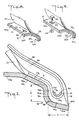
- a tire and mounting drum combination 20 including a pneumatic tire 21 and a drum 22 on which the tire is mounted in a manner to be more fully described hereinafter.
- the drum 22, which has a body portion 22a and a transverse peripheral skirt portion 22b, is secured at its mid-region to the hub 23 of a vehicle axle 24 by means of suitable bolts or screws 23a having specially configured heads, for example heads which are provided, as schematically indicated in Figs. 6 and 7, with internal hexagonal sockets (or any other type of special tool-engaging portions) designed to inhibit removal of the dtum from the axle without the use of special tools.
- the drum skirt 22b is provided at its free end with a circumferential flange section 25. No corresponding flange section is provided at the other side of the drum.
- the drum 22 is unidirectional, i.e. when property mounted on a vehicle axle it will always have its flanged side directed inboard of the vehicle (to the left in Fig. 1) and its flangeless side directed outboard of the vehicle (to the right in Fig. 1 and correspondingly, for reasons which will become clear presently, the tire 21 will always have to be mounted on the drum with a given one of its sides directed inboard and the other side directed outboard of the vehicle, so that, by design, mis- mounting of the tire is rendered effectively impossible. Portions of the drum 23 and the tire 21 are therefore, on occasion designated herein as being either "inboard” or "outboard” portions.
- the tire 21 has a generally toroidal shape and includes a tread 26 overlying the circumferential crown region of the tire, and a pair of sidewalls 27 and 28 extending generally radially inwardly from the tread and terminating in a pair of beads 29 and 30 reinforced interiorly by a pair of metal members 31 and 32.
- the body of the tire is reinforced by a carcass ply 33 of tire cords running from one bead to the other and anchored to the bead reinforcements 31 and 32, and a tread-reinforcing belt 34 of tire cords is interposed between the tread and the underlying portion of the carcass ply over the entire circumferential crown region of the tire.
- the anchoring of the carcass cords to the bead reinforcements is effected by turning the end regions 33a and 33b of the ply 33 up around the metal members 31 and 32 from the inside of the tire to the outside, and respective apex or filler strips 35 and 36 are fitted into the spaces above the metal members and between the main and turned-up portions of the carcass ply.
- Carcass ply turn-ups, bead wire reinforcements and apex strips are, of course, per se common elements of pneumatic tires, but as will be more fully explained presently the forms and arrangements of these elements in the tire 21 differ materially from those of their known antecedents in conventional tires.
- the tire cords of the carcass and the belt may be made of any of the materials that are conventionally used by tire manufacturers in such products, namely, rayon, nylon, polyester, steel, glass fiber, aramid fiber, and the like.
- the drum 22 and its component parts and adjuncts will generally be made of metal, but they could be molded of suitable reinforced plastics, e.g. molded fiberglass. It will be understood, however, that one or more of these known aspects of the various constructions described could be modified as desired.
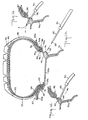
- the tire and drum combination according to the present invention further includes a pair of ring members 37 and 38 which are contoured to define respective bead seats 37a and 38a tapering radially inwardly of the tire at angles of approximately 5° to the tire axis (i.e. with a tolerance of about +1°) and respective contiguous bead restraining flanges 37b and 38b, the latter extending generally radially outwardly of the tire almost perpendicularly to the tire axis and having respective sidewall-supporting extensions 37c and 38c oriented at relatively shallow angles of about 25° to the tire axis.
- the ring members further have respective outer peripheral extensions 37d and 38d which (for a purpose that will become clear as the description proceeds) are oriented to extend almost parallel to the tire axis.
- the ring members 37 and 38 are permanently adhered to the tire 21 at the inboard and outboard sides of the tire.
- the zone of adhesion between the sections 37a, 37b and 37c of the inboard ring member 37 and the tire (this zone is designated Z and is diagrammatically represented by the cross-hatching in Fig. 3) extends over the surface of the foot 29a of the bead 29 from its heel 29b to its toe 29c, thence over the outer surface of the side portion 29d of the bead, and finally over the outer surface of the region 27a of the inboard sidewall 27 located just radially outwardly of and contiguous to the bead 29.
- the zone of adhesion between the sections 38a, 38b and 38c of the outboard ring member 38 and the tire correspondingly extends over the surface of the foot 30a of the bead 30 from its heel 30b to its - toe 30c, thence over the outer surface of the side portion 30d of the bead 30, and finally over the outer surface of the region 28a of the outboard sidewall 28 located just radially outwardly of and contiguous to the bead 30.
- the adhesive attachment of the ring members 37 and 38 to the tire can, of course, be effected during the manufacture of the tire by vulcanizing the ring members (if need be, suitably pretreated with a metal-to-rubber or a plastics-to-rubber adhesion-promoting substance of any of the types well known in the art) directly to the tire in the mold. Alternatively, however, it may be effected after the manufacture of the tire per se by adhering the ring members to the appropriate portions of the tire with the aid of suitable adhesive or bonding agents known in the industry for bonding rubber to metals, for example, adhesives such as are available commercially from Load Manufacturing Company under the registered trademark CHEM-LOK.
- the turned-up portions 33a and 33b of the carcass ply 33 are considerably shorter than is usually the case in conventional tires.
- the ply turn-ups terminate and are completely confined within the portions of the adhesion zones defined between the sections 37c and 38c of the ring members 37 and 38 and the respective tire sidewall regions 27a and 28a.
- the rubber apex or filler strips 35 and 36 used preferably have a relatively high Shore "A" hardness (on the order of about 90-94) and are considerably longer than is usually the case in conventional tires.
- the apex strips extend from the bead reinforcements 31 and 32 into the sidewalls 27 and 28 and terminate beyond the adhesion zones but short of the widest portion of the tire, i.e. short of the location of the greatest separation, denoted by the dimension g in Fig. 1, between the sidewalls 27 and 28.
- the apex strips terminate at a location between about 1/4 and 1/3 of the section height of the tire, the section height, denoted by the dimension h in Fig. 1, being the distance from a line parallel to the axis of the tire and constituting the toe ring diameter of the tire to a line parallel to the axis and tangent to the outer surface of the tread at its apex (i.e.
- the toe ring diameter is taken to be the line, parallel to the tire axis, which passes through the two points of intersection (only one of these, designated 39, is shown in Fig. 3 only) between the imaginary straight-line extensions of the tapered bottom surfaces of the bead portions 29a and 30a on the one hand and the associated generally radial outer side surfaces of the bead portions 29d and 30d on the other hand.
- the supported lower sidewall regions 27a and 28a are oriented at relatively shallow angles of about 25° to the tire axis (in what may be termed in effect a cantilever arrangement).
- This arrangement has certain beneficial effects on the ride and handling properties of the tire, i.e. it imparts an acceptible vertical elasticity to the tire and thereby tends to compensate for the hereinbefore mentioned somewhat less desirable prpoerties of the tire that result from its low aspect ratio.
- the adhesion of the lower sidewall regions and the beads to the respective sections of the the ring members in the manner shown ensures that circumferential bead slippage, radial bead rocking and bead roll-off, and bead chafing are effectively inhibited.
- the tire according to the present invention is also characterized by novel internal bead reinforcements.
- these novel bead reinforcements can have various cross-sectional configurations, as will be more fully described hereinafter, but in all cases each reinforcement will be in the form of a solid single-body or unitary metal member having no free ends, which can be achieved, for example, either by directly forming the member as a full ring or by first forming the member as a linear body, then bending the same into a circle of appropriate diameter to bring the ends of the body into contact with each other, and finally butt-welding the said ends to each other.
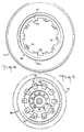
- the reinforcing members 31 and 32 preferably also have a generally U-shaped cross-section with a substantially uniform wall thickness.
- the inboard bead reinforcement 31 the same is characterized by an inner surface 31a of convexly semicircular curvature and an outer surface having a pair of flat, circumferentially extending, lateral regions 31b b and therebetween a circumferentially extending, medial, outwardly open channel 31c of concavely semicircular curvature.
- the outboard bead reinforcement 32 is identical in all respects with the reinforcement 31, as can be seen from Figs.
- inner and outer as applied to the surfaces of the reinforcement members 31 and 32, it should be understood, are here used to denote the respective surfaces of the annular or ring-shaped reinforcements which are directed inwardly and outwardly of the latter.
- each such bead reinforcement namely, the radius of curvature of its inner surface 31a or 32a, the radius of curvature of its channel 31c or 32c, the "height" of the U, i.e. the distance from the plane of the ends of the legs 31 b or 32b of the U to a plane tangent to the bottom of the U at its center line, and the wall thickness of the U, i.e. the difference between the said two radii
- the radius of curvature of its inner surface 31a or 32a the radius of curvature of its channel 31c or 32c
- the "height" of the U i.e. the distance from the plane of the ends of the legs 31 b or 32b of the U to a plane tangent to the bottom of the U at its center line
- the wall thickness of the U i.e. the difference between the said two radii
- each single-body single-turn reinforcement intended for use in a tire of a given rim size or bead diameter should be such as to provide such reinforcement with a metal surface area equal to approximately 50% of the metal surface area of a conventional multiple-wire multiple-turn bead core bundle intended for use in a correspondingly sized conventional tire. It will be apparent, therefore, that the bead reinforcements 31 and 32 are considerably smaller in volume and less bulky than conventional multiple-turn multiple-wire bead core bundles.
- the formation of the reinforcements with a substantially U-shaped cross-section through the provision of the longitudinal or circumferential channels in their outer surfaces entails two additional advantages.
- the presence of the upstanding lateral wall portions bounding the channel, i.e. the legs of the U ensures that the metal members have sufficient beam strength and stiffness (resistance to flexure) to withstand, with an adequate margin of safety, such stresses as they will be subjected to during handling as well as in use.
- the absence of material represented by the channels not only does not have an adverse effect on the strength and stiffness of the reinforcements but at the same time enables the weight of the reinforcements to be reduced as much as possible.
- a bead reinforcement according to the present invention would have a weight of about 56.7 g (2 ounces), which constitutes a weight saving of well over 60%
- conventional rubber-impregnated bead wire core bundle for a 13-inch bead diameter tire would weigh on the order of about 5.5 ounces
- a bead reinforcement according to the present invention would have a weight of about 2 ounces, which constitutes a weight saving of well over 60%.
- the tire has a low height ratio and the fact that the ring members 37 and 38, due to their adhesion to the beads and lower sidewall regions of the tire, aid the bead reinforcements in supporting the inflation forces encountered in the bead areas.
- the head reinforcements of the present invention are considerably smaller in bulk or volume than the conventional bead wire core bundles, not only the beads 29 and 30 themselves but also the corresponding bead seat sections 37a/38a and bead restraining flange sections 37b/38b of the ring members 37 and 38 may be made considerably smaller than they would have to be in a conventional tire/wheel combination.
- the widths of the bead feet 29a/30a and of the bead seat portions 37a/38a of the ring members, and the heights of the bead sides 29d/30d and of the bead restraining flange portions 37b/38b of the ring members, denoted by the respective dimensions s and f in Fig. 3, are 1.14 cm (0.450 inch) and 0.89 cm (0.350 inch), respectively. Both of these dimensions are substantially less than the dimensions of corresponding elements of conventional tires and wheel rims.
- bead reinforcements having the semicircular channeled cross-sectional configurations illustrated and so far described herein are preferred, the bead reinforcements may have slightly different cross-sectional configurations.
- the inner surfaces 31a/32a and the outer longitudinal channels 31c/32c of the reinforcements need not be precisely of semicircular curvature but could be otherwise arcuate (parabolic, hyperbolic, etc.).
- the legs of the U may also have free end sections that are linear, i.e. non-circular, and preferably parallel extensions of the circularly curved portions.
- the overall cross-sectional configuration could even be generally crescent-shaped, i.e. with the channel having a somewhat greater radius of curvature than the inner surface of the reinforcement member and with the wall thickness of the reinforcement cross-section as a consequence not being uniform throughout from one not necessarily flat lateral edge to the other. It would also be possible for the channel to be in the form of a narrow groove or even omitted altogether.
- the inner surface of the bead reinforcement may even have at least one generally flat circumferential portion, although iri such a case it would be preferred for the lateral boundaries of any such portion to be rounded. It will be understood, however, that such an arrangement too is to be considered an arcuate surface configuration.
- the herein disclosed semicircular configuration is preferred primarily because this is a good contour for the purposes of the tire building and shaping operations, in that it makes for a smooth fitting and rotation of the tire body plies around the reinforcements while at the same time providing an absence of relatively sudden directional changes for the portions of the plies passing about the reinforcements.
- the radially inwardmost sections of the apex or filler strips 35 and 36 will be contoured in accordance with the contours of the outer surface of the reinforcements.
- the apex strips in a corresponding fashion would be provided with peripheral projecting ribs matched to extend into the channels, thereby to provide a better interlock between the apex strips and the bead reinforcements during the tire building and shaping operations as well as in the finished tire.
- the attachment system must serve to ensure the proper location of the tire 21 on the drum and relative to the vehicle axle.
- the attachment system must also be such as to render and maintain the tire/drum combination fully airtight under all anticipated normal conditions of use, and it must be sufficiently sturdy to withstand the severe stresses to which it will be subjected while the tire is in service.
- the attachment system should be simple enough to permit the tire to be readily mounted on and demounted from the drum without entailing the imposition, during such operations, of any undue stresses on and deformations of the beads 29 and 30 and the bead reinforcements 31 and 32.
- the attachment system because of the uniqueness of the tire/drum combination and the complete departure of its construction from that of the heretofore conventional tire and wheel arrangements, should nevertheless also be so constructed as to inhibit its dismantling without the use of special tools.
- the attachment system for the inboard ring member 37 is relatively simple.
- the ring member 37 has an overall configuration matched to that of the flange section 25 of the skirt 22b of the drum 22 (see Figs. 1 and 2).
- the said flange section has a portion 25a corresponding to the bead seat section 37a of the ring member 37, a portion 25b corresponding to the bead restraining flange section 37b, a portion 25c corresponding to the lower sidewall supporting section 37c, and a peripheral extension 25d corresponding to the peripheral extension 37d.
- the taper angle of the bead seat defining section 37a of the ring member 37 is about 5° to the axis of the tire
- the taper angle of the portion 25a of the skirt flange section 25 is about 15° to the axis of the tire, as a result of which a small generally wedge-shaped space is formed between the ring member 37 and the skirt 22b at the region of juncture therebetween when the ring member is mounted on the drum.
- the attachment means which enable the ring member 37 to be securely fastened to the drum 22 include the peripheral extension 37d of the ring member and the extension 25d of the skirt flange section 25, the respective sets of circumferentially distributed openings or bores 40 and 41 formed therein, and the associated fasteners in the form of bolts 42 and nuts 43.
- the openings 40 in the ring member extension 37d as well as the heads of the bolts 42 are square in outline, while the bores 41 in the flange section extension 25d and the threaded shanks of the bolts are circular in outline, so that the bolts 42, the shanks of which are sufficient long to extend through the flange section extension 25d, can be prevented from rotating while the respective nuts 43 are tightened against the underside of the extension 25d.
- the attachment system for the outboard ring member 38 is somewhat more complex.
- the outboard ring member 38 in addition to the sections 38a to 38d already described, has a circumferential laterally inwardmost portion in the form of a plurality of projecting parts 44 adapted to closely overlie a circumferential radially outwardmost portion 45 of the drum body 22a.
- Each of the projecting parts 44 is provided with a respective opening 46, and correspondingly the drum body portion 45 is provided with a plurality of openings 47.
- the drum body is further provided with a plurality of struck-out parts 48 which are bent up to overlie the radially outwardmost portion 45 of the drum body.
- Each of the struck-out parts 48 is provided with an opening 49 aligned with the respective opening 47 in the drum body portion 45.
- the drum body 22a On its inboard side the drum body 22a is further provided with a plurality of bushings 50 which are welded or otherwise permanently secured to the drum body and have respective internally threaded bores 51 which are aligned with the openings 47 and 49.
- the openings 46, 47 and 49 are dimensioned to accommodate freely the threaded shank of a suitable bolt 52, which is adapted to extend through each set of such openings and be tightly screwed into the bores 51 of the bushings 50.
- the number of sets of associated struck-out parts, projecting parts, bushings and bolts can be varied as desired, depending on the strength of the connection required, but again it is contemplated that preferably at least ten and possibly as many as twelve or more such fastening means should be utilized.
- the outboard sidewall 28 of the tire is pushed inboardly until the projecting parts 44 of the outboard ring member are received in the spaces between the struck-out parts 48 and are pressed against the quantity of sealant 54, with the projecting parts circumferentially aligned with the gaps between the drum body portion 45 and the struck-out parts 48.
- the tire is then rotationally displaced, in the direction of the arrows shown in Fig.
- the tightening of the ring members 37 and 38 in place is, of course, effected with at least some of the respective quantities of sealant being confined between the ring members and the drum, while the remaining portions of the sealant lie outside these regions of confinement but still along the respective regions of juncture between the ring members and the drum, as shown in Fig. 1.
- the interior of the tire is thus rendered fully airtight, with no possibility of air losses occurring past the ring members.
- the tire/drum combination according to the present invention does possess a substantial run-flat capability and could be driven for considerable distances at reasonable speeds without risking ruination of either the tire or the drum.
- the valving system by which this problem is effectively overcome includes, in the illustrated form, a small depression or embossment 55 in the outboard ring member 38, the bottom of which depression is directed outwardly of the tire.
- a small hole 56 provided in the bottom of the depression 55 constitutes a passageway which is open both at the inside surface and at the outside surface of the ring member.
- the depression contains a quantity of sealant 57, preferably the same sealant as is used to seal the regions of juncture between the ring members and the drum, which is in direct contact with the ring member surface and completely covers the opening 56.
- the sealant will thereafter prevent any flow of air through the opening 56, while inflation of the tire can be effected very simply by extending an inflation needle 58, having an air outlet opening 59 at one end and connected to an air hose 60 at its other end, through the opening 56 and the quantity of sealant 57.
- an inflation needle 58 having an air outlet opening 59 at one end and connected to an air hose 60 at its other end, through the opening 56 and the quantity of sealant 57.
- one of the principal objectives is the provision of an optimized construction of the tire/drum combination. To this end it is contemplated to establish certain relations between the dimensions g, h and R of the tire and the dimension j of the mounting system (all of which dimensions are shown in Fig. 1) and hence to establish certain relations between as well as value ranges for the aspect ratio ⁇ , the height ratio 8 and the ring width ratio v.
- g is the distance, in a direction parallel to the tire axis, between the most widely separated portions of the sidewalls of the tire
- h is the radial dimension of the tire as measured from the toe ring diameter to a line parallel to the tire axis and tangent to the outer surface of the tread at its apex (i.e. where it is intersected by the median equatorial or mid-circumferential plane of the tire)
- j is the distance, in a direction parallel to the tire axis, between the outer extremities of the adhesion zones, i.e.
- the aspect ratio, the height ratio and the ring width ratio should conform substantially to the relations and and with the height ratio at its maximum being lower than the minimum height ratio of conventional P-metric tires (0.40 and above to more than 0.50), an aspect ratio as low as 0.60 or so and in any event lower than about 0.74 can be achieved.
- ⁇ the aspect ratio characterizing the tire need not lie precisely on the curve represented by a plot of against 8 in accordance with the first two of the above relations, but could deviate therefrom to a limited degree, say to the extent of about ⁇ 5%, and the term "conform substantially” as used herein with respect to the aspect ratio should, therefore, be interpreted as embracing a deviation of this magnitude.
Landscapes
- Engineering & Computer Science (AREA)
- Mechanical Engineering (AREA)
- Tires In General (AREA)
- Body Structure For Vehicles (AREA)
- Automobile Manufacture Line, Endless Track Vehicle, Trailer (AREA)
- Braking Systems And Boosters (AREA)
Priority Applications (1)
| Application Number | Priority Date | Filing Date | Title |
|---|---|---|---|
| AT84302490T ATE35114T1 (de) | 1983-04-12 | 1984-04-11 | Fahrzeugreifen und montageverfahren. |
Applications Claiming Priority (2)
| Application Number | Priority Date | Filing Date | Title |
|---|---|---|---|
| US48413083A | 1983-04-12 | 1983-04-12 | |
| US484130 | 1983-04-12 |
Publications (2)
| Publication Number | Publication Date |
|---|---|
| EP0125047A1 EP0125047A1 (en) | 1984-11-14 |
| EP0125047B1 true EP0125047B1 (en) | 1988-06-15 |
Family
ID=23922876
Family Applications (1)
| Application Number | Title | Priority Date | Filing Date |
|---|---|---|---|
| EP84302490A Expired EP0125047B1 (en) | 1983-04-12 | 1984-04-11 | Automotive vehicle tire and mounting system therefor |
Country Status (7)
| Country | Link |
|---|---|
| EP (1) | EP0125047B1 (enExample) |
| JP (2) | JPS59199309A (enExample) |
| AT (1) | ATE35114T1 (enExample) |
| BR (1) | BR8401461A (enExample) |
| CA (1) | CA1222440A (enExample) |
| DE (1) | DE3472080D1 (enExample) |
| TR (1) | TR22306A (enExample) |
Cited By (1)
| Publication number | Priority date | Publication date | Assignee | Title |
|---|---|---|---|---|
| WO2015156975A1 (en) * | 2014-04-07 | 2015-10-15 | Bridgestone Americas Tire Operations, Llc | Tire with pre-stressed toroidal element |
Families Citing this family (14)
| Publication number | Priority date | Publication date | Assignee | Title |
|---|---|---|---|---|
| JPS6118901U (ja) * | 1984-07-10 | 1986-02-03 | 本田技研工業株式会社 | 二つ割リムの組付構造 |
| US5507333A (en) * | 1994-02-22 | 1996-04-16 | Trinc, Tire & Rim, Incorporated | Composite wheel |
| US5638591A (en) * | 1995-05-24 | 1997-06-17 | Lamping; Bruce Alan | Method for restoring a wheel beadseat |
| FR2743530B1 (fr) * | 1996-01-15 | 1998-02-13 | Michelin & Cie | Ensemble pneumatique-jante pour vehicule poids-lourds |
| FR2874536B1 (fr) * | 2004-09-01 | 2008-02-15 | Tramont Sa | Jante et procede de fabrication d'une jante pourvue de moyens d'anti-dejantage |
| WO2009103252A2 (en) * | 2008-02-21 | 2009-08-27 | Coda Development, S.R.O. | A device for adjustment of pressure in tires. |
| CZ2009748A3 (cs) | 2009-11-11 | 2011-10-05 | Sithold S.R.O. | Zarízení pro transport vzduchu v pneumatice |
| CZ2011757A3 (cs) | 2011-11-22 | 2013-05-29 | Sithold S.R.O | Zarízení pro udrzování a zmenu tlaku v pneumatice |
| WO2019002792A1 (fr) * | 2017-06-30 | 2019-01-03 | Compagnie Generale Des Etablissements Michelin | Ensemble roulant comportant une jante dont le rebord forme un support de largeur axiale etendue |
| CN110914066B (zh) * | 2017-06-30 | 2023-05-05 | 米其林集团总公司 | 具有优化的轮辋凸缘形状的车轮轮辋 |
| CN110891798B (zh) * | 2017-06-30 | 2023-08-01 | 米其林集团总公司 | 具有高度降低的轮辋凸缘的轮辋 |
| FR3082147B1 (fr) * | 2018-06-08 | 2021-05-28 | Michelin & Cie | Ensemble jante et extenseur flexible pour ensemble roulant |
| KR102843079B1 (ko) * | 2020-03-04 | 2025-08-07 | 현대자동차주식회사 | 타이어의 공력을 개선하기 위한 인서트 러버 및 그 설치방법 |
| CN112477523B (zh) * | 2020-12-11 | 2022-09-13 | 芜湖集拓实心胎有限公司 | 一种支架搬运车用实心轮胎 |
Citations (1)
| Publication number | Priority date | Publication date | Assignee | Title |
|---|---|---|---|---|
| US3938573A (en) * | 1974-04-11 | 1976-02-17 | The B. F. Goodrich Company | Run flat tire and wheel assembly |
Family Cites Families (13)
| Publication number | Priority date | Publication date | Assignee | Title |
|---|---|---|---|---|
| US3425475A (en) * | 1966-10-26 | 1969-02-04 | Goodrich Co B F | Integral tire and hub |
| US3515196A (en) * | 1967-11-21 | 1970-06-02 | Goodrich Co B F | Tire and wheel for passenger automobiles |
| GB1459998A (en) * | 1972-12-19 | 1976-12-31 | Bugden H | Vehicle wheels |
| US4029139A (en) * | 1976-01-05 | 1977-06-14 | The Goodyear Tire & Rubber Company | Tire and rim assembly |
| US4096900A (en) * | 1976-01-05 | 1978-06-27 | The Goodyear Tire & Rubber Company | Earthmover tire and rim assembly |
| FR2367626A1 (fr) * | 1976-10-13 | 1978-05-12 | Kleber Colombes | Pneumatique pour roue motrice de tracteur agricole ou applications similaires |
| DE2829452A1 (de) * | 1978-07-05 | 1980-01-17 | Euteco Spa | Reifen |
| US4325422A (en) * | 1978-12-29 | 1982-04-20 | Dunlop Limited | Pneumatic tire and wheel rim assemblies |
| JPS5623805A (en) * | 1979-08-07 | 1981-03-06 | Iseki Agricult Mach | Automatic direction control device in combined harvester |
| DE2940221C2 (de) * | 1979-10-04 | 1983-10-13 | Hahn GmbH & Co, 5992 Nachrodt | Wulstkern für schlauchlose Fahrzeugluftreifen |
| FR2506683A1 (fr) * | 1980-06-04 | 1982-12-03 | Michelin Rech Tech | Pneumatique a carcasse radiale pour roues de vehicules moyens et gros porteurs |
| IT1144201B (it) * | 1981-04-29 | 1986-10-29 | Firestone International | Pneumatico per veicolo stradale |
| DE3206171A1 (de) * | 1982-02-20 | 1983-08-25 | Continental Gummi-Werke Ag, 3000 Hannover | Fahrzeugrad |
-
1984
- 1984-03-29 BR BR8401461A patent/BR8401461A/pt unknown
- 1984-04-04 CA CA000451260A patent/CA1222440A/en not_active Expired
- 1984-04-11 EP EP84302490A patent/EP0125047B1/en not_active Expired
- 1984-04-11 AT AT84302490T patent/ATE35114T1/de not_active IP Right Cessation
- 1984-04-11 DE DE8484302490T patent/DE3472080D1/de not_active Expired
- 1984-04-11 JP JP59072611A patent/JPS59199309A/ja active Granted
-
1986
- 1986-04-12 TR TR2863A patent/TR22306A/xx unknown
-
1991
- 1991-08-12 JP JP3201734A patent/JPH05609A/ja active Pending
Patent Citations (1)
| Publication number | Priority date | Publication date | Assignee | Title |
|---|---|---|---|---|
| US3938573A (en) * | 1974-04-11 | 1976-02-17 | The B. F. Goodrich Company | Run flat tire and wheel assembly |
Cited By (3)
| Publication number | Priority date | Publication date | Assignee | Title |
|---|---|---|---|---|
| WO2015156975A1 (en) * | 2014-04-07 | 2015-10-15 | Bridgestone Americas Tire Operations, Llc | Tire with pre-stressed toroidal element |
| CN106163832A (zh) * | 2014-04-07 | 2016-11-23 | 普利司通美国轮胎运营有限责任公司 | 具有预加应力环形元件的轮胎 |
| US10052919B2 (en) | 2014-04-07 | 2018-08-21 | Bridgestone Americas Tire Operations, Llc | Tire with pre-stressed toroidal element |
Also Published As
| Publication number | Publication date |
|---|---|
| JPS59199309A (ja) | 1984-11-12 |
| EP0125047A1 (en) | 1984-11-14 |
| JPH0476801B2 (enExample) | 1992-12-04 |
| BR8401461A (pt) | 1984-11-13 |
| JPH05609A (ja) | 1993-01-08 |
| ATE35114T1 (de) | 1988-07-15 |
| DE3472080D1 (en) | 1988-07-21 |
| CA1222440A (en) | 1987-06-02 |
| TR22306A (tr) | 1987-01-15 |
Similar Documents
| Publication | Publication Date | Title |
|---|---|---|
| US4658876A (en) | Automotive vehicle tire and mounting system therefor | |
| EP0125047B1 (en) | Automotive vehicle tire and mounting system therefor | |
| JP4221622B2 (ja) | ビード/リム境界部を改良したランフラットタイヤ | |
| JP3854311B2 (ja) | 低アスペクト比トラックタイヤ | |
| US3935892A (en) | Pneumatic tired wheel | |
| US5634993A (en) | Rim and assembly of tire and ring-shaped tread support on same | |
| US5238040A (en) | Self-supporting carcass for motor-vehicle tires | |
| US5749982A (en) | Rim and assembly of tire and/or ring-shaped tread support on same | |
| AU736829B2 (en) | Pneumatic tire including belt and circumferential ribs | |
| US4726408A (en) | Pneumatic tire bead portion structure | |
| KR950013751A (ko) | 개선된 비포장도로용 공기 타이어 | |
| US5513686A (en) | Tire bead structure for heavy vehicles | |
| CA1126635A (en) | Pneumatic safety tire | |
| AU740290B2 (en) | Wire-less bead for a tyre | |
| US6491077B1 (en) | Tire with specified crown reinforcement and carcass profile | |
| JP3487910B2 (ja) | タイヤのトレッド支持装置 | |
| US6631747B2 (en) | Assembly for mounting a tire on a hub | |
| JPH07164835A (ja) | ラジアルプライ空気入りタイヤ | |
| EP0958153B1 (en) | Heavy duty tire with specified bead design | |
| JP2002326503A (ja) | リムおよび支持用支持体からなる組立体 | |
| US7281553B1 (en) | Tire with compression-bearing hoop structure | |
| EP0133150B1 (en) | Closed torus tire | |
| US4667721A (en) | Pneumatic tire | |
| CA1249210A (en) | Automotive vehicle tire and mounting system therefor | |
| JP2703664B2 (ja) | ラジアルカーカス補強材を備えたタイヤ |
Legal Events
| Date | Code | Title | Description |
|---|---|---|---|
| PUAI | Public reference made under article 153(3) epc to a published international application that has entered the european phase |
Free format text: ORIGINAL CODE: 0009012 |
|
| AK | Designated contracting states |
Designated state(s): AT BE CH DE FR GB IT LI LU NL SE |
|
| 17P | Request for examination filed |
Effective date: 19850507 |
|
| 17Q | First examination report despatched |
Effective date: 19861001 |
|
| ITF | It: translation for a ep patent filed | ||
| GRAA | (expected) grant |
Free format text: ORIGINAL CODE: 0009210 |
|
| RAP1 | Party data changed (applicant data changed or rights of an application transferred) |
Owner name: THE UNIROYAL GOODRICH TIRE COMPANY |
|
| AK | Designated contracting states |
Kind code of ref document: B1 Designated state(s): AT BE CH DE FR GB IT LI LU NL SE |
|
| PG25 | Lapsed in a contracting state [announced via postgrant information from national office to epo] |
Ref country code: NL Effective date: 19880615 Ref country code: LI Effective date: 19880615 Ref country code: CH Effective date: 19880615 Ref country code: BE Effective date: 19880615 Ref country code: AT Effective date: 19880615 |
|
| REF | Corresponds to: |
Ref document number: 35114 Country of ref document: AT Date of ref document: 19880715 Kind code of ref document: T |
|
| PG25 | Lapsed in a contracting state [announced via postgrant information from national office to epo] |
Ref country code: SE Effective date: 19880630 |
|
| REF | Corresponds to: |
Ref document number: 3472080 Country of ref document: DE Date of ref document: 19880721 |
|
| ET | Fr: translation filed | ||
| REG | Reference to a national code |
Ref country code: CH Ref legal event code: PL |
|
| NLV1 | Nl: lapsed or annulled due to failure to fulfill the requirements of art. 29p and 29m of the patents act | ||
| PGFP | Annual fee paid to national office [announced via postgrant information from national office to epo] |
Ref country code: LU Payment date: 19890301 Year of fee payment: 6 |
|
| PGFP | Annual fee paid to national office [announced via postgrant information from national office to epo] |
Ref country code: SE Payment date: 19890410 Year of fee payment: 6 |
|
| PLBE | No opposition filed within time limit |
Free format text: ORIGINAL CODE: 0009261 |
|
| STAA | Information on the status of an ep patent application or granted ep patent |
Free format text: STATUS: NO OPPOSITION FILED WITHIN TIME LIMIT |
|
| PG25 | Lapsed in a contracting state [announced via postgrant information from national office to epo] |
Ref country code: LU Free format text: LAPSE BECAUSE OF NON-PAYMENT OF DUE FEES Effective date: 19890430 |
|
| 26N | No opposition filed | ||
| PGFP | Annual fee paid to national office [announced via postgrant information from national office to epo] |
Ref country code: GB Payment date: 19910403 Year of fee payment: 8 |
|
| PGFP | Annual fee paid to national office [announced via postgrant information from national office to epo] |
Ref country code: FR Payment date: 19910426 Year of fee payment: 8 |
|
| ITTA | It: last paid annual fee | ||
| PGFP | Annual fee paid to national office [announced via postgrant information from national office to epo] |
Ref country code: DE Payment date: 19910430 Year of fee payment: 8 |
|
| PG25 | Lapsed in a contracting state [announced via postgrant information from national office to epo] |
Ref country code: GB Effective date: 19920411 |
|
| GBPC | Gb: european patent ceased through non-payment of renewal fee | ||
| PG25 | Lapsed in a contracting state [announced via postgrant information from national office to epo] |
Ref country code: FR Effective date: 19921230 |
|
| PG25 | Lapsed in a contracting state [announced via postgrant information from national office to epo] |
Ref country code: DE Effective date: 19930101 |
|
| REG | Reference to a national code |
Ref country code: FR Ref legal event code: ST |