EP0124902A1 - Verfahren und Vorrichtung zur Herstellung von Streben - Google Patents
Verfahren und Vorrichtung zur Herstellung von Streben Download PDFInfo
- Publication number
- EP0124902A1 EP0124902A1 EP84105157A EP84105157A EP0124902A1 EP 0124902 A1 EP0124902 A1 EP 0124902A1 EP 84105157 A EP84105157 A EP 84105157A EP 84105157 A EP84105157 A EP 84105157A EP 0124902 A1 EP0124902 A1 EP 0124902A1
- Authority
- EP
- European Patent Office
- Prior art keywords
- access
- tubular element
- forming
- aperture
- forming tool
- Prior art date
- Legal status (The legal status is an assumption and is not a legal conclusion. Google has not performed a legal analysis and makes no representation as to the accuracy of the status listed.)
- Withdrawn
Links
- 238000000034 method Methods 0.000 title claims description 15
- 238000004519 manufacturing process Methods 0.000 title claims description 10
- 230000015572 biosynthetic process Effects 0.000 claims abstract description 19
- 238000005755 formation reaction Methods 0.000 claims abstract description 19
- 239000000463 material Substances 0.000 claims abstract description 17
- 229910001220 stainless steel Inorganic materials 0.000 abstract description 7
- 239000010935 stainless steel Substances 0.000 abstract description 7
- 238000006073 displacement reaction Methods 0.000 abstract description 5
- 238000010438 heat treatment Methods 0.000 abstract description 3
- 238000003466 welding Methods 0.000 abstract description 2
- 238000004080 punching Methods 0.000 description 13
- 238000001125 extrusion Methods 0.000 description 7
- POIUWJQBRNEFGX-XAMSXPGMSA-N cathelicidin Chemical compound C([C@@H](C(=O)N[C@@H](CCCNC(N)=N)C(=O)N[C@@H](CCCCN)C(=O)N[C@@H](CO)C(=O)N[C@@H](CCCCN)C(=O)N[C@@H](CCC(O)=O)C(=O)N[C@@H](CCCCN)C(=O)N[C@@H]([C@@H](C)CC)C(=O)NCC(=O)N[C@@H](CCCCN)C(=O)N[C@@H](CCC(O)=O)C(=O)N[C@@H](CC=1C=CC=CC=1)C(=O)N[C@@H](CCCCN)C(=O)N[C@@H](CCCNC(N)=N)C(=O)N[C@@H]([C@@H](C)CC)C(=O)N[C@@H](C(C)C)C(=O)N[C@@H](CCC(N)=O)C(=O)N[C@@H](CCCNC(N)=N)C(=O)N[C@@H]([C@@H](C)CC)C(=O)N[C@@H](CCCCN)C(=O)N[C@@H](CC(O)=O)C(=O)N[C@@H](CC=1C=CC=CC=1)C(=O)N[C@@H](CC(C)C)C(=O)N[C@@H](CCCNC(N)=N)C(=O)N[C@@H](CC(N)=O)C(=O)N[C@@H](CC(C)C)C(=O)N[C@@H](C(C)C)C(=O)N1[C@@H](CCC1)C(=O)N[C@@H](CCCNC(N)=N)C(=O)N[C@@H]([C@@H](C)O)C(=O)N[C@@H](CCC(O)=O)C(=O)N[C@@H](CO)C(O)=O)NC(=O)[C@H](CC=1C=CC=CC=1)NC(=O)[C@H](CC(O)=O)NC(=O)CNC(=O)[C@H](CC(C)C)NC(=O)[C@@H](N)CC(C)C)C1=CC=CC=C1 POIUWJQBRNEFGX-XAMSXPGMSA-N 0.000 description 5
- 239000007788 liquid Substances 0.000 description 2
- 238000003825 pressing Methods 0.000 description 2
- 230000005923 long-lasting effect Effects 0.000 description 1
- 238000012423 maintenance Methods 0.000 description 1
- 239000002184 metal Substances 0.000 description 1
- 238000005498 polishing Methods 0.000 description 1
Images


Classifications
-
- E—FIXED CONSTRUCTIONS
- E04—BUILDING
- E04F—FINISHING WORK ON BUILDINGS, e.g. STAIRS, FLOORS
- E04F11/00—Stairways, ramps, or like structures; Balustrades; Handrails
- E04F11/18—Balustrades; Handrails
- E04F11/181—Balustrades
-
- B—PERFORMING OPERATIONS; TRANSPORTING
- B21—MECHANICAL METAL-WORKING WITHOUT ESSENTIALLY REMOVING MATERIAL; PUNCHING METAL
- B21D—WORKING OR PROCESSING OF SHEET METAL OR METAL TUBES, RODS OR PROFILES WITHOUT ESSENTIALLY REMOVING MATERIAL; PUNCHING METAL
- B21D39/00—Application of procedures in order to connect objects or parts, e.g. coating with sheet metal otherwise than by plating; Tube expanders
- B21D39/04—Application of procedures in order to connect objects or parts, e.g. coating with sheet metal otherwise than by plating; Tube expanders of tubes with tubes; of tubes with rods
- B21D39/044—Application of procedures in order to connect objects or parts, e.g. coating with sheet metal otherwise than by plating; Tube expanders of tubes with tubes; of tubes with rods perpendicular
Definitions
- THIS INVENTION relates to the manufacture of stanchions for handrailing, or the like. More particularly, the invention relates to a method of and an apparatus for manufacturing stanchions for handrailing, or the like.
- a method of manufacturing from an elongate tubular element a stanchion for handrailing which includes deforming material of the tubular element from within the element to form an outwardly projecting li p formation which defines a receiving aperture, in which a handrail is receivable.
- an apparatus for manufacturing from an elongate tubular element, a stanchion for handrailing which includes a deforming means for deforming material of the tubular element from within the element to form an outwardly projecting li p formation which defines a receiving aperture, in which a handrail is receivable.
- An access aperture may first be formed in the tubular element and a forming tool may then be located in the element in alignment with the access aperture. The forming tool may then be displaced, via the access aperture, to deform the tubular element.
- the apparatus may include an access aperture forming means for forming the access aperture and the deforming means may include a forming tool which is locatable in the element in alignment with the access aperture and a displacing means engageable with the forming tool via the access aperture to displace the forming tool and deform the element.
- a pair of opposed access apertures may be formed and the forming tool may then be displaced towards one of the access apertures and then the other to deform material thereabout to form the lip formations.
- This may be effected by pushing the forming tool towards one access aperture by means of a displacing tool which passes through the other access aperture and engages the forming tool.
- the forminq tool mav have seats at opposed ends in which the displacing tool is received.
- the deforming means may also include a die which is located externally of the element and cooperates with the forming tool to form the lip formations.
- a punching die may be provided which is locatable within the element to assist in the formation of the access apertures.
- the punching die and the forming tool are carried by suitable support members that are receivable within the tubular element.
- the access apertures may have an oval shape, having a longer axis that is aligned with a longitudinal axis of the tubular element.
- a stanchion in accordance with the present invention, may be manufactured of any suitable metal or like material and, in particular, may be manufactured of stainless steel.
- the method of manufacture suits the use of stainless steel, as the method of manufacture does not use exessive heating or welding which would discolour stainless steel.
- a stanchion in accordance with the invention, is generally indicated by reference numeral 10.
- the stanchion 10 includes an elongate tubular member 12 having opposed receiving apertures 14 formed therein within which handrails 16 are received and supported.
- An end cap 18 is located on the top end of the tubular member 12, and a baseplate 20 is located at the opposite base end of the tubular member 12.
- the end cap 18 is formed by a pressing process from a sheet and defines an engaging formation which frictionally engages the top end of the tubular element 12.
- the end cap 18 is heated and/or the member 12 is cooled causing expansion and/or shrinkage respectively to permit engagement of the end cap 18 and the tubular member 12, these items then being allowed to cool and heat up to provide a secure shrink fit therebetween.
- the base plate 20 is also formed by a pressing process from a sheet, the base plate 20 being of a rectangular configuration and defining a receiving socket 24 within which the tubular member 12 is frictionally located.
- the member 12 and the base plate 20 may also be secured together by a shrink fit.
- the base plate 20 defines a number of apertures 26 therein through which bolts, screws, or the like can pass to fix the base plate and thus the tubular member 12 on a support surface such as a floor, or the like. In this way, the complete stanchion 10 can be mounted where handrailing is required.
- the receiving apertures 14 for the handrails 16 are formed by means of a punching and extrusion process which is particularly adapted to define these apertures within the tubular member 12 without causing regions of weakness within the member 12. More particularly, the apertures 14 are defined by lip formations 28 which define and surround these apertures.
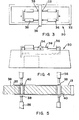
- Apparatus for initially punching access holes in the walls of a tubular element 13 from which the tubular member 12 is formed is shown particularly in Fi- g ures 3 to 5 and is generally indicated by reference numeral 30.
- the apparatus 30 includes a base 32 with respect to which an elongate first support member 34 is securely located to project transversely across the base.
- Two pairs of hydraulic jacks 36 are provided on opposite sides of the first support member 34, the hydraulic jacks 36 being positioned and adapted for displacing punching tools 38 towards one another, radially with respect to a longitudinal axis of the support member 34, in the manner hereinafter described.
- the first support member 34 has two punching dies 40 secured therein which are aligned with the punching tools 38.
- the tubular element 13 is positioned on the first support member 34, being snugly receivable thereon.
- the exact location of the tubular element 13 on the first support member 34 is defined by a stop 35 and when so positioned, the hydraulic jacks 36 are hydraulically actuated to displace the punching tools 38 towards the punching dies 40 thereby punching two pairs of opposed access apertures 42 in the wall of the tubular element 13.
- the configuration of these apertures 42 is oval as is shown clearly in Figure 6, this being ne- cessar y for an even spread of material during the extrusion process which is to follow.
- the tubular element 13 can be removed from the first support member 34 to be positioned on a similar second support member 44 of an apparatus which is partially shown in Figure 7 and which is generally indicated by reference numeral 46.
- the apparatus 46 is generally of a similar configuraton to the apparatus 30 insofar as the support member 44 is generally the equivalent of the support member 34 and two pairs of opposed jacks are also provided in a similar configuration to the jacks 36.
- the support member 4a houses two formina tools 48 which are radially displaceable with respect to the support member 44.
- the tubular element 13 is located on the support member 44 such that the forming tools 48 are aligned with the apertures 42. It will be appreciated that only one forming tool 48 is shown whereas the apparatus 46 in fact includes two such forming tools.
- a split die 50 surrounds the tubular element 13 when located on the support member 44, the die 50 defining extrusion formations 28 defining the receiving apertures 14. Passages 34 extend through the die 50 and terminate in the formations 52 as shown clearly in Figure 7.
- Each pair of lacks includes displacement tools 56 which are able to pass through the passages 54 within the die 50 as well as the access apertures 42 so that they are engageable with their associated forming tool 48 as shown, thereby effectively also locating this tool 48.
- the forming tool 48 In use, in order to extrude the lip formations 28, the forming tool 48 is initially displaced in one direction by one of the tools 56, the other tool 56 being displaced in the opposite direction.
- the forming tool 48 engages the tubular element 13 in the region of one access aperture 42 causing deformation of this re- qion of the element 13 to form the lip formation 2R which in turn defines the receiving aperture 14.
- the forming tool 48 is displaced until the lip formation 28 is completely formed whereafter the direction of displacement is reversed to thereby cause deformation of the opposite region of the tubular element 13 to form the opposed lip formation 25.
- the two forming tools 48 can be displaced simultaneously by proper synchronisation of the hydraulic jacks.
- opposed hydraulic jacks are hydraulically connected together so that when hydraulic liquid is charged into one jack to cause effective extension thereof hydraulic liquid is discharged from the opposed jack causing retraction of the displacement tool thereof.
- tubular member 12 having the receiving apertures 14 formed therein can be removed from the second support member 44 whereafter the end cap 18 and the base plate 20 are secured thereto.
- Stanchions 10 manufactured in accordance with the method above-described and utilising the punching apparatus 30 and the extrusion apparatus 46 can conve- nientl y be manufactured of materials such as stainless steel since no heating is required which may cause discolouring thereof. Finishing and polishing of the product after its manufacture is thus not required. Any alternative materials can also be used as may be required.
- the above method and apparatus can also be used for stanchions which are to support handrailing at an angle to a horizontal surface, the configuration of the dies 50 of the extrusion apparatus 46 being suitably adapted for this purpose. It will be appreciated that the dies 50 are suitably angled and the position of the apertures 42 is suitably adjusted. Also, the forming tool 48 will be displaced at a suitable angle.
- stainless steel may be utilised to form stanchions, resulting in a cheap, strong, longlasting maintenance free, corrosive resistant product.
Landscapes
- Engineering & Computer Science (AREA)
- Architecture (AREA)
- Mechanical Engineering (AREA)
- Civil Engineering (AREA)
- Structural Engineering (AREA)
- Steps, Ramps, And Handrails (AREA)
- Ladders (AREA)
- Fencing (AREA)
Applications Claiming Priority (2)
| Application Number | Priority Date | Filing Date | Title |
|---|---|---|---|
| ZA833210 | 1983-05-05 | ||
| ZA833210 | 1983-05-05 |
Publications (1)
| Publication Number | Publication Date |
|---|---|
| EP0124902A1 true EP0124902A1 (de) | 1984-11-14 |
Family
ID=25576695
Family Applications (1)
| Application Number | Title | Priority Date | Filing Date |
|---|---|---|---|
| EP84105157A Withdrawn EP0124902A1 (de) | 1983-05-05 | 1984-05-07 | Verfahren und Vorrichtung zur Herstellung von Streben |
Country Status (4)
| Country | Link |
|---|---|
| EP (1) | EP0124902A1 (de) |
| JP (1) | JPS6076222A (de) |
| AU (1) | AU2771084A (de) |
| ES (1) | ES8503534A1 (de) |
Cited By (2)
| Publication number | Priority date | Publication date | Assignee | Title |
|---|---|---|---|---|
| FR2591681A1 (fr) * | 1985-12-16 | 1987-06-19 | Lippis Mario | Hidronervure |
| EP0562678A1 (de) * | 1992-03-26 | 1993-09-29 | De Boer Stalinrichtingen B.V. | Vorrichtung und Verfahren zur Endlagendämpfung |
Citations (3)
| Publication number | Priority date | Publication date | Assignee | Title |
|---|---|---|---|---|
| DE2747166A1 (de) * | 1976-11-01 | 1978-05-11 | Grove Valve & Regulator Co | Verfahren zum fliesspressen zylindrischer seitlicher ansaetze an ein rohrfoermiges glied mit mindestens einer seitlichen oeffnung |
| WO1982002569A1 (en) * | 1981-01-22 | 1982-08-05 | Timo Ilmari Rautakoura | Supporting tube for a tube construction and its manufacturing procedure |
| DD205347A1 (de) * | 1982-01-27 | 1983-12-28 | Siegfried Schliemann | Vorrichtung zum stanzen von langloechern in stahlrohren |
-
1984
- 1984-05-04 ES ES532224A patent/ES8503534A1/es not_active Expired
- 1984-05-04 AU AU27710/84A patent/AU2771084A/en not_active Abandoned
- 1984-05-07 EP EP84105157A patent/EP0124902A1/de not_active Withdrawn
- 1984-05-07 JP JP59091696A patent/JPS6076222A/ja active Pending
Patent Citations (3)
| Publication number | Priority date | Publication date | Assignee | Title |
|---|---|---|---|---|
| DE2747166A1 (de) * | 1976-11-01 | 1978-05-11 | Grove Valve & Regulator Co | Verfahren zum fliesspressen zylindrischer seitlicher ansaetze an ein rohrfoermiges glied mit mindestens einer seitlichen oeffnung |
| WO1982002569A1 (en) * | 1981-01-22 | 1982-08-05 | Timo Ilmari Rautakoura | Supporting tube for a tube construction and its manufacturing procedure |
| DD205347A1 (de) * | 1982-01-27 | 1983-12-28 | Siegfried Schliemann | Vorrichtung zum stanzen von langloechern in stahlrohren |
Cited By (2)
| Publication number | Priority date | Publication date | Assignee | Title |
|---|---|---|---|---|
| FR2591681A1 (fr) * | 1985-12-16 | 1987-06-19 | Lippis Mario | Hidronervure |
| EP0562678A1 (de) * | 1992-03-26 | 1993-09-29 | De Boer Stalinrichtingen B.V. | Vorrichtung und Verfahren zur Endlagendämpfung |
Also Published As
| Publication number | Publication date |
|---|---|
| ES532224A0 (es) | 1985-03-01 |
| JPS6076222A (ja) | 1985-04-30 |
| ES8503534A1 (es) | 1985-03-01 |
| AU2771084A (en) | 1984-11-08 |
Similar Documents
| Publication | Publication Date | Title |
|---|---|---|
| US5673585A (en) | Automated dimpling apparatus | |
| CA1055279A (en) | Method for forming counter-sunk hole in a base material and an apparatus for carrying out the same | |
| DE2617530C3 (de) | Verfahren und Vorrichtung zum Herstellen von Behältern aus thermoplastischem Schaumkunststoff | |
| US3599318A (en) | Method of bonding sheets | |
| US8215597B1 (en) | Electrical box support tab construction | |
| EP0124902A1 (de) | Verfahren und Vorrichtung zur Herstellung von Streben | |
| US3180196A (en) | Apparatus for shearing the ends of a tubular member | |
| US3557600A (en) | Transfer press | |
| JP2807952B2 (ja) | ワークのプレス装置 | |
| GB2072057A (en) | Method for manufacture of electric contact | |
| DE2029896A1 (de) | ||
| US2284956A (en) | Die insert | |
| JPH08206750A (ja) | プレス孔明け装置 | |
| US2858884A (en) | Blanking sheet material | |
| GB2039234A (en) | Manufacture of a brake shoe assembly | |
| US4429560A (en) | Apparatus for making a transition plate for a mine roof truss | |
| CN220611764U (zh) | 一种空心异形铝型材挤压模具 | |
| JPS628252B2 (de) | ||
| CN222919532U (zh) | 一种抱箍冲压工装 | |
| RU2011465C1 (ru) | Устройство для осадки осесимметричных заготовок | |
| US3009504A (en) | Apparatus for making brick cases | |
| EP1017517B1 (de) | Verfahren zum stanzen und stanzvorrichtung | |
| SU893285A1 (ru) | Штамп дл изготовлени тройников из листовых заготовок | |
| SU1266630A1 (ru) | Устройство дл ковки заготовок прот жкой | |
| JPS6030980Y2 (ja) | プレス金型によるフツク部品の曲げ装置 |
Legal Events
| Date | Code | Title | Description |
|---|---|---|---|
| PUAI | Public reference made under article 153(3) epc to a published international application that has entered the european phase |
Free format text: ORIGINAL CODE: 0009012 |
|
| AK | Designated contracting states |
Designated state(s): AT BE CH DE FR GB IT LI LU NL SE |
|
| 17P | Request for examination filed |
Effective date: 19850509 |
|
| STAA | Information on the status of an ep patent application or granted ep patent |
Free format text: STATUS: THE APPLICATION IS DEEMED TO BE WITHDRAWN |
|
| 18D | Application deemed to be withdrawn |
Effective date: 19861130 |