EP0124902A1 - A method of and an apparatus for manufacturing stanchions - Google Patents
A method of and an apparatus for manufacturing stanchions Download PDFInfo
- Publication number
- EP0124902A1 EP0124902A1 EP84105157A EP84105157A EP0124902A1 EP 0124902 A1 EP0124902 A1 EP 0124902A1 EP 84105157 A EP84105157 A EP 84105157A EP 84105157 A EP84105157 A EP 84105157A EP 0124902 A1 EP0124902 A1 EP 0124902A1
- Authority
- EP
- European Patent Office
- Prior art keywords
- access
- tubular element
- forming
- aperture
- forming tool
- Prior art date
- Legal status (The legal status is an assumption and is not a legal conclusion. Google has not performed a legal analysis and makes no representation as to the accuracy of the status listed.)
- Withdrawn
Links
Images


Classifications
-
- E—FIXED CONSTRUCTIONS
- E04—BUILDING
- E04F—FINISHING WORK ON BUILDINGS, e.g. STAIRS, FLOORS
- E04F11/00—Stairways, ramps, or like structures; Balustrades; Handrails
- E04F11/18—Balustrades; Handrails
- E04F11/181—Balustrades
-
- B—PERFORMING OPERATIONS; TRANSPORTING
- B21—MECHANICAL METAL-WORKING WITHOUT ESSENTIALLY REMOVING MATERIAL; PUNCHING METAL
- B21D—WORKING OR PROCESSING OF SHEET METAL OR METAL TUBES, RODS OR PROFILES WITHOUT ESSENTIALLY REMOVING MATERIAL; PUNCHING METAL
- B21D39/00—Application of procedures in order to connect objects or parts, e.g. coating with sheet metal otherwise than by plating; Tube expanders
- B21D39/04—Application of procedures in order to connect objects or parts, e.g. coating with sheet metal otherwise than by plating; Tube expanders of tubes with tubes; of tubes with rods
- B21D39/044—Application of procedures in order to connect objects or parts, e.g. coating with sheet metal otherwise than by plating; Tube expanders of tubes with tubes; of tubes with rods perpendicular
Definitions
- THIS INVENTION relates to the manufacture of stanchions for handrailing, or the like. More particularly, the invention relates to a method of and an apparatus for manufacturing stanchions for handrailing, or the like.
- a method of manufacturing from an elongate tubular element a stanchion for handrailing which includes deforming material of the tubular element from within the element to form an outwardly projecting li p formation which defines a receiving aperture, in which a handrail is receivable.
- an apparatus for manufacturing from an elongate tubular element, a stanchion for handrailing which includes a deforming means for deforming material of the tubular element from within the element to form an outwardly projecting li p formation which defines a receiving aperture, in which a handrail is receivable.
- An access aperture may first be formed in the tubular element and a forming tool may then be located in the element in alignment with the access aperture. The forming tool may then be displaced, via the access aperture, to deform the tubular element.
- the apparatus may include an access aperture forming means for forming the access aperture and the deforming means may include a forming tool which is locatable in the element in alignment with the access aperture and a displacing means engageable with the forming tool via the access aperture to displace the forming tool and deform the element.
- a pair of opposed access apertures may be formed and the forming tool may then be displaced towards one of the access apertures and then the other to deform material thereabout to form the lip formations.
- This may be effected by pushing the forming tool towards one access aperture by means of a displacing tool which passes through the other access aperture and engages the forming tool.
- the forminq tool mav have seats at opposed ends in which the displacing tool is received.
- the deforming means may also include a die which is located externally of the element and cooperates with the forming tool to form the lip formations.
- a punching die may be provided which is locatable within the element to assist in the formation of the access apertures.
- the punching die and the forming tool are carried by suitable support members that are receivable within the tubular element.
- the access apertures may have an oval shape, having a longer axis that is aligned with a longitudinal axis of the tubular element.
- a stanchion in accordance with the present invention, may be manufactured of any suitable metal or like material and, in particular, may be manufactured of stainless steel.
- the method of manufacture suits the use of stainless steel, as the method of manufacture does not use exessive heating or welding which would discolour stainless steel.
- a stanchion in accordance with the invention, is generally indicated by reference numeral 10.
- the stanchion 10 includes an elongate tubular member 12 having opposed receiving apertures 14 formed therein within which handrails 16 are received and supported.
- An end cap 18 is located on the top end of the tubular member 12, and a baseplate 20 is located at the opposite base end of the tubular member 12.
- the end cap 18 is formed by a pressing process from a sheet and defines an engaging formation which frictionally engages the top end of the tubular element 12.
- the end cap 18 is heated and/or the member 12 is cooled causing expansion and/or shrinkage respectively to permit engagement of the end cap 18 and the tubular member 12, these items then being allowed to cool and heat up to provide a secure shrink fit therebetween.
- the base plate 20 is also formed by a pressing process from a sheet, the base plate 20 being of a rectangular configuration and defining a receiving socket 24 within which the tubular member 12 is frictionally located.
- the member 12 and the base plate 20 may also be secured together by a shrink fit.
- the base plate 20 defines a number of apertures 26 therein through which bolts, screws, or the like can pass to fix the base plate and thus the tubular member 12 on a support surface such as a floor, or the like. In this way, the complete stanchion 10 can be mounted where handrailing is required.
- the receiving apertures 14 for the handrails 16 are formed by means of a punching and extrusion process which is particularly adapted to define these apertures within the tubular member 12 without causing regions of weakness within the member 12. More particularly, the apertures 14 are defined by lip formations 28 which define and surround these apertures.
- Apparatus for initially punching access holes in the walls of a tubular element 13 from which the tubular member 12 is formed is shown particularly in Fi- g ures 3 to 5 and is generally indicated by reference numeral 30.
- the apparatus 30 includes a base 32 with respect to which an elongate first support member 34 is securely located to project transversely across the base.
- Two pairs of hydraulic jacks 36 are provided on opposite sides of the first support member 34, the hydraulic jacks 36 being positioned and adapted for displacing punching tools 38 towards one another, radially with respect to a longitudinal axis of the support member 34, in the manner hereinafter described.
- the first support member 34 has two punching dies 40 secured therein which are aligned with the punching tools 38.
- the tubular element 13 is positioned on the first support member 34, being snugly receivable thereon.
- the exact location of the tubular element 13 on the first support member 34 is defined by a stop 35 and when so positioned, the hydraulic jacks 36 are hydraulically actuated to displace the punching tools 38 towards the punching dies 40 thereby punching two pairs of opposed access apertures 42 in the wall of the tubular element 13.
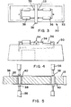
- the configuration of these apertures 42 is oval as is shown clearly in Figure 6, this being ne- cessar y for an even spread of material during the extrusion process which is to follow.
- the tubular element 13 can be removed from the first support member 34 to be positioned on a similar second support member 44 of an apparatus which is partially shown in Figure 7 and which is generally indicated by reference numeral 46.
- the apparatus 46 is generally of a similar configuraton to the apparatus 30 insofar as the support member 44 is generally the equivalent of the support member 34 and two pairs of opposed jacks are also provided in a similar configuration to the jacks 36.
- the support member 4a houses two formina tools 48 which are radially displaceable with respect to the support member 44.
- the tubular element 13 is located on the support member 44 such that the forming tools 48 are aligned with the apertures 42. It will be appreciated that only one forming tool 48 is shown whereas the apparatus 46 in fact includes two such forming tools.
- a split die 50 surrounds the tubular element 13 when located on the support member 44, the die 50 defining extrusion formations 28 defining the receiving apertures 14. Passages 34 extend through the die 50 and terminate in the formations 52 as shown clearly in Figure 7.
- Each pair of lacks includes displacement tools 56 which are able to pass through the passages 54 within the die 50 as well as the access apertures 42 so that they are engageable with their associated forming tool 48 as shown, thereby effectively also locating this tool 48.
- the forming tool 48 In use, in order to extrude the lip formations 28, the forming tool 48 is initially displaced in one direction by one of the tools 56, the other tool 56 being displaced in the opposite direction.
- the forming tool 48 engages the tubular element 13 in the region of one access aperture 42 causing deformation of this re- qion of the element 13 to form the lip formation 2R which in turn defines the receiving aperture 14.
- the forming tool 48 is displaced until the lip formation 28 is completely formed whereafter the direction of displacement is reversed to thereby cause deformation of the opposite region of the tubular element 13 to form the opposed lip formation 25.
- the two forming tools 48 can be displaced simultaneously by proper synchronisation of the hydraulic jacks.
- opposed hydraulic jacks are hydraulically connected together so that when hydraulic liquid is charged into one jack to cause effective extension thereof hydraulic liquid is discharged from the opposed jack causing retraction of the displacement tool thereof.
- tubular member 12 having the receiving apertures 14 formed therein can be removed from the second support member 44 whereafter the end cap 18 and the base plate 20 are secured thereto.
- Stanchions 10 manufactured in accordance with the method above-described and utilising the punching apparatus 30 and the extrusion apparatus 46 can conve- nientl y be manufactured of materials such as stainless steel since no heating is required which may cause discolouring thereof. Finishing and polishing of the product after its manufacture is thus not required. Any alternative materials can also be used as may be required.
- the above method and apparatus can also be used for stanchions which are to support handrailing at an angle to a horizontal surface, the configuration of the dies 50 of the extrusion apparatus 46 being suitably adapted for this purpose. It will be appreciated that the dies 50 are suitably angled and the position of the apertures 42 is suitably adjusted. Also, the forming tool 48 will be displaced at a suitable angle.
- stainless steel may be utilised to form stanchions, resulting in a cheap, strong, longlasting maintenance free, corrosive resistant product.
Abstract
A stainless steel stanchion (10) is formed from a tubular element (12). Two pairs of opposed access apertures are punched in the tubular element (12). Two forming tools are located in the tubular element (12), each in alignment with one of the pairs of access apertures. The forming tools are then displaced by displacement tools which engage the forming tools via the access apertures. The displacement tools push the forming tools first one way and then the other to deform wall material in the region of the access apertures to form outwardly protruding lip formations (28) which define receiving apertures (14) for handrails (16). A base (20) and cap (18) are shrink fitted to the formed tubular member (12)to form the stanchion (10). As there is no heating or welding the stainless steel does not discolour.
Description
- THIS INVENTION relates to the manufacture of stanchions for handrailing, or the like. More particularly, the invention relates to a method of and an apparatus for manufacturing stanchions for handrailing, or the like.
- According to the invention there is provided a method of manufacturing from an elongate tubular element a stanchion for handrailing, which includes deforming material of the tubular element from within the element to form an outwardly projecting lip formation which defines a receiving aperture, in which a handrail is receivable.
- Further, according to the invention there is provided an apparatus for manufacturing from an elongate tubular element, a stanchion for handrailing, which includes a deforming means for deforming material of the tubular element from within the element to form an outwardly projecting lip formation which defines a receiving aperture, in which a handrail is receivable.
- An access aperture may first be formed in the tubular element and a forming tool may then be located in the element in alignment with the access aperture. The forming tool may then be displaced, via the access aperture, to deform the tubular element. Thus, the apparatus mav include an access aperture forming means for forming the access aperture and the deforming means may include a forming tool which is locatable in the element in alignment with the access aperture and a displacing means engageable with the forming tool via the access aperture to displace the forming tool and deform the element.
- Conveniently, a pair of opposed access apertures may be formed and the forming tool may then be displaced towards one of the access apertures and then the other to deform material thereabout to form the lip formations. This may be effected by pushing the forming tool towards one access aperture by means of a displacing tool which passes through the other access aperture and engages the forming tool. To facilitate engagement of the displacing tool with the forming tool, the forminq tool mav have seats at opposed ends in which the displacing tool is received.
- The deforming means may also include a die which is located externally of the element and cooperates with the forming tool to form the lip formations. Similarly, a punching die may be provided which is locatable within the element to assist in the formation of the access apertures.
- It will be appreciated that the punching die and the forming tool are carried by suitable support members that are receivable within the tubular element.
- In order to ensure that there is an even spread of material when the lip formations are formed the access apertures may have an oval shape, having a longer axis that is aligned with a longitudinal axis of the tubular element.
- A stanchion, in accordance with the present invention, may be manufactured of any suitable metal or like material and, in particular, may be manufactured of stainless steel. The method of manufacture suits the use of stainless steel, as the method of manufacture does not use exessive heating or welding which would discolour stainless steel.
- The invention is now described, by way of an example, with reference to the accompanying diaarammatic drawings, in which:
- Figure 1 shows a stanchion in accordance with the invention with handrails engaged therewith;
- Figure 2 shows a cross-sectional side view of the stanchion of Figure 1;
- Figure 3 shows a plan view of an apparatus for pun- china holes in tubular elements;
- Figure 4 shows a side view of the apparatus of Figure 3;
- Figure 5 shows a detailed view of a part of the apparatus of Figure 3, in use;
- Figure 6 shows a hole punched in a tubular element utilising the apparatus of Figure 3; and
- Figure 7 shows a schematic cross-sectional view of an apparatus for deforming material of a tubular element from within in accordance with the invention.
- Referring initially to Figures 1 and 2 of the drawings, a stanchion, in accordance with the invention, is generally indicated by
reference numeral 10. Thestanchion 10 includes an elongatetubular member 12 having opposed receivingapertures 14 formed therein within whichhandrails 16 are received and supported. Anend cap 18 is located on the top end of thetubular member 12, and abaseplate 20 is located at the opposite base end of thetubular member 12. - The
end cap 18 is formed by a pressing process from a sheet and defines an engaging formation which frictionally engages the top end of thetubular element 12. Theend cap 18 is heated and/or themember 12 is cooled causing expansion and/or shrinkage respectively to permit engagement of theend cap 18 and thetubular member 12, these items then being allowed to cool and heat up to provide a secure shrink fit therebetween. - The
base plate 20 is also formed by a pressing process from a sheet, thebase plate 20 being of a rectangular configuration and defining a receiving socket 24 within which thetubular member 12 is frictionally located. Themember 12 and thebase plate 20 may also be secured together by a shrink fit. Furthermore, thebase plate 20 defines a number ofapertures 26 therein through which bolts, screws, or the like can pass to fix the base plate and thus thetubular member 12 on a support surface such as a floor, or the like. In this way, thecomplete stanchion 10 can be mounted where handrailing is required. - The receiving
apertures 14 for thehandrails 16 are formed by means of a punching and extrusion process which is particularly adapted to define these apertures within thetubular member 12 without causing regions of weakness within themember 12. More particularly, theapertures 14 are defined bylip formations 28 which define and surround these apertures. - Apparatus for initially punching access holes in the walls of a
tubular element 13 from which thetubular member 12 is formed is shown particularly in Fi- gures 3 to 5 and is generally indicated byreference numeral 30. Theapparatus 30 includes abase 32 with respect to which an elongatefirst support member 34 is securely located to project transversely across the base. Two pairs ofhydraulic jacks 36 are provided on opposite sides of thefirst support member 34, thehydraulic jacks 36 being positioned and adapted for displacingpunching tools 38 towards one another, radially with respect to a longitudinal axis of thesupport member 34, in the manner hereinafter described. - The
first support member 34 has two punching dies 40 secured therein which are aligned with thepunching tools 38. - In use, the
tubular element 13 is positioned on thefirst support member 34, being snugly receivable thereon. The exact location of thetubular element 13 on thefirst support member 34 is defined by astop 35 and when so positioned, thehydraulic jacks 36 are hydraulically actuated to displace thepunching tools 38 towards thepunching dies 40 thereby punching two pairs ofopposed access apertures 42 in the wall of thetubular element 13. The configuration of theseapertures 42 is oval as is shown clearly in Figure 6, this being ne- cessary for an even spread of material during the extrusion process which is to follow. - It will be appreciated that all the
hydraulic jacks 36 are simultaneously actuated so that theapertures 42 are simultaneously punched and after thepunching tools 38 have been retracted thetubular element 13 can be removed from thefirst support member 34 to be positioned on a similarsecond support member 44 of an apparatus which is partially shown in Figure 7 and which is generally indicated byreference numeral 46. Theapparatus 46 is generally of a similar configuraton to theapparatus 30 insofar as thesupport member 44 is generally the equivalent of thesupport member 34 and two pairs of opposed jacks are also provided in a similar configuration to thejacks 36. Instead of the punching dies 40 the support member 4a houses twoformina tools 48 which are radially displaceable with respect to thesupport member 44. Thetubular element 13 is located on thesupport member 44 such that the formingtools 48 are aligned with theapertures 42. It will be appreciated that only one formingtool 48 is shown whereas theapparatus 46 in fact includes two such forming tools. Asplit die 50 surrounds thetubular element 13 when located on thesupport member 44, the die 50 definingextrusion formations 28 defining thereceiving apertures 14.Passages 34 extend through the die 50 and terminate in theformations 52 as shown clearly in Figure 7. - Each pair of lacks (not shown) includes
displacement tools 56 which are able to pass through thepassages 54 within thedie 50 as well as theaccess apertures 42 so that they are engageable with their associated formingtool 48 as shown, thereby effectively also locating thistool 48. - In use, in order to extrude the
lip formations 28, the formingtool 48 is initially displaced in one direction by one of thetools 56, theother tool 56 being displaced in the opposite direction. The formingtool 48 engages thetubular element 13 in the region of oneaccess aperture 42 causing deformation of this re- qion of theelement 13 to form the lip formation 2R which in turn defines thereceiving aperture 14. The formingtool 48 is displaced until thelip formation 28 is completely formed whereafter the direction of displacement is reversed to thereby cause deformation of the opposite region of thetubular element 13 to form the opposed lip formation 25. It will be appreciated that the two formingtools 48 can be displaced simultaneously by proper synchronisation of the hydraulic jacks. It will be appreciated that in this configuration, opposed hydraulic jacks are hydraulically connected together so that when hydraulic liquid is charged into one jack to cause effective extension thereof hydraulic liquid is discharged from the opposed jack causing retraction of the displacement tool thereof. - As a result of the original shape of each
access aperture 42, the extrusion operation as above-described provides for the even spread of material when forming thelips 28 thus ensuring that no material weaknesses result. In fact, the regions where theselips 28 are provided are in fact effectively reinforced by the lips and, as such, no weaknesses result along the length of thetubular member 12. - After completion of the extrusion process, the
tubular member 12 having the receivingapertures 14 formed therein can be removed from thesecond support member 44 whereafter theend cap 18 and thebase plate 20 are secured thereto. - Stanchions 10 manufactured in accordance with the method above-described and utilising the
punching apparatus 30 and theextrusion apparatus 46 can conve- niently be manufactured of materials such as stainless steel since no heating is required which may cause discolouring thereof. Finishing and polishing of the product after its manufacture is thus not required. Any alternative materials can also be used as may be required. - It will be appreciated that the above method and apparatus can also be used for stanchions which are to support handrailing at an angle to a horizontal surface, the configuration of the
dies 50 of theextrusion apparatus 46 being suitably adapted for this purpose. It will be appreciated that thedies 50 are suitably angled and the position of theapertures 42 is suitably adjusted. Also, the formingtool 48 will be displaced at a suitable angle. - As the invention does not utilise heat, stainless steel may be utilised to form stanchions, resulting in a cheap, strong, longlasting maintenance free, corrosive resistant product.
Claims (11)
1. A method of manufacturing from an elongate tubular element, a stanchion for handrailing, which includes deforming material of the tubular element from within the element to form an outwardly projecting lip formation which defines a receiving aperture in which a handrail is receivable.
2. The method as claimed in Claim 1, which includes first forming an access aperture in the tubular element locating a forming tool in the element in alignment with the access aperture and displacing the forming tool via the access aperture to deform the tubular element.
3. The method as claimed in Claim 1, which includes forming a pair of opposed access apertures in the tubular element, locating a forming tool within the element in alignment with the access apertures and displacing the forminq tool towards one access aperture and then the other to outwardly deform material about the access apertures to form radially opposed outwardly projecting lip formations which each define a receiving aperture.
4. The method as claimed in Claim 3, in which the forming tool is pushed towards one access aperture by means of a displacing tool which passes through the other aperture and engages the forming tool.
5. The method as claimed in Claim 2, in which an oval access aperture is formed in the tubular element with its longer axis being aligned with a longitudinal axis of the element.
6. An apparatus for manufacturing from an elongate tubular element a stanchion for handrailing which includes a deforming means for deforming material of the tubular element from within the element to form an outwardly projecting lip formation which defines a receiving aperture in which a handrail is receivable.
7. The apparatus as claimed in Claim 6, which includes an access aperture forming means for first forming an access aperture in the tubular element and the deforming means includes a forming tool locatable in the element in alignment with the access aperture and a displacing means engageable with the forming tool via the access aperture to displace the forming tool and deform the element.
8. The apparatus as claimed in Claim 6, which includes an access aperture forming means for forming a pair of opposed access apertures in the tubular element and the deforming means includes a forming tool locatable within the element in alignment with the access apertures and a displacing means for displacing the forming tool towards one access aperture and then the other to outwardly deform material about the access apertures to form radially opposed outwardly projecting lip formations which each define a receiving aperture.
9. The apparatus as claimed in Claim 8, in which the displacing means includes a displacing tool which is able to pass through one of the access apertures and engage the forming tool and is adapted to push the forming tool towards the other access aperture to deform the material thereabout.
10. The apparatus as claimed in Claim 7, in which the access aperture forming means is adapted to form an oval aperture having a longer axis that is aligned with a longitudinal axis of the tubular element.
11. The apparatus as claimed in Claim 9, in which the forming tool has a seat in which the displacing tool is received.
Applications Claiming Priority (2)
| Application Number | Priority Date | Filing Date | Title |
|---|---|---|---|
| ZA833210 | 1983-05-05 | ||
| ZA833210 | 1983-05-05 |
Publications (1)
| Publication Number | Publication Date |
|---|---|
| EP0124902A1 true EP0124902A1 (en) | 1984-11-14 |
Family
ID=25576695
Family Applications (1)
| Application Number | Title | Priority Date | Filing Date |
|---|---|---|---|
| EP84105157A Withdrawn EP0124902A1 (en) | 1983-05-05 | 1984-05-07 | A method of and an apparatus for manufacturing stanchions |
Country Status (4)
| Country | Link |
|---|---|
| EP (1) | EP0124902A1 (en) |
| JP (1) | JPS6076222A (en) |
| AU (1) | AU2771084A (en) |
| ES (1) | ES532224A0 (en) |
Cited By (2)
| Publication number | Priority date | Publication date | Assignee | Title |
|---|---|---|---|---|
| FR2591681A1 (en) * | 1985-12-16 | 1987-06-19 | Lippis Mario | Hydrorib |
| EP0562678A1 (en) * | 1992-03-26 | 1993-09-29 | De Boer Stalinrichtingen B.V. | Stroke damping and method for making said damping |
Citations (3)
| Publication number | Priority date | Publication date | Assignee | Title |
|---|---|---|---|---|
| DE2747166A1 (en) * | 1976-11-01 | 1978-05-11 | Grove Valve & Regulator Co | PROCESS FOR EXTRUDING CYLINDRICAL LATERAL APPARATUS ON A TUBE-SHAPED MEMBER WITH AT LEAST ONE LATERAL OPENING |
| WO1982002569A1 (en) * | 1981-01-22 | 1982-08-05 | Timo Ilmari Rautakoura | Supporting tube for a tube construction and its manufacturing procedure |
| DD205347A1 (en) * | 1982-01-27 | 1983-12-28 | Siegfried Schliemann | DEVICE FOR PUNCHING LANGLOECHERS IN STEEL TUBES |
-
1984
- 1984-05-04 AU AU27710/84A patent/AU2771084A/en not_active Abandoned
- 1984-05-04 ES ES532224A patent/ES532224A0/en active Granted
- 1984-05-07 JP JP59091696A patent/JPS6076222A/en active Pending
- 1984-05-07 EP EP84105157A patent/EP0124902A1/en not_active Withdrawn
Patent Citations (3)
| Publication number | Priority date | Publication date | Assignee | Title |
|---|---|---|---|---|
| DE2747166A1 (en) * | 1976-11-01 | 1978-05-11 | Grove Valve & Regulator Co | PROCESS FOR EXTRUDING CYLINDRICAL LATERAL APPARATUS ON A TUBE-SHAPED MEMBER WITH AT LEAST ONE LATERAL OPENING |
| WO1982002569A1 (en) * | 1981-01-22 | 1982-08-05 | Timo Ilmari Rautakoura | Supporting tube for a tube construction and its manufacturing procedure |
| DD205347A1 (en) * | 1982-01-27 | 1983-12-28 | Siegfried Schliemann | DEVICE FOR PUNCHING LANGLOECHERS IN STEEL TUBES |
Cited By (2)
| Publication number | Priority date | Publication date | Assignee | Title |
|---|---|---|---|---|
| FR2591681A1 (en) * | 1985-12-16 | 1987-06-19 | Lippis Mario | Hydrorib |
| EP0562678A1 (en) * | 1992-03-26 | 1993-09-29 | De Boer Stalinrichtingen B.V. | Stroke damping and method for making said damping |
Also Published As
| Publication number | Publication date |
|---|---|
| ES8503534A1 (en) | 1985-03-01 |
| AU2771084A (en) | 1984-11-08 |
| JPS6076222A (en) | 1985-04-30 |
| ES532224A0 (en) | 1985-03-01 |
Similar Documents
| Publication | Publication Date | Title |
|---|---|---|
| US5673585A (en) | Automated dimpling apparatus | |
| US3599318A (en) | Method of bonding sheets | |
| DE69913646T2 (en) | Device for high pressure molding and high pressure cutting | |
| EP1117496B1 (en) | Fluid form | |
| US8215597B1 (en) | Electrical box support tab construction | |
| EP0124902A1 (en) | A method of and an apparatus for manufacturing stanchions | |
| US3180196A (en) | Apparatus for shearing the ends of a tubular member | |
| GB2072057A (en) | Method for manufacture of electric contact | |
| JP2807952B2 (en) | Work press equipment | |
| DE2029896A1 (en) | ||
| US2284956A (en) | Die insert | |
| US2858884A (en) | Blanking sheet material | |
| CN220611764U (en) | Hollow special-shaped aluminum profile extrusion die | |
| GB2039234A (en) | Manufacture of a brake shoe assembly | |
| JPS6320612B2 (en) | ||
| JPS628252B2 (en) | ||
| JPS5832017B2 (en) | Piston heading method in Homer | |
| CN114619221B (en) | Scissor assembly method and hybrid scissor assembly machine | |
| JPH04370492A (en) | Manifold and manufacture thereof | |
| CN214768134U (en) | Stamping equipment for alloy steel forming | |
| CN210334119U (en) | Hook processing equipment | |
| US3009504A (en) | Apparatus for making brick cases | |
| SU1266630A1 (en) | Arrangement for forging billets by broaching | |
| RU2011465C1 (en) | Device for swaging axisymmetric workpieces | |
| JP3014667B2 (en) | Handrail and its processing equipment |
Legal Events
| Date | Code | Title | Description |
|---|---|---|---|
| PUAI | Public reference made under article 153(3) epc to a published international application that has entered the european phase |
Free format text: ORIGINAL CODE: 0009012 |
|
| AK | Designated contracting states |
Designated state(s): AT BE CH DE FR GB IT LI LU NL SE |
|
| 17P | Request for examination filed |
Effective date: 19850509 |
|
| STAA | Information on the status of an ep patent application or granted ep patent |
Free format text: STATUS: THE APPLICATION IS DEEMED TO BE WITHDRAWN |
|
| 18D | Application deemed to be withdrawn |
Effective date: 19861130 |