EP0122995A1 - Renforcement d'une masse - Google Patents
Renforcement d'une masse Download PDFInfo
- Publication number
- EP0122995A1 EP0122995A1 EP83305982A EP83305982A EP0122995A1 EP 0122995 A1 EP0122995 A1 EP 0122995A1 EP 83305982 A EP83305982 A EP 83305982A EP 83305982 A EP83305982 A EP 83305982A EP 0122995 A1 EP0122995 A1 EP 0122995A1
- Authority
- EP
- European Patent Office
- Prior art keywords
- pieces
- matrix
- piece
- mesh
- soil
- Prior art date
- Legal status (The legal status is an assumption and is not a legal conclusion. Google has not performed a legal analysis and makes no representation as to the accuracy of the status listed.)
- Granted
Links
Images


Classifications
-
- E—FIXED CONSTRUCTIONS
- E02—HYDRAULIC ENGINEERING; FOUNDATIONS; SOIL SHIFTING
- E02D—FOUNDATIONS; EXCAVATIONS; EMBANKMENTS; UNDERGROUND OR UNDERWATER STRUCTURES
- E02D3/00—Improving or preserving soil or rock, e.g. preserving permafrost soil
-
- E—FIXED CONSTRUCTIONS
- E01—CONSTRUCTION OF ROADS, RAILWAYS, OR BRIDGES
- E01C—CONSTRUCTION OF, OR SURFACES FOR, ROADS, SPORTS GROUNDS, OR THE LIKE; MACHINES OR AUXILIARY TOOLS FOR CONSTRUCTION OR REPAIR
- E01C11/00—Details of pavings
- E01C11/16—Reinforcements
-
- C—CHEMISTRY; METALLURGY
- C04—CEMENTS; CONCRETE; ARTIFICIAL STONE; CERAMICS; REFRACTORIES
- C04B—LIME, MAGNESIA; SLAG; CEMENTS; COMPOSITIONS THEREOF, e.g. MORTARS, CONCRETE OR LIKE BUILDING MATERIALS; ARTIFICIAL STONE; CERAMICS; REFRACTORIES; TREATMENT OF NATURAL STONE
- C04B16/00—Use of organic materials as fillers, e.g. pigments, for mortars, concrete or artificial stone; Treatment of organic materials specially adapted to enhance their filling properties in mortars, concrete or artificial stone
- C04B16/12—Use of organic materials as fillers, e.g. pigments, for mortars, concrete or artificial stone; Treatment of organic materials specially adapted to enhance their filling properties in mortars, concrete or artificial stone characterised by the shape, e.g. perforated strips
-
- E—FIXED CONSTRUCTIONS
- E02—HYDRAULIC ENGINEERING; FOUNDATIONS; SOIL SHIFTING
- E02D—FOUNDATIONS; EXCAVATIONS; EMBANKMENTS; UNDERGROUND OR UNDERWATER STRUCTURES
- E02D3/00—Improving or preserving soil or rock, e.g. preserving permafrost soil
- E02D3/005—Soil-conditioning by mixing with fibrous materials, filaments, open mesh or the like
-
- E—FIXED CONSTRUCTIONS
- E04—BUILDING
- E04C—STRUCTURAL ELEMENTS; BUILDING MATERIALS
- E04C5/00—Reinforcing elements, e.g. for concrete; Auxiliary elements therefor
- E04C5/07—Reinforcing elements of material other than metal, e.g. of glass, of plastics, or not exclusively made of metal
- E04C5/073—Discrete reinforcing elements, e.g. fibres
Definitions
- the present invention relates to a method of strengthening a particulate matrix, comprising embedding generally flat pieces of flexible, open mesh structure in the matrix.
- the word "strengthening” includes reinforcing and/or stabilizing.
- the matrix can be any particulate matrix, whether load-bearing or not.
- the structures formed can be for instance geotechnical structures, structural components for building, or surfacing materials.
- the maxtrix can be of any suitable form, such as soil (which includes rocks, stones, gravels, sands, clays and the like as well as cement-stabilised soil and cement-bound granular materials (normally containing 2-12% cement), and mine spoil or slag), substances comprising a hydrocarbon binder such as asphalt, bituminous asphalt or tar, substances comprising a hydraulic binder or fill, such as cement, concrete, lean-mix concrete or plaster (which are considered as particulate), substances comprising a pozzolanic binder, and substances comprising a resinous binder, such as chip-board.
- the matrix can be particulate and non-cohesive or cohesive, or inherently substantially rigid: a material such as clay or tar may be viscous and capable of large movement or deformation, or a material such as cement or concrete can be rigid and incapable of large movement or deformation. Particulate matrices will have natural void spaces which can be filled for instance with water and/or air.
- GB 2 073 090A describes a method of strengthening soils in which long and fairly wide lengths of flexible plastics material mesh structure are embedded in the matrix, the lengths being in parallel layers and the lengths being parallel to each other in each layer so as to cover all of the layer.
- the mesh structure has tenaceous junctions or intersections and has high dimensional stability in the plane of the structure. This method is very effective in most applications, but does require skill and care in use, as well as requiring a specially manufactured mesh structure.
- CH 592 219 discloses a method of strengthening cement, tar or bitumen, comprising randomly embedding in the matrix a large number of flexible pieces of plastics material mesh structure without creating a substantial amount of extra void space, each face of each piece having an area which is small relative to the size of the matrix, and each piece comprising more than one mesh opening.
- the pieces are initially supplied in the form of short, twisted cords which are arranged to open or untwist during mixing; mixing must be so timed that the cords have fully untwisted, but have not started to twist or otherwise close up again.
- GB 1 539 898 discloses the use of pieces of steel weld mesh to strengthen concrete, each piece having just one complete mesh.
- the pieces are relatively stiff and each has eight projecting wires, so that there will be a tendency to bridge and form extra void space.
- the present invention provides a method as set forth in Claim 1, a machine as set forth in Claim 22 and strengthening material as set forth in Claim 23.
- the remaining Claims set forth preferred features of the invention.
- rhe pieces of mesh structure provide a positive interlock with the matrix, and thus do not rely entirely on friction between or chemical bonding between the material of the piece and the matrix.
- particles of the matrix in different mesh openings are interlocked together.
- the mesh pieces plus interlocked soil particles form aggregates of particles within the soil mass. Providing there are sufficient mesh pieces, these aggregates will interact so that the whole mass of soil will be interlocked into a single improved mass.
- the effectiveness of the pieces depends upon them having tenaceous junctions or intersections which enables each-piece to interlock effectively with the matrix and properly exploit the strength of the material of the piece without the piece tearing apart.
- each piece has high dimensional stability in the plane of the piece, which enables the piece to withstand forces in its plane and maintain the stability of the matrix.
- asphalts are graded so as to contain particles from a predetermined maximum size down to a fine powder and it is believed that in matrices of the invention, the large particles are anchored by the mesh pieces and the smaller particles are anchored by the larger particles.
- the mesh structure pieces can be easy to manufacture, providing a cheap strengthening.
- the strengthening can be supplied in for instance compact rolls and be cut into the pieces immediately prior to mixing with the matrix.
- the mixing of the pieces with the matrix is random (three-dimensional distribution in a random manner), and the mesh structure pieces would not in general be parallel to each other.
- some pieces may extend in the direction at right angles to the faces as well as parallel to the faces, depending on the thickness of the panel; with thin panels (or sheets), the pieces would be more generally coplanar with the panel.
- the pieces can be incorporated with ease in the matrix without advanced technology and without great skill even though there is a large number of the pieces. Nonetheless, it is surprisingly found that the pieces are highly effective in strengthening the matrix, provided no substantial amount of extra void space is created: for the purposes of this specification, the space occupied by the material of a mesh piece itself is not considered void space - it is desirable, though not essential, that the inclusion of the mesh pieces should not decrease the bulk density of the matrix (plus pieces).
- the incorporation of the mesh pieces can be equivalent to an increase in the overall soil angle of friction of 2° or 3° or by a load spreading effect through the strengthened layer, resulting in an effective increase in the width of the footing.
- soil normally has no significant elastic recovery; soil strengthened with the pieces appears to have some elastic recovery and could be particularly useful for dynamically-loaded locations, such as sub-bases for runways, roads or railways.
- the strengthened soil still has high load bearing capacity and does not heave.
- the pieces can limit movement if cracking occurs and provide some elastic recovery; for instance in cement-stabilised soil, one normally expects a large number of very small cracks to be formed.
- the preferred pieces are of integral plastics material mesh structure comprising molecularly orientated strands.
- Plastics material mesh structures are easy to manufacture and handle. In specific cases such as concrete cladding sheets, the resistance to corrosion is very beneficial. If the method of making the mesh structure is suitably chosen, there can be a large amount of orientation or all zones of each piece can be at least partly orientated or even highly orientated, avoiding wastage of plastics material and also maximizing the tensile strength and modulus of the pieces. In the normal case where the meshes are four-sided and four strands issue from each junction or intersection, the mesh structure is preferably stretched in two directions along the alignments of the strands.
- this can be done by sequential %iaxial stretching, stretching first along the alignment of one set of strands and then along the alignment of the other set of strands; or alternatively by stretching a diamond mesh in a single direction, to stretch all the strands, opening the meshes up laterally, and heat setting the mesh.
- Biaxially orientated structures are preferred as it is easier to achieve dimensional stability.
- any suitable integral plastics material mesh structure can be used, for instance as disclosed in GB 836 555, GB 969 655, GB 1 210 354, GB 1 250 478, GB 1 290 437, GB 2 034 240A or GB 2 035 191B; a deep strand structure such as that of GB 1 210 354 is very suitable because of better anchoring or interlock - the strands are non-circular, being deeper than they are wide.
- HDPE high density polyethylene
- PP polypropylene
- polyesters preferred materials are high density polyethylene (HDPE), polypropylene (PP) or polyesters.
- HDPE or PP can be orientated to a degree corresponding to stretch ratios of 6:1 or more, preferably 10:1 or more; the stretch ratios for polyesters are less, for instance up to about 5:1.
- a suitable high temperature resistant plastics material such as polyester, should be used; the mesh structure may have been heat-set at a temperature of up to for example 230°C.
- materials other than integral plastics material structures can be used, for instance non-metallic or organic-base materials such as resin-bonded open mesh woven structures, a preferred such structure being a Leno weave.
- the material should be non-biodegradable.
- the invention can have significant advantages if used in conjunction with other strengthening in the form of elongate members which extend part way or substantially right through the matrix.
- elongate members may be as disclosed in GB B 1 069 361 (where the elongate members could alternatively be made of fibreglass, for intance with a protective water-impermeable coating), GB 2 035 191B. GB 2 073 090B or GB 2 096 531A.
- the elongate members can be used not only in soil matrices, but also more generally, for instance in matrices comprising hydrocarbon, hydraulic or pozzolanic binders.
- junctions or intersections of the mesh must be tenaceous and should not rupture too easily under tensile forces, in whatever direction the forces are applied to the piece. This is because the pieces will mainly be distributed in the matrix in a multiplicity of directions, i.e. almost totally random. As the matrix is particulate, the effect of the pieces relies on interlock and this could cause splitting of the junctions or intersections even if tensile forces were applied along the axes of the strands, unless the junctions or intersections are tenaceous.
- the expression "tenaceous junctions or interesections” means that the junctions or intersections are not weak and can be stressed in any direction without rupturing too easily. Preferably, if opposed tensile forces are applied across the piece, in whatever direction, the strands rupture (break or split) before the junctions or intersections do so. It is however satisfactory if the tensile strength at break of the junctions or intersections in any direction across the piece and in the plane of the piece is not substantially less than 50% of the average tensile strength at break of the strands; i.e., in practical terms, it is found that the junction or intersection can be weaker than the strands and still perform in a satisfactory manner, though this is not preferred.
- isotropic strength is aimed for under opposed tensile forces in the plane of the piece. This means that the tensile strength at break in any direction across the piece is not substantially less than that in any other direction across the piece, whether break occurs in a strand or at a junction. It is however satisfactory if the tensile strength at break in any direction across the piece (and in the plane of the piece) is not substantially less than 50% of that in any other direction across the piece. In general terms, it is desirable to structure a square or rectangular nesh so that it has substantially equal strengths in the two directions in which the strands extend.
- the mesh pieces will be generally flat prior to mixing or embedding, i.e. at the most just slightly curved due to the curvature of the roll from which they have been produced.
- the pieces will have some flexibility and will not normally lie perfectly flat when embedded in the matrix.
- the pieces should be chosen in relation to the material of the matrix so that they do not create a-substantial amount of extra void space in the matrix. It is found that the mesh pieces can fold over or wrap around to a certain extent during embedding or mixing: a single fold reduces the effective area of a piece, and thus is not desirable, but interlock between the material of the matrix and the pieces still occurs, and no substantial extra void space is created.
- the pieces should have sufficient flexural recovery for a high proportion of them not to become condensed during embedding or mixing, and this is termed "high flexural recovery” herein.
- the flexural recovery can be thought of in terms of the stiffness or springiness of the material of the piece, the material being capable of high bending before yielding. Though it is believed that flexural recovery and/or flexural stiffness are the underlying properties, the actual value of the flexural recovery or stiffness of the mesh pieces need not be taken as the determinative criterion; the length of the piece, the nature of the matrix and the method of embedding are important.
- the material may be chosen so that the piece can be bent through a predetermined angle without excessive plastic deformation, the test being carried out over a short period of time at the temperature of incorporation into the ratrix.
- a suitable standardised flexural recovery test is as follows: four samples 40 x 100 mm are cut, one having its long sides parallel to one set of strands, and the others having their long sides at 45° in each direction and at 90° to those of the first sample. If only smaller specimens are available, the results can be estimated. With the samples horizontal, 60 mm of length are clamped adjacent an edge having a radius of 3 mm so that 40 mm project out over this edge.
- the flexural recovery is the percentage of the original bend angle which is recovered, i.e. if the original droop is a° and the sample returns to a droop of b° (greater than a°), the flexural recovery is 100 x (90 - a)/(90 - b)%.
- a useful practical flexural recovery test is as follows. A sufficiently large sample of the strengthened soil is put into a compaction vessel and compacted to British Standard BS 5930-1981. After compaction, a further 100 mm of the same soil without the mesh pieces is added to cover the surface of the compacted mixture. The sample is then transferred in the vessel to a heated oven where it remains for a time and at a temperature suitable to dry out the sand and heat set the mesh pieces in the form they have taken up during mixing and compaction. After cooling, the mixture is tipped from the vessel onto a metal grid which is then vibrated until substantially all the soil has passed through the grid, leaving the heat-set mesh pieces available for examination. Substantially no mesh pieces should exhibit any substantial degree of rolling, balling, twisting or crumpling. A like test can be carried out for concrete or cement composites, the cement merely being omitted or possibly replaced with very fine sand.
- a convenient strengthened soil sample is required for laboratory work, it can be prepared as follows. Pieces of the mesh structure are progressively added by tumble mixing to a well graded sand (for example, Mid-Ross Sand), which sand contains a percentage moisture content which will ensure ease of mixing - the moisture content can be determined empirically. The mixing is continued until the required percentage of inclusion has been reached. Mixing should then be continued for a further one minute.
- a well graded sand for example, Mid-Ross Sand
- High primary dimensional stability in the plane of the piece means that there is-considerable resistance to elongation when tensile forces are applied across the piece in a direction parallel to a set of strands; this is important.
- High secondary dimensional stability means that there is considerable resistance to the meshes closing up during mixing, particularly when tensile forces are applied across the diagonals of the meshes. If the meshes did close up on mixing, the entry of the matrix material into the meshes would be restricted. It may be important that there is good recovery of the original mesh shape after distortion.
- a useful measure of secondary dimensional stability relates the "distortion load" to the weight of the piece per unit area.
- the distortion load is that tensile force which, when applied across any diagonal of the meshes, reduces the area of the mesh opening by half (related to its unloaded area).
- the distortion load:weight per square metre ratio may be as low as 0.5:1, 0.6:1 or 0.75:1 (ratios below 0.5:1 not being preferred but not being excluded), though preferred minimum values are 1:1, 1.5:1, 2:1, 3:1 or 3.5:1.
- the test should be carried out in the diagonal directions. Normally, if the secondary stability is sufficiently high, the primary stability will be sufficiently high and need not be separately tested.
- the test above can be applied for instance to pieces having very elongate rectangular meshes or having square or nearly square meshes.
- the modified distortion load:weight per square metre ratio is preferably at least 0.6:1 and may be at least 0.8:1 or 1:1, though minimum values of 2:1 or 2.5:1 or more can be realised with some materials.
- the relative density of the material of the pieces of mesh structure may be important, depending on the method of mixing and the consistency of the matrix for instance before setting or consolidation.
- the pieces should remain distributed randomly throughout the matrix, i.e. should not all tend to rise to the top or sink to the bottom.
- the effective tensile modulus of the piece should ideally be similar to that of the matrix if the matrix is rigid, using high modulus structures for matrices such as concrete; however, the invention is still beneficial if the modulus is lower. Low modulus structures can be used for matrices such as soil.
- any matrix there will be a large number of pieces.
- For any particular matrix and mesh piece there will be an optimum number of pieces per unit volume to obtain maximum improvement of properties; this can be determined experimentally.
- the proportion of pieces used will depend upon inter alia the nature of the matrix, particle size distribution in the matrix, strand size, mesh pitch, overall size and shape of pieces, and flexural stiffness and tensile stiffness of the mesh pieces. If the amount of mesh pieces is too great, the mesh pieces will grossly interfere with each other (and may fold) and the matrix/piece interlock action will be suppressed, reducing the strength of the matrix - thus inadequate strength of the individual pieces cannot be compensated for by using a very large amount of the pieces.
- the pieces would provide a self-supporting mass of about the same volume - if, as is normal, strands protrude from the edges of the pieces, the mass can be coherent to a certain extent as protruding strands or even the corner of one piece can engage in the mesh opening of another piece; the effect occurred particularly when using larger mesh pitches.
- the effect was specifically noted when pieces of 18 mm pitch mesh having just four complete mesh openings (2 x 2) were used at 0.5% w/w (dry weight) to strengthen sand.
- a preferred minimum is about 5,000 or 10,000 pieces per cubic metre and a preferred maximum is about 500,000 pieces per cubic metre, though the number depends inter alia on the size of the pieces.
- the proportion w/w of the pieces to the matrix is preferably from about one tenth of that proportion at which the matrix has maximum density to about two and a half times that proportion. All proportions are given herein for dry weight.
- the proportion is preferably less than about 2% or 1% but preferably more than about 0.05%.
- the proportion is preferably as for soil, or may be up to 5%.
- each piece has up to a thousand, five hundred or two hundred and fifty complete mesh openings, the more preferred number being about twenty-five or twenty but for instance eight or nine being possible. It is also possible to operate with pieces having as few as three or four complete mesh openings.
- Each face of a piece will have an area which is small relative to the size of the matrix being strengthened.
- the greatest dimension of the piece would be small relative to the greatest dimension of the matrix, e.g. less than one tenth or one hundredth or one thousandth of the matrix greatest dimension.
- the mesh structure pieces can be quite long, for instance up to 300, 400 or 500 mm long, or even longer. Nonetheless, it is preferred that the pieces be roughly square or at least that the length be of the same order as the breadth, e.g. not more than ten times the breadth and more preferably not more than twice the breadth.
- each face of the pieces is preferably about 10,000 mm 2 or less, the preferred area being about 1,000 mm 2 , for instance 35 mm square or 30 x 40 mm. If however the pieces are long and relatively narrow, each face can have sizes significantly greater than 10,000 mm 2 , for instance up to 20,000 or 3 0, 0 0 0 mm 2 .
- the size of the pieces can be rather larger than for soil, e.g. about 20,000 mm 2 or less.
- the size of the pieces can be as for soil, though much smaller pieces, say down to about 100 mm2 (area of each face) are conceivable: the mesh size may depend on the size of the aggregate or filler, but for instance for cement roofing sheets, the pieces may be much smaller than for soil strengthening.
- the pitch may be chosen in relation to the particle size of the matrix.
- the D85 value which is the grid size through which 85% w/w of the soil passes. It is preferred that the pitch should be substantially greater than the particle size, a preferred maximum being 25 times particle size and a preferred minimum being twice particle size.
- the pitch may be between 5 and 40 mm.
- the pieces can have a roughly square pitch of about 3 mm and a strand thickness of for instance about 0.1 mm.
- the pieces can have a roughly square pitch of about 50 mm with a strand thickness of for instance about 2 mm.
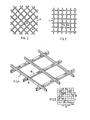
- the piece 1 of Figure 2 was a heat-set, orientated biplanar diamond mesh structure of GB 836 555.
- the piece 1 of Figure 3 was a heat-set biplanar biaxially-orientated square mesh structure of GB 1 250 478.
- Figures 2 and 3 illustrate that the pieces can be "on the diamond” or "on the square”.
- the piece 1 of Figure 4 was a deep strand structure as disclosed in GB 1 210 354. In each of Figures 2 to 4, there are intersections or junctions 5 interconnected by highly orientated strands 6: in Figures 2 and 3, the intersections 5 are unorientated whereas in Figure 4, some orientation has occurred in the intersections 5.
- the forces were applied in four or six different directions A to D or A to F, two being along the respective strands and two being along the respective diagonals. These directions were chosen because the maximum strength and the minimum strength should be represented, at least approximately. Tables 1 and 2 give the strengths at peak load together with some details of the material. In no case did the junction or intersection break. In each case, the minimum force at break was greater than 50% of the maximum.
- the extension at peak load for A and B is given in Table 2 as a percentage (as.an average for mesh structures 1 to 3). The thinnest part of any strand was roughly at its mid-point.
- Table 2 also gives the distortion load and the modified distortion load as a ratio to the weight per unit metre of the mesh structure. As the meshes were square and the structures balanced, the ratios for loads on respective diagonals were very close to each other - Table 1 gives the average. In all cases, the mesh structures had high primary dimensional stability. In all cases, the materials passed said practical flexural recovery test (mesh structure 4 is illustrated in Figure 1c).
- Mesh structures 7 and 8 were not available and were not tested, their unit weights being estimated. It is believed that they would comply with the dimensional stability and flexural recovery tests.
- Figure 6a illustrates the variation of the average (top and bottom) CBR value of a Mid-Ross Sand with 9.3% w/w moisture content (believed slightly above optimum), as the content of the mesh pieces (x) is altered (the content is given as % w/w of dry sand).
- Figure 6b shows how the dry density of the mixture (y) in tonnes per m 3 alters with the w/w content of the mesh pieces (x); the density initially rises because the pieces occupy some of the void space.
- the mesh pieces were 40 x 40 mm squares of mesh structure 4, above (as in Example 4 of Tables 4 and 5, below). The mixture was compacted in accordance with BS 5930-1981, and the bearing strength was measured in accordance with the CBR standard test.
- Figure 6c shows the variation of stress or load bearing capacity (in KN/m 2 ) against strain s (expressed as movement in mm) when Mid-Ross Sand with 9.3% moisture content, placed 170 mm deep in a 500 mm long x 75 mm wide x 500 mm deep tank is compressed by a square section 75 x 75 mm plate moving vertically downwards.
- Curve W is for sand alone; curves X, Y and Z are as for curve W but with the top 37.5, 75 mm and 150 mm respectively replaced by sand mixed with 0.1% w/w mesh pieces as for Figures 6a and 6b.
- the graph also shows in dashed lines the reversion as the plate is unloaded from the point of maximum load bearing capacity.
- W sand alone
- Z strengthened sand
- Tables 4 and 5 below give the data for the optimum CBR values, using mesh structures 4 to 6 to strengthen a Mid-Ross Sand with 9.3% w/w moisture content.
- Phough Table 4 refers to square-shaped pieces, they could be elongate. Specifically, as an example for strengthening soil, the pieces of Examples 1 to 4 could have a length of 400 mm and a width of 40 mm.
- a mass of soil (which could be from 5 m 3 up to 5 x 10 8 m 3 ) is strengthened.
- the soil was Mid-Ross Sand having a D85 value of 1.7mm and a dry density of 20 00 Kg/m 3 (moisture content was 9.3% w/w).
- Example 6 is as for Example 5, but a lower proportion of mesh pieces is used.
- Examples 7 to 9 use a lighter mesh structure (in this case the mesh structure 6 had a unit weight of 15.0).
- a 1000 x 500 x 50 mm concrete slab was formed by mixing in a conventional mixer a graded aggregate with a maximum size of 10 mm, sand, Portland cement and the pieces of Example 8 in the proportions (dry weight) 1250:370:240:6.7 (the pieces were 0.3% of the total dry weight); 180 parts water were also added.
- the slab would still be in a usable slate even if it contained a large number of cracks because of a large number of mesh pieces bridge the cracks. It would be possible to use smaller mesh pieces.
- the mesh structure 8 was heat-set, heat-setting is unnecessary for use in cement.
- the presence of particles in the aggregate which are large relative say to sand enable a normal mesh structure to be used: however, it would be possible to use a deep strand structure as in Figure 4.
- FIGS 7 and 8 show two similar machines, and the same references are used for the same or like parts.
- Each machine is in the form of a vehicle or trailer.
- Each machine has running wheels 11 and a compaction roller 12.
- Each machine has a support 13 for an e.g. one metre diameter roll 14 of mesh structure which can be for instance two metres wide.
- the mesh structure is hauled off by haul-off rolls 15, is divided into strips (say up to fifty strips) by longitudinal slitting knives 16 and is divided into pieces 1 by a rotary cutter 18 which co-operates with a ledger bar 19 below inclined guides 20: as an alternative, the roll 14 could be pre-slit into ribbon-like long narrow strips, as shown in Figure 9, each strip having at least two complete mesh openings across its width.
- the pieces 1 are guided down by a funnel 21. As the pieces 1 could stick in the funnel 21, a blower (not shown) may be incorporated to blow the pieces 1 down the funnel 21.
- a rotary multiple tine tool 22 for placing or pushing the pieces 1 in or into the ground.
- the individual tines are of different lengths and can have for instance a tip cross-section of 15 x 15 to 35 x 35 mm, being smooth truncated cones. There can be about five thousand tines on the tool 22.
- the means for placing the pieces 1 in the ground is in the form of a rotary tool 23 for digging up the top layer of soil.
- a shroud 24 which guides the thrown up soil to the bottom of the funnel 21, where the loose soil is mixed with the pieces 1.
- Both machines can be provided with side curtains 25 to reduce the possibility of wind disturbance of the pieces 1.
- the machines are towed (or pushed) in the direction of the arrow. Once the pieces 1 have been placed in the ground, the ground is compacted by the roller 12.
Priority Applications (1)
| Application Number | Priority Date | Filing Date | Title |
|---|---|---|---|
| AT83305982T ATE34195T1 (de) | 1982-10-05 | 1983-10-03 | Verstaerkung einer masse. |
Applications Claiming Priority (8)
| Application Number | Priority Date | Filing Date | Title |
|---|---|---|---|
| GB8228334 | 1982-10-05 | ||
| GB8228334 | 1982-10-05 | ||
| GB8308915 | 1983-03-31 | ||
| GB8308915 | 1983-03-31 | ||
| GB8315289 | 1983-06-03 | ||
| GB838315289A GB8315289D0 (en) | 1983-06-03 | 1983-06-03 | Strengthening matrix |
| GB838317491A GB8317491D0 (en) | 1983-06-28 | 1983-06-28 | Strengthening matrix |
| GB8317491 | 1983-06-28 |
Publications (2)
| Publication Number | Publication Date |
|---|---|
| EP0122995A1 true EP0122995A1 (fr) | 1984-10-31 |
| EP0122995B1 EP0122995B1 (fr) | 1988-05-11 |
Family
ID=27449392
Family Applications (1)
| Application Number | Title | Priority Date | Filing Date |
|---|---|---|---|
| EP83305982A Expired EP0122995B1 (fr) | 1982-10-05 | 1983-10-03 | Renforcement d'une masse |
Country Status (19)
| Country | Link |
|---|---|
| EP (1) | EP0122995B1 (fr) |
| JP (1) | JPH0694647B2 (fr) |
| KR (1) | KR920004621B1 (fr) |
| AU (1) | AU563959B2 (fr) |
| BR (1) | BR8305478A (fr) |
| CA (1) | CA1217617A (fr) |
| DE (1) | DE3376575D1 (fr) |
| DK (1) | DK158048C (fr) |
| ES (1) | ES526220A0 (fr) |
| FI (1) | FI74772C (fr) |
| GB (2) | GB2120475B (fr) |
| GR (1) | GR79699B (fr) |
| HK (1) | HK52084A (fr) |
| IE (1) | IE54595B1 (fr) |
| IN (1) | IN161172B (fr) |
| MX (1) | MX157419A (fr) |
| MY (1) | MY8500533A (fr) |
| NO (1) | NO165305C (fr) |
| SG (1) | SG19084G (fr) |
Cited By (7)
| Publication number | Priority date | Publication date | Assignee | Title |
|---|---|---|---|---|
| FR2579644A1 (fr) * | 1985-03-27 | 1986-10-03 | Rhone Poulenc Fibres | Procede pour la stabilisation des sols au moyen de filaments continus synthetiques |
| EP0285622A1 (fr) * | 1986-10-03 | 1988-10-12 | W Wayne Freed | Sol en terre renforce et procede s'y rapportant. |
| GB2275647A (en) * | 1993-02-05 | 1994-09-07 | Edward Bryan Small | Manufacture of pre-cast concrete building panels |
| NL9300602A (nl) * | 1993-04-06 | 1994-11-01 | Desmepol Bv | Bodembedekking alsmede toepassing van snippers van vliezen. |
| WO1996005374A1 (fr) * | 1994-08-13 | 1996-02-22 | Fibresand Limited | Surfaces perfectionnees destinees a la pratique de sports et d'autres activites |
| FR2727703A1 (fr) * | 1994-12-02 | 1996-06-07 | Orgel | Procede et dispositif de renforcement des sols par des additifs fibreux |
| US6042305A (en) * | 1997-08-15 | 2000-03-28 | Ppg Industries Ohio, Inc. | Fiber-reinforced soil mixtures |
Families Citing this family (11)
| Publication number | Priority date | Publication date | Assignee | Title |
|---|---|---|---|---|
| DE3444921A1 (de) * | 1984-02-24 | 1985-09-05 | VE Wohnungsbaukombinat "Wilhelm Pieck" Karl-Marx-Stadt, DDR 9044 Karl-Marx-Stadt | Textiles verbundmaterial fuer bewehrungen und verfahren zu dessen herstellung |
| AU1401388A (en) * | 1987-03-30 | 1988-09-29 | Netlon Limited | Reinforcing a grassed surface |
| GB8825781D0 (en) * | 1988-11-03 | 1988-12-07 | Netlon Ltd | Depositing reinforced matrix |
| GB8825773D0 (en) * | 1988-11-03 | 1988-12-07 | Netlon Ltd | Packing small mesh pieces |
| DE9214815U1 (fr) * | 1992-10-31 | 1993-03-25 | Basf Magnetics Gmbh, 6800 Mannheim, De | |
| FI91984C (fi) * | 1992-12-10 | 1994-09-12 | Yit Yhtymae Oy | Menetelmä maahan muodostettavan rakenteen vahvistamiseksi |
| AU4099896A (en) * | 1995-01-19 | 1996-07-25 | Orgel | Method and device for reinforcing the ground using fibrous additives |
| IT1276547B1 (it) * | 1995-04-26 | 1997-11-03 | Piccini Spa | Macchina per la frantumazione e la compattazione, in particolare per il trattamento di discariche urbane ed industriali. |
| CN104929099A (zh) * | 2014-03-18 | 2015-09-23 | 王自治 | 治沙联合作业机 |
| AU2018265763A1 (en) * | 2017-05-12 | 2019-09-19 | Csr Building Products Limited | Panel having curved reinforcement |
| CN109555245B (zh) * | 2017-09-25 | 2021-04-16 | 罗晓晖 | 幕皮式建筑 |
Citations (9)
| Publication number | Priority date | Publication date | Assignee | Title |
|---|---|---|---|---|
| GB1210354A (en) * | 1966-11-07 | 1970-10-28 | Netlon Pta Ltd | Improvements in or relating to extruded plastic net |
| DE1784576A1 (de) * | 1968-08-21 | 1971-08-12 | Ver Stahlwollefabriken Bullmer | Verfahren zum Herstellen eines Strassenbelages |
| DE2434597A1 (de) * | 1974-07-18 | 1976-01-29 | Chubb & Sons Lock & Safe Co | Sicherheitsraum wie bunker oder tresorraum und verfahren zur herstellung derartiger raeume |
| CH592219A5 (en) * | 1974-10-03 | 1977-10-14 | Arnheiter Ag Forta Seilwerke | Mesh reinforcement for concrete, tar or bitumen - is initially close-packed and expands in the mixer |
| FR2355787A1 (fr) * | 1976-02-02 | 1978-01-20 | Solvay | Compositions de mortier hydraulique et procede pour leur application |
| EP0002267A1 (fr) * | 1977-12-02 | 1979-06-13 | Hermann Schemel | Procédé pour la fabrication d'éléments en béton renforcés par des fibres, et éléments obtenus selon ledit procédé |
| FR2451902A1 (fr) * | 1979-03-23 | 1980-10-17 | France Etat | Materiau de construction comprenant un element continu souple et son application notamment pour remblai, revetement ou massif de fondation sur un sol meuble |
| GB2073090A (en) * | 1978-10-16 | 1981-10-14 | Plg Res | Plastics Material Mesh Structure |
| DE3023002A1 (de) * | 1980-06-20 | 1982-01-14 | Maschinenfabrik Klaus-Gerd Hoes, 2906 Wardenburg | Bodenstabilisierungsgeraet |
-
1980
- 1980-08-26 GB GB04260880A patent/GB2120475B/en not_active Expired
-
1983
- 1983-09-30 CA CA000438076A patent/CA1217617A/fr not_active Expired
- 1983-10-03 GB GB838326444A patent/GB8326444D0/en active Pending
- 1983-10-03 GR GR72606A patent/GR79699B/el unknown
- 1983-10-03 FI FI833593A patent/FI74772C/fi not_active IP Right Cessation
- 1983-10-03 EP EP83305982A patent/EP0122995B1/fr not_active Expired
- 1983-10-03 NO NO833593A patent/NO165305C/no unknown
- 1983-10-03 DE DE8383305982T patent/DE3376575D1/de not_active Expired
- 1983-10-04 IE IE2338/83A patent/IE54595B1/en not_active IP Right Cessation
- 1983-10-04 MX MX199000A patent/MX157419A/es unknown
- 1983-10-04 ES ES526220A patent/ES526220A0/es active Granted
- 1983-10-04 AU AU19876/83A patent/AU563959B2/en not_active Expired
- 1983-10-04 BR BR8305478A patent/BR8305478A/pt not_active IP Right Cessation
- 1983-10-04 DK DK456783A patent/DK158048C/da not_active IP Right Cessation
- 1983-10-05 KR KR1019830004720A patent/KR920004621B1/ko active IP Right Grant
- 1983-10-05 JP JP58185222A patent/JPH0694647B2/ja not_active Expired - Lifetime
- 1983-11-23 IN IN1446/CAL/83A patent/IN161172B/en unknown
-
1984
- 1984-02-29 SG SG190/84A patent/SG19084G/en unknown
- 1984-06-22 HK HK520/84A patent/HK52084A/xx not_active IP Right Cessation
-
1985
- 1985-12-30 MY MY533/85A patent/MY8500533A/xx unknown
Patent Citations (9)
| Publication number | Priority date | Publication date | Assignee | Title |
|---|---|---|---|---|
| GB1210354A (en) * | 1966-11-07 | 1970-10-28 | Netlon Pta Ltd | Improvements in or relating to extruded plastic net |
| DE1784576A1 (de) * | 1968-08-21 | 1971-08-12 | Ver Stahlwollefabriken Bullmer | Verfahren zum Herstellen eines Strassenbelages |
| DE2434597A1 (de) * | 1974-07-18 | 1976-01-29 | Chubb & Sons Lock & Safe Co | Sicherheitsraum wie bunker oder tresorraum und verfahren zur herstellung derartiger raeume |
| CH592219A5 (en) * | 1974-10-03 | 1977-10-14 | Arnheiter Ag Forta Seilwerke | Mesh reinforcement for concrete, tar or bitumen - is initially close-packed and expands in the mixer |
| FR2355787A1 (fr) * | 1976-02-02 | 1978-01-20 | Solvay | Compositions de mortier hydraulique et procede pour leur application |
| EP0002267A1 (fr) * | 1977-12-02 | 1979-06-13 | Hermann Schemel | Procédé pour la fabrication d'éléments en béton renforcés par des fibres, et éléments obtenus selon ledit procédé |
| GB2073090A (en) * | 1978-10-16 | 1981-10-14 | Plg Res | Plastics Material Mesh Structure |
| FR2451902A1 (fr) * | 1979-03-23 | 1980-10-17 | France Etat | Materiau de construction comprenant un element continu souple et son application notamment pour remblai, revetement ou massif de fondation sur un sol meuble |
| DE3023002A1 (de) * | 1980-06-20 | 1982-01-14 | Maschinenfabrik Klaus-Gerd Hoes, 2906 Wardenburg | Bodenstabilisierungsgeraet |
Non-Patent Citations (1)
| Title |
|---|
| PLASTICONSTRUCTION, vol. 5, no. 4, July/August 1975, page 165, Carl Hanser Verlag, München, DE. * |
Cited By (10)
| Publication number | Priority date | Publication date | Assignee | Title |
|---|---|---|---|---|
| FR2579644A1 (fr) * | 1985-03-27 | 1986-10-03 | Rhone Poulenc Fibres | Procede pour la stabilisation des sols au moyen de filaments continus synthetiques |
| EP0285622A1 (fr) * | 1986-10-03 | 1988-10-12 | W Wayne Freed | Sol en terre renforce et procede s'y rapportant. |
| EP0285622A4 (fr) * | 1986-10-03 | 1989-02-21 | W Wayne Freed | Sol en terre renforce et procede s'y rapportant. |
| GB2275647A (en) * | 1993-02-05 | 1994-09-07 | Edward Bryan Small | Manufacture of pre-cast concrete building panels |
| NL9300602A (nl) * | 1993-04-06 | 1994-11-01 | Desmepol Bv | Bodembedekking alsmede toepassing van snippers van vliezen. |
| WO1996005374A1 (fr) * | 1994-08-13 | 1996-02-22 | Fibresand Limited | Surfaces perfectionnees destinees a la pratique de sports et d'autres activites |
| FR2727703A1 (fr) * | 1994-12-02 | 1996-06-07 | Orgel | Procede et dispositif de renforcement des sols par des additifs fibreux |
| EP0716187A1 (fr) * | 1994-12-02 | 1996-06-12 | Orgel | Procédé et dispositif de renforcement des sols par des additifs fibreux |
| AU698936B2 (en) * | 1994-12-02 | 1998-11-12 | Orgel | Method and device for reinforcing the ground using fibrous additives |
| US6042305A (en) * | 1997-08-15 | 2000-03-28 | Ppg Industries Ohio, Inc. | Fiber-reinforced soil mixtures |
Also Published As
| Publication number | Publication date |
|---|---|
| DE3376575D1 (en) | 1988-06-16 |
| IE54595B1 (en) | 1989-12-06 |
| KR920004621B1 (ko) | 1992-06-12 |
| DK158048B (da) | 1990-03-19 |
| FI833593A (fi) | 1984-04-06 |
| DK158048C (da) | 1990-08-20 |
| FI74772C (fi) | 1988-03-10 |
| JPH0694647B2 (ja) | 1994-11-24 |
| NO833593L (no) | 1984-04-06 |
| IN161172B (fr) | 1987-10-10 |
| ES8502195A1 (es) | 1985-01-01 |
| AU563959B2 (en) | 1987-07-30 |
| FI833593A0 (fi) | 1983-10-03 |
| AU1987683A (en) | 1984-04-12 |
| SG19084G (en) | 1985-02-15 |
| GR79699B (fr) | 1984-10-31 |
| EP0122995B1 (fr) | 1988-05-11 |
| ES526220A0 (es) | 1985-01-01 |
| NO165305B (no) | 1990-10-15 |
| BR8305478A (pt) | 1984-05-15 |
| NO165305C (no) | 1991-01-23 |
| MX157419A (es) | 1988-11-22 |
| HK52084A (en) | 1984-06-22 |
| GB8326444D0 (en) | 1983-11-02 |
| FI74772B (fi) | 1987-11-30 |
| DK456783D0 (da) | 1983-10-04 |
| KR840006385A (ko) | 1984-11-29 |
| JPS59130909A (ja) | 1984-07-27 |
| MY8500533A (en) | 1985-12-31 |
| DK456783A (da) | 1984-04-09 |
| GB2120475B (en) | 1983-12-29 |
| GB2120475A (en) | 1983-12-29 |
| IE832338L (en) | 1984-04-05 |
| CA1217617A (fr) | 1987-02-10 |
Similar Documents
| Publication | Publication Date | Title |
|---|---|---|
| US4662946A (en) | Strengthening a matrix | |
| EP0122995B1 (fr) | Renforcement d'une masse | |
| US3591395A (en) | Hydraulic cementitious compositions reinforced with fibrillated plastic film | |
| JP2577235B2 (ja) | 補強土壌及び土壌補強方法 | |
| Adam et al. | Compressed stabilised earth block manufacture in Sudan | |
| US6279858B1 (en) | Woven wire netting for protection against rock falls or for securing a top layer of soil, and method and device for producing same | |
| US4940364A (en) | Concrete construction units and multi-ply concrete composites made therefrom | |
| EP0135374A2 (fr) | Structure en ciment renforcée par du tissu | |
| Kim et al. | Mode I reflection cracking resistance of strengthened asphalt concretes | |
| CN101428982A (zh) | 纤维增强材料,由其制造的产品,和制造它们的方法 | |
| EP0505010B1 (fr) | Procédé de renforcement d'une couche de revêtement de sol | |
| CN105507102B (zh) | 一种用废旧塑料编织袋加固路基的施工方法 | |
| US4903450A (en) | Concrete footer block and foundation system formed therefrom | |
| CN212533589U (zh) | 一种抗裂路基路面结构 | |
| Urquhart et al. | Design of concrete structures | |
| Kandolkar et al. | Behaviour of reinforced stone dust model walls under uniformly distributed loading | |
| CN210657841U (zh) | 一种刚柔性无缝路面基层结构 | |
| Rajeshkumar et al. | Experimental studies on viability of using geosynthetics as fibers in concrete | |
| Poernomo et al. | The Limestone as a Materials Combination of Base Course on the Road Pavement | |
| Knapton | Single pour industrial floor slabs: Specification, design, construction and behaviour | |
| RU2652411C1 (ru) | Георешетка для армирования дорожной одежды | |
| Vanelstraete et al. | Crack prevention and use of overlay systems | |
| CN216809412U (zh) | 一种用于高寒地区路基的多层格栅加固结构体 | |
| US2323435A (en) | Method of preserving quicklime | |
| CA1210942A (fr) | Armature de matrice |
Legal Events
| Date | Code | Title | Description |
|---|---|---|---|
| PUAI | Public reference made under article 153(3) epc to a published international application that has entered the european phase |
Free format text: ORIGINAL CODE: 0009012 |
|
| AK | Designated contracting states |
Designated state(s): AT BE CH DE FR IT LI LU NL SE |
|
| 17P | Request for examination filed |
Effective date: 19850206 |
|
| 17Q | First examination report despatched |
Effective date: 19860417 |
|
| GRAA | (expected) grant |
Free format text: ORIGINAL CODE: 0009210 |
|
| ITF | It: translation for a ep patent filed |
Owner name: STUDIO ING. ALFREDO RAIMONDI |
|
| AK | Designated contracting states |
Kind code of ref document: B1 Designated state(s): AT BE CH DE FR IT LI LU NL SE |
|
| PG25 | Lapsed in a contracting state [announced via postgrant information from national office to epo] |
Ref country code: AT Effective date: 19880511 |
|
| REF | Corresponds to: |
Ref document number: 34195 Country of ref document: AT Date of ref document: 19880515 Kind code of ref document: T |
|
| PG25 | Lapsed in a contracting state [announced via postgrant information from national office to epo] |
Ref country code: SE Effective date: 19880531 |
|
| REF | Corresponds to: |
Ref document number: 3376575 Country of ref document: DE Date of ref document: 19880616 |
|
| ET | Fr: translation filed | ||
| PG25 | Lapsed in a contracting state [announced via postgrant information from national office to epo] |
Ref country code: LU Free format text: LAPSE BECAUSE OF NON-PAYMENT OF DUE FEES Effective date: 19881031 |
|
| PLBE | No opposition filed within time limit |
Free format text: ORIGINAL CODE: 0009261 |
|
| STAA | Information on the status of an ep patent application or granted ep patent |
Free format text: STATUS: NO OPPOSITION FILED WITHIN TIME LIMIT |
|
| 26N | No opposition filed | ||
| ITTA | It: last paid annual fee | ||
| PGFP | Annual fee paid to national office [announced via postgrant information from national office to epo] |
Ref country code: CH Payment date: 19921012 Year of fee payment: 10 |
|
| PGFP | Annual fee paid to national office [announced via postgrant information from national office to epo] |
Ref country code: BE Payment date: 19921028 Year of fee payment: 10 |
|
| PGFP | Annual fee paid to national office [announced via postgrant information from national office to epo] |
Ref country code: NL Payment date: 19921031 Year of fee payment: 10 |
|
| PG25 | Lapsed in a contracting state [announced via postgrant information from national office to epo] |
Ref country code: LI Effective date: 19931031 Ref country code: CH Effective date: 19931031 Ref country code: BE Effective date: 19931031 |
|
| BERE | Be: lapsed |
Owner name: MERCER FRANK BRIAN Effective date: 19931031 |
|
| PG25 | Lapsed in a contracting state [announced via postgrant information from national office to epo] |
Ref country code: NL Effective date: 19940501 |
|
| NLV4 | Nl: lapsed or anulled due to non-payment of the annual fee | ||
| REG | Reference to a national code |
Ref country code: CH Ref legal event code: PL |
|
| REG | Reference to a national code |
Ref country code: FR Ref legal event code: TP |
|
| PGFP | Annual fee paid to national office [announced via postgrant information from national office to epo] |
Ref country code: DE Payment date: 19981012 Year of fee payment: 16 |
|
| PG25 | Lapsed in a contracting state [announced via postgrant information from national office to epo] |
Ref country code: DE Free format text: LAPSE BECAUSE OF NON-PAYMENT OF DUE FEES Effective date: 20000801 |
|
| PGFP | Annual fee paid to national office [announced via postgrant information from national office to epo] |
Ref country code: FR Payment date: 20021008 Year of fee payment: 20 |